EP0310533B1 - Electric locking device for fittings like espagnolette bolts or bolt locks - Google Patents
Electric locking device for fittings like espagnolette bolts or bolt locks Download PDFInfo
- Publication number
- EP0310533B1 EP0310533B1 EP19880440079 EP88440079A EP0310533B1 EP 0310533 B1 EP0310533 B1 EP 0310533B1 EP 19880440079 EP19880440079 EP 19880440079 EP 88440079 A EP88440079 A EP 88440079A EP 0310533 B1 EP0310533 B1 EP 0310533B1
- Authority
- EP
- European Patent Office
- Prior art keywords
- slide
- operating
- casing
- locking
- cover
- Prior art date
- Legal status (The legal status is an assumption and is not a legal conclusion. Google has not performed a legal analysis and makes no representation as to the accuracy of the status listed.)
- Expired - Lifetime
Links
Images
Classifications
-
- E—FIXED CONSTRUCTIONS
- E05—LOCKS; KEYS; WINDOW OR DOOR FITTINGS; SAFES
- E05C—BOLTS OR FASTENING DEVICES FOR WINGS, SPECIALLY FOR DOORS OR WINDOWS
- E05C9/00—Arrangements of simultaneously actuated bolts or other securing devices at well-separated positions on the same wing
- E05C9/02—Arrangements of simultaneously actuated bolts or other securing devices at well-separated positions on the same wing with one sliding bar for fastening when moved in one direction and unfastening when moved in opposite direction; with two sliding bars moved in the same direction when fastening or unfastening
-
- E—FIXED CONSTRUCTIONS
- E05—LOCKS; KEYS; WINDOW OR DOOR FITTINGS; SAFES
- E05C—BOLTS OR FASTENING DEVICES FOR WINGS, SPECIALLY FOR DOORS OR WINDOWS
- E05C9/00—Arrangements of simultaneously actuated bolts or other securing devices at well-separated positions on the same wing
-
- E—FIXED CONSTRUCTIONS
- E05—LOCKS; KEYS; WINDOW OR DOOR FITTINGS; SAFES
- E05B—LOCKS; ACCESSORIES THEREFOR; HANDCUFFS
- E05B47/00—Operating or controlling locks or other fastening devices by electric or magnetic means
- E05B47/0001—Operating or controlling locks or other fastening devices by electric or magnetic means with electric actuators; Constructional features thereof
- E05B2047/0014—Constructional features of actuators or power transmissions therefor
- E05B2047/0018—Details of actuator transmissions
- E05B2047/002—Geared transmissions
-
- E—FIXED CONSTRUCTIONS
- E05—LOCKS; KEYS; WINDOW OR DOOR FITTINGS; SAFES
- E05B—LOCKS; ACCESSORIES THEREFOR; HANDCUFFS
- E05B47/00—Operating or controlling locks or other fastening devices by electric or magnetic means
- E05B47/0001—Operating or controlling locks or other fastening devices by electric or magnetic means with electric actuators; Constructional features thereof
- E05B2047/0014—Constructional features of actuators or power transmissions therefor
- E05B2047/0018—Details of actuator transmissions
- E05B2047/0024—Cams
-
- E—FIXED CONSTRUCTIONS
- E05—LOCKS; KEYS; WINDOW OR DOOR FITTINGS; SAFES
- E05B—LOCKS; ACCESSORIES THEREFOR; HANDCUFFS
- E05B47/00—Operating or controlling locks or other fastening devices by electric or magnetic means
- E05B47/0001—Operating or controlling locks or other fastening devices by electric or magnetic means with electric actuators; Constructional features thereof
- E05B2047/0014—Constructional features of actuators or power transmissions therefor
- E05B2047/0018—Details of actuator transmissions
- E05B2047/0026—Clutches, couplings or braking arrangements
-
- E—FIXED CONSTRUCTIONS
- E05—LOCKS; KEYS; WINDOW OR DOOR FITTINGS; SAFES
- E05B—LOCKS; ACCESSORIES THEREFOR; HANDCUFFS
- E05B47/00—Operating or controlling locks or other fastening devices by electric or magnetic means
- E05B47/0001—Operating or controlling locks or other fastening devices by electric or magnetic means with electric actuators; Constructional features thereof
- E05B47/0012—Operating or controlling locks or other fastening devices by electric or magnetic means with electric actuators; Constructional features thereof with rotary electromotors
-
- Y—GENERAL TAGGING OF NEW TECHNOLOGICAL DEVELOPMENTS; GENERAL TAGGING OF CROSS-SECTIONAL TECHNOLOGIES SPANNING OVER SEVERAL SECTIONS OF THE IPC; TECHNICAL SUBJECTS COVERED BY FORMER USPC CROSS-REFERENCE ART COLLECTIONS [XRACs] AND DIGESTS
- Y10—TECHNICAL SUBJECTS COVERED BY FORMER USPC
- Y10T—TECHNICAL SUBJECTS COVERED BY FORMER US CLASSIFICATION
- Y10T292/00—Closure fasteners
- Y10T292/08—Bolts
- Y10T292/096—Sliding
- Y10T292/1014—Operating means
- Y10T292/1021—Motor
-
- Y—GENERAL TAGGING OF NEW TECHNOLOGICAL DEVELOPMENTS; GENERAL TAGGING OF CROSS-SECTIONAL TECHNOLOGIES SPANNING OVER SEVERAL SECTIONS OF THE IPC; TECHNICAL SUBJECTS COVERED BY FORMER USPC CROSS-REFERENCE ART COLLECTIONS [XRACs] AND DIGESTS
- Y10—TECHNICAL SUBJECTS COVERED BY FORMER USPC
- Y10T—TECHNICAL SUBJECTS COVERED BY FORMER US CLASSIFICATION
- Y10T292/00—Closure fasteners
- Y10T292/57—Operators with knobs or handles
-
- Y—GENERAL TAGGING OF NEW TECHNOLOGICAL DEVELOPMENTS; GENERAL TAGGING OF CROSS-SECTIONAL TECHNOLOGIES SPANNING OVER SEVERAL SECTIONS OF THE IPC; TECHNICAL SUBJECTS COVERED BY FORMER USPC CROSS-REFERENCE ART COLLECTIONS [XRACs] AND DIGESTS
- Y10—TECHNICAL SUBJECTS COVERED BY FORMER USPC
- Y10T—TECHNICAL SUBJECTS COVERED BY FORMER US CLASSIFICATION
- Y10T292/00—Closure fasteners
- Y10T292/62—Bolt casings
Definitions
- the invention relates to a fitting for a door, window or the like, comprising, on the one hand, a cremone bolt or cremone bolt provided with a housing in which is housed a control mechanism making it possible to actuate at least one operating rod and , on the other hand, an electric locking device provided with motor means for driving blocking means moving perpendicularly relative to the operating rod or rods, this, in the terms of the preamble of claim 1.
- the present invention will find its application, more particularly, in the field of building hardware.
- the bolts or bolts-locks for door, window or the like consist of a housing secured to a headrest and in which is housed a control mechanism allowing the user to actuate one or more locking elements.
- the latter consist of one or two operating rods extending on either side of the housing and sliding behind the headrest of the cremone bolt or cremone bolt.
- These rods are provided with one or a plurality of locking members, for example bits or rollers, emerging from said headrest through slots machined therein, so as to cooperate with strikes integral with the sleeping frame of the door, window or the like.
- cremone bolts In the context of cremone bolts, these are provided with a key element making it possible to immobilize in translation the rod or rods or to annihilate the action of the user on an operating member, such as a crutch, button or other.
- an operating member such as a crutch, button or other.
- the control mechanism of these bolts and bolts also makes it possible to actuate another locking element and, in particular, a latch bolt.
- cremones or cremone bolts have been designed provided with an electrical locking device comprising motor means making it possible to actuate directly or by means of a secondary connection part, one or more locking elements.
- motor means consisting of either an electric motor or an electromagnet, can control the movement of a latch bolt and / or one or more rods.
- the cremone bolt or bolt lock containing said motor means, has dimensions greater than a standard casing and requires a deeper and wider notching in the edge of the opening to allow its embedding.
- specific notching requires the use of a tool different from that usually used. Note also, that the amount of the opening must have a sufficient thickness allowing the notching
- motor means operating on the blocking system are known, for example the key element, for immobilizing the locking elements.
- Such drive means require less power to impart translation or rotation to a blocking element when locking or locking the opening of a door, window or the like.
- the electrical locking device and, in particular, the drive means are located on the door leaf and act on the control mechanism embedded in the edge of the this last. This solution only partially solves the problem since it requires the machining of the internal face of said opening.
- this auxiliary locking device consists of an electromagnet provided with a locking pin capable of cooperating with a control member actuating one or more of the locking elements of the lever or lever-lock.
- This control member can be an easel acting on a tilting bolt integrated in the front edge of the door or window.
- this auxiliary locking device can also be associated with the main housing containing the control mechanism of said cremone bolt or cremone bolt.
- the electromagnet imposes a notching of increased depth of the edge before the opening welcoming the lever or lever-lock.
- the present invention proposes, precisely, to limit the importance of this notching.
- the object of the present invention is to remedy all of the aforementioned drawbacks.
- the invention as characterized in the claims solves the problem of creating a fitting for door, window or the like comprising, on the one hand, a cremone bolt or cremone bolt provided with a housing integral with a headrest and in which is housed a control mechanism making it possible to actuate at least one operating rod, and, on the other hand, an electrical locking device which is, on the one hand, in the form of a separate assembly from the cremone bolt or cremone bolt, and placed, either at any place located in the longitudinal extension and on either side of the housing, or in the immediate extension of the latter, in an adjoining manner at one of the ends thereof, and secondly, having blocking means, subject to motor means and electrical control members, and cooperating with the control mechanism and / or the operating rod, said blocking means being constituted s by a slide moving perpendicular to the longitudinal axis of the operating rod, and having a front end cooperating, in the locked position, with said control mechanism and / or the operating rod, said motor means being dissociated from said blocking means
- Another advantage obtained thanks to this invention consists in that the association of the electric locking device with a cremone bolt or cremone bolt does not generate any more modifications of the constituent elements of the control mechanism and hardly any modifications of the box containing the latter. Therefore, it is advantageous to be able to adapt the electrical locking device to any lever or lever-lock already installed, with very few modifications to be made except the longitudinal enlargement of the notching.
- FIG. 6 represents a plan view of the guide element illustrated in FIG. 5.
- the fitting 1, for door, window or the like, in accordance with the invention, comprises a cremone bolt or locking bolt 81, formed essentially of a housing 2 attached to the internal face of a headrest 82 (not shown) and intended to be embedded in the edge of an opening.
- the housing 2 serves as a housing for a control mechanism 3 whose function consists in transmitting the action of a user on any control member, for example, a crutch or a key element, on one or more locking elements .
- this control mechanism 3 makes it possible to actuate at least one operating rod 83 extending on one side or the other of the housing 2.
- This operating rod 83 carries, as a general rule, a plurality of members locking, such as rollers, bits or the like, which are able to cooperate with strikes arranged on the frame.
- control mechanism 3 also makes it possible to actuate another locking element and, in particular, a latch bolt 4.
- the fitting 1 comprises an electrical locking device 6, controlled remotely and the function consists in immobilizing, in the locked position and after closing the opening of the door, window or the like, a mobile member of the control mechanism 3 and / or the operating rod or rods 83 of the lever or lever-bolt 81.
- this electrical locking device 6 is located in the longitudinal extension of the housing 2 and is in the form of a separate assembly consisting of a second housing 7.
- This latter contains, more precisely, electrical control members 8 actuating motor means 9 ensuring the driving of blocking means 10.
- said housing 7 is composed of a cover 11 and an enantiomorphic bottom 12 comprising a series of housings in which the aforementioned elements take place. It is important to note that the thickness 7A, as well as the width 7B, of this housing 7, does not exceed the corresponding dimensions of the housing 2 of the cremone bolt or cremone bolt. This allows the use of identical tools when notching the edge of the opening.
- this electrical locking device 6 can be embedded in the edge of an opening, either in the immediate extension and in a glued manner to the housing 2, or at any place, located on one side or on the other of the latter.
- the cover 11 and the bottom 12 of the housing 7 have, as shown in FIG. 1, a particular morphology at their part denoted 13 and cooperating with the housing 2, this characteristic having the function of ensuring their adaptation to one of the ends 2A, of the latter.
- said housing 2 is devoid, at one of its ends 2A, situated on the longitudinal axis of the operating rod or rods, of the wall forming the edge and connecting the front and rear covering plates of this housing 2.
- the part 13 of the cover 11 and of the bottom 12 constituting the housing 7 can be introduced, partially, for example, into the upper edge 14 of the housing 2, as shown in FIG. 1, and play a role of 'spacer coming to be inserted between the covering walls of the latter.
- This part 13 of the cover 11 and the bottom 12 is further provided with corresponding holes 15 with openings machined in said cover plates.
- These orifices 15 serve as passage for fixing members, such as screws, rivets or the like, to make the electrical locking device 6 secured to the casing 2 of the cremone bolt or cremone bolt.
- cover 11 and of the bottom 12 makes it possible to ensure the reversibility of the electrical locking device 6, this both for right-left use on the opening, but also with respect to a median plane transverse to the housing 2 of the cremone bolt or bolt lock 81.
- control members 8 making it possible to actuate the motor means 9 are composed of a control relay system 16 disposed in a housing 17 located in the upper part 17A of the housing 7. These members 8 electrical control also include a connection element 18 for connection with an external power supply connected, for example, to a control unit.
- connection element 18 the bottom 12 and / or the cover 11 include a light allowing the introduction of a connection plug.
- the electrical control members 8 intervene in the operation of the motor means 9 and, more particularly, of an electric motor driving the blocking means 10.
- the locking means 10, actuated by the electric motor 9, consist, essentially, of a slide 19 moving in the housing 7, perpendicular to the longitudinal axis of the operating rods.
- the front end 20 of this slide 19 is able to cooperate, in the locking position, either with one of these operating rods 83, or with a connecting element 21, connected to the control mechanism 3.
- this front end 20 of the slider 19 can immobilize either an operating rod 83 or a connecting element 21, and, simultaneously, cooperate with the headrest 82 of the lever or lever-lock.
- said headrest 82 plays the role of waste and comprises, for this purpose, an opening or a lumen in which the locking means 10 partially engage.
- this necessarily has a displacement in a direction substantially parallel to said operating rods 83, under the action of the control mechanism 3.
- Figure 1 shows a fitting whose electrical locking device 6 and, in particular, the slider 19, cooperates with such a connecting element 21.
- the latter is connected to the bridge 5 giving two operating rods, s 'extending on either side of the housing 2, an identical displacement.
- this connecting element 21 can be connected to any part of the control mechanism 3 and whose movement takes place according to the aforementioned conditions.
- the locking of the opening of a door, window or the like is obtained by moving the slide 19 in the direction of the headrest 82, so that its front end 20 is positioned at above the upper edge 22 of the connecting element 21, immobilizing the latter in its locked position.
- the withdrawal of the slider 19 frees the control mechanism 3 while ensuring a displacement parallel to the operating rods to said connecting element 21.
- the guide of the slide 19 is ensured by a set of ranges 23, 24, 25 arranged in the bottom 12 and in the cover 11 of the housing 7.
- said slide 19 is provided at its front end 20 with a shoe 26 whose upper edge 27 cooperates with a bearing 28 arranged in the bottom 12 and the cover 11, parallel to the movement of the slide 19. In the locked position, this shoe 26 is located in the extension of the connecting element 21.
- this shoe 26 is in the form of an element 70 in its own right, attached to the upper end 71 of a vertical branch 72 secured to the front end 20 of the slide 19. To this end, a cut is made in the upper edge 73 of this vertical branch 72, the lateral edges of which are able to engage in grooves 74 machined on either side of the shoe 26.
- the latter is able to place itself, in the locked position, above the connecting element 21, or even to act on an operating rod.
- This shoe 26 or, more precisely, the element 70 also cooperates, at its upper edge 75 with the bearing 28 arranged in the bottom 12 and the cover 11 and this, whatever the position of the slide 19.
- said operating rod 83 is provided with a light coming to be situated, in the locked position, in line with the slide 19.
- the front end 20 of the latter engages in this light arranged in the operating rod to immobilize the latter.
- the shoe 26, whether or not defined by a separable element 70, can advantageously constitute a locking bolt which is able to penetrate, in the locked position, into the keeper formed by the opening in the headrest 82.
- This arrangement gives perfect reliability to the electrical locking device 6 since a forced action on the control mechanism 3 does not, in any case, deteriorate it.
- shoe 26, in the form of the element 70 can be made of a more resistant material than that of the slide 19. This results in a reduction in the manufacturing cost of the latter and an increased longevity of the electrical locking device 6.
- the front end 20 of the slide 19 or the front face 76 of the shoe 26 are slightly chamfered around their outline or have a bias cut at the level of the lower part facilitating their engagement, either in a slot machined in the operating rod 83 and / or in the headrest 82, ie above the upper edge 22 of the connecting element 21.
- the electric motor 9, making it possible to drive the slide 19, is introduced into a housing 29 arranged in the cover 11 and the bottom 12 of the housing 7. More particularly, this housing 29 ensures the rotation rotation of the electric motor 9. It has , for this purpose, a substantially cylindrical shape and comprises, on its internal wall and at one of its ends, an internal rim cooperating with a peripheral groove produced in the wall of the electric motor 9. During assembly, it is important that the engagement of this internal rim in the aforementioned peripheral groove takes place with a certain resistance. Of course, other means for blocking the rotation of the electric motor 9 can be envisaged.
- the housing 29 also makes it possible to position the latter relative to the slider 19.
- said housing 29 is arranged so that the drive shaft 30 of the electric motor 9 is perpendicular to the movement of the slider 19 and is able to cooperate with the latter via appropriate drive means 31.
- the drive means 31 consist of a toothed wheel 32 mounted at the end of the drive shaft 30 and cooperating with a rack 33 machined in a slot 34 arranged in the slide 19.
- the drive of the electric motor 9 causes the rotation of the toothed wheel 32 and the translation of the slider 19 inside the housing 7.
- the slider 19 comprises stop control means 36, 37 of the operation of the electric motor 9.
- these stop control means 36, 37 are constituted by wings 38, 39, extending, respectively, on either side of and from the slide 19.
- These wings 38, 39 constitute control fingers actuating, respectively, a stop switch at blocking 40 and a stop switch at opening 41.
- the designation of these switches 40, 41 is chosen by analogy to their function.
- the blocking stop switch 40 causes the electric motor 9 to stop when the slide 19 is in the advanced blocking position.
- the opening stop switch 41 controls the stop of the operation of the electric motor 9 when said slide 19 is in the retracted position, having released the control mechanism 3 and, more particularly, the connecting element 21 or the rod. maneuver.
- one 39 of the wings 38, 39 extending on either side of the slide 19 also serves as a manual control member of the latter. Indeed, for security reasons, it seems essential to be able to control the unlocking of the rods for operating the cremone bolt or bolt lock when the electric locking device 6 is put out of use or if its control is inaccessible.
- the bottom 12 and / or the cover 11 is provided with a light 42 arranged in line with the wing 39 to ensure accessibility to the latter and to control the advance and, as a general rule, the decline of the slide 19.
- this light 42 is of semicircular shape facilitating the transmission of the external action to the housing 7 on the slide 19.
- the drive means 31 can be formed, according to a second embodiment, by an eccentric secured to a disc driven in rotation by the drive shaft 30 of the electric motor 9.
- the slider 19 comprises, as shown in FIG. 3, on the one hand, a groove 43 in which the disc cited above is housed and moves.
- the slide 19 is provided with a cutout 44 machined in one of its lateral edges 45 and extending transversely to its longitudinal axis. Therefore, during the operation of the electric motor 9, the eccentric moves inside the cutout 44 while causing the slide 19 to move back or forward.
- the drive means 31 consist, according to a third embodiment shown in FIG. 4, on the one hand, of a disc 50 secured to the drive shaft 30 and bearing an eccentric 51. The latter is engaged in a cutout 52 machined in the slide 19 and having a morphology identical to the cutout 44 described above.
- these drive means 31 comprise a manual control pusher 46 composed of a wing 47 extending parallel and above the slide 19 and a control lever 48 secured to one of the longitudinal edges 77 of said wing 47 and extending below the slide 19.
- the wing 47 of this control pusher 46 is provided with a rack 49 meshing on a ring gear 78 surmounting the disc 50. Furthermore, the control lever 48 is inserted in a recess 79 produced in the lateral edge 80 of the slide 19 and is in the same plane, perpendicular to the housing 7, as the wing 39 constituting the stop control means 37. This arrangement ensures accessibility to said control lever 48 by means of light 42.
- FIGs 5 and 6 is shown a guide member 54 attached to the end 2A of the housing 2 of the lever or lever-lock, where the electrical locking device is located 6. More precisely, this guide element 54 allows 'ensure the functions which are usually fulfilled by the edge of the case which does not exist in the context of the lever or lever-bolt shown in Figure 1.
- this guide element 54 makes it possible to maintain and guide the operating rod 83 and, moreover, the connection between the housing 2 and the headrest 82.
- it also makes it possible to guide the connecting element 21 during its movements parallel to the longitudinal axis of the operating rod or rods.
- this guide element 54 consists of a body 55 of parallelepiped shape and of width 56 substantially equal to the distance respected by the front and rear cover plates forming the housing 2.
- This body 55 is provided, on its lateral sides 57, with a tongue 58 cooperating with an opening made in said cover plates to ensure, after assembly of the latter, the connection between the guide element 54 and the housing 2.
- flanks 59 located on these same lateral sides 57 of the body 55, are projecting with respect to the front face 60 of the latter. Between these two flanks 59 are caused to move, simultaneously, an operating rod 83 and the connecting element 21.
- This front face 60 of the body 55 also has a central boss 61 which engages in the slots machined respectively in said connecting element 21 and in the operating rod 83.
- a pin 62 disposed on this central boss 61 makes it possible to position box 2 of the cremone bolt or lock-bolt on the headrest 82.
- a threaded orifice 63 placed under the central boss 61, authorizes the engagement of a screw ensuring their connection.
Abstract
Description
L'invention concerne une ferrure pour porte, fenêtre ou analogue, comprenant, d'une part, une crémone ou crémone-serrure pourvue d'un boîtier dans lequel est logé un mécanisme de commande permettant d'actionner au moins une tringle de manoeuvre et, d'autre part, un dispositif de condamnation électrique muni de moyens moteurs pour entraîner des moyens de blocage se déplaçant perpendiculairement par rapport à la ou aux tringles de manoeuvre, cela, selon les termes du préambule de la revendication 1.The invention relates to a fitting for a door, window or the like, comprising, on the one hand, a cremone bolt or cremone bolt provided with a housing in which is housed a control mechanism making it possible to actuate at least one operating rod and , on the other hand, an electric locking device provided with motor means for driving blocking means moving perpendicularly relative to the operating rod or rods, this, in the terms of the preamble of
La présente invention trouvera son application, plus particulièrement, dans le domaine de la quincaillerie du bâtiment.The present invention will find its application, more particularly, in the field of building hardware.
Habituellement, les crémones ou crémones-serrures pour porte, fenêtre ou analogue se composent d'un boîtier solidaire d'une têtière et dans lequel est logé un mécanisme de commande permettant à l'usager d'actionner un ou plusieurs éléments de verrouillage.Usually, the bolts or bolts-locks for door, window or the like consist of a housing secured to a headrest and in which is housed a control mechanism allowing the user to actuate one or more locking elements.
En règle générale, ces derniers sont constitués par une ou deux tringles de manoeuvre s'étendant de part et d'autre du boîtier et coulissant derrière la têtière de la crémone ou crémone-serrure. Ces tringles sont munies d'un ou d'une pluralité d'organes de verrouillage, par exemple des pannetons ou des rouleaux, débouchant de ladite têtière au travers de lumières usinées dans cette dernière, de manière à coopérer avec des gâches solidaires du cadre dormant de la porte, fenêtre ou analogue.As a general rule, the latter consist of one or two operating rods extending on either side of the housing and sliding behind the headrest of the cremone bolt or cremone bolt. These rods are provided with one or a plurality of locking members, for example bits or rollers, emerging from said headrest through slots machined therein, so as to cooperate with strikes integral with the sleeping frame of the door, window or the like.
Dans le cadre de crémones-serrures, celles-ci sont pourvues d'un élément à clé permettant d'immobiliser en translation la ou les tringles ou d'annihiler l'action de l'usager sur un organe de manoeuvre, tel qu'une béquille, un bouton ou autre. De plus, le mécanisme de commande de ces crémones-serrures permet également d'actionner un autre élément de verrouillage et, notamment, un pêne demi-tour.In the context of cremone bolts, these are provided with a key element making it possible to immobilize in translation the rod or rods or to annihilate the action of the user on an operating member, such as a crutch, button or other. In addition, the control mechanism of these bolts and bolts also makes it possible to actuate another locking element and, in particular, a latch bolt.
Dans certains cas, il peut s'avérer particulièrement intéressant d'assurer la commande à distance du verrouillage d'un ouvrant pourvu d'une telle crémone ou crémone-serrure.In certain cases, it may prove to be particularly advantageous to ensure the remote control of the locking of an opening leaf provided with such a lever or lever-lock.
A cet effet, on a conçu des crémones ou crémones-serrures pourvues d'un dispositif de condamnation électrique comportant des moyens moteurs permettant d'actionner directement ou par l'intermédiaire d'une pièce de liaison secondaire, un ou plusieurs éléments de verrouillage. Ainsi, ces moyens moteurs, constitués soit par un moteur électrique ou un électro-aimant, peuvent commander le déplacement d'un pêne demi-tour et/ou d'une ou des tringles.To this end, cremones or cremone bolts have been designed provided with an electrical locking device comprising motor means making it possible to actuate directly or by means of a secondary connection part, one or more locking elements. Thus, these motor means, consisting of either an electric motor or an electromagnet, can control the movement of a latch bolt and / or one or more rods.
En règle générale, ces dispositifs de condamnation électriques présentent un encombrement relativement important en raison des moyens moteurs dont la puissance doit être suffisante pour provoquer le déplacement des éléments de verrouillage. De ce fait, le boîtier de la crémone ou crémone-serrure, renfermant lesdits moyens moteurs, présente des dimensions supérieures à un boîtier standard et nécessite un entaillage plus profond et plus large dans le chant de l'ouvrant pour permettre son encastrement. Or, un tel entaillage spécifique impose l'utilisation d'un outillage différent de celui habituellement mis en oeuvre. A noter également, que le montant de l'ouvrant doit comporter une épaisseur suffisante autorisant l'entaillageIn general, these electrical locking devices have a relatively large size due to the motor means whose power must be sufficient to cause the displacement of the locking elements. Therefore, the cremone bolt or bolt lock, containing said motor means, has dimensions greater than a standard casing and requires a deeper and wider notching in the edge of the opening to allow its embedding. However, such specific notching requires the use of a tool different from that usually used. Note also, that the amount of the opening must have a sufficient thickness allowing the notching
Par ailleurs, dans le cadre de crémones-serrures, on connaît des moyens moteurs intervenant sur le système de blocage, par exemple l'élément à clé, pour immobiliser les éléments de verrouillage. De tels moyens moteurs nécessitent une puissance moindre pour conférer une translation ou une rotation à un élément de blocage lors de la condamnation ou du verrouillage de l'ouvrant d'une porte, fenêtre ou analogue.Furthermore, in the context of locks and bolts, motor means operating on the blocking system are known, for example the key element, for immobilizing the locking elements. Such drive means require less power to impart translation or rotation to a blocking element when locking or locking the opening of a door, window or the like.
Cependant, cette réduction de puissance des moyens moteurs ne permet pas de résoudre les problèmes précités. En effet, quel que soit l'encombrement d'un moteur électrique ou d'un électro-aimant, leur insertion dans le boîtier d'une crémone-serrure engendre, inévitablement, une augmentation de la taille de ce boîtier. Il en résulte un entaillage plus large et, en tous les cas, plus profond du chant de l'ouvrant.However, this reduction in power of the motor means does not make it possible to resolve the aforementioned problems. Indeed, whatever the size of an electric motor or an electromagnet, their insertion in the housing of a lock-bolt inevitably generates an increase in the size of this housing. This results in a wider cut and, in any case, deeper in the edge of the opening.
Dans certains cas, le dispositif de condamnation électrique et, notamment, les moyens moteurs sont situés en applique sur l'ouvrant et interviennent sur le mécanisme de commande encastré dans le chant de ce dernier. Cette solution ne résout que partiellement le problème étant donné qu'il nécessite l'usinage de la face interne dudit ouvrant.In certain cases, the electrical locking device and, in particular, the drive means are located on the door leaf and act on the control mechanism embedded in the edge of the this last. This solution only partially solves the problem since it requires the machining of the internal face of said opening.
Un autre inconvénient que présente, en général, l'association d'un dispositif de condamnation électrique avec une crémone ou crémone-serrure consiste en ce qu'un grand nombre des pièces du mécanisme de commande de cette dernière comporte, obligatoirement, une configuration particulière pour autoriser l'intégration des moyens moteurs.Another disadvantage that presents, in general, the association of an electrical locking device with a cremone bolt or cremone bolt consists in that a large number of the parts of the latter's control mechanism necessarily have a particular configuration to authorize the integration of the driving means.
Il est donc nécessaire de gérer une fabrication plus lourde et un stock plus important pour disposer de crémones ou crémones-serrures dont certaines sont pourvues d'un dispositif de condamnation électrique et d'autres non.It is therefore necessary to manage a heavier production and a larger stock to have cremone bolts or bolts-locks, some of which are provided with an electrical locking device and others which are not.
Il est également connu, selon le document antérieur EP-A-0173987 un dispositif de condamnation auxiliaire à commande électrique associé à une crémone ou crémone-serrure.It is also known, according to the prior document EP-A-0173987, an electrically controlled auxiliary locking device associated with a cremone bolt or cremone bolt.
En fait, ce dispositif de condamnation auxiliaire consiste en un électro-aimant muni d'un téton de blocage susceptible de coopérer avec un organe de commande actionnant l'un ou les éléments de verrouillage de la crémone ou crémone-serrure. Cet organe de commande peut être un chevalet agissant sur un pêne basculant intégré dans le chant avant de la porte ou fenêtre.In fact, this auxiliary locking device consists of an electromagnet provided with a locking pin capable of cooperating with a control member actuating one or more of the locking elements of the lever or lever-lock. This control member can be an easel acting on a tilting bolt integrated in the front edge of the door or window.
Cependant, ce dispositif de condamnation auxiliaire peut encore être associé au boîtier principal renfermant le mécanisme de commande de ladite crémone ou crémone-serrure.However, this auxiliary locking device can also be associated with the main housing containing the control mechanism of said cremone bolt or cremone bolt.
Toutefois, pour permettre à cet électro-aimant d'assurer la fonction qui lui est attribuée, il doit nécessairement, être fixé, solidement, soit au boîtier principal de la crémone ou crémone-serrure, soit sur l'un des boîtiers renfermant un élément de verrouillage. En conséquence, l'association d'un tel dispositif de condamnation auxiliaire nécessite un aménagement spécifique de la crémone ou crémone-serrure. Celle-ci s'écarte, ainsi, des caractéristiques standard et impose une gestion de fabrication et de stockage supplémentaire.However, to allow this electromagnet to perform the function assigned to it, it must necessarily be fixed securely either to the main casing of the cremone bolt or cremone bolt, or to one of the housings containing an element lock. Consequently, the combination of such an auxiliary locking device requires a specific arrangement of the cremone bolt or cremone bolt. This deviates from the standard characteristics and requires additional manufacturing and storage management.
Par ailleurs, en raison de sa disposition perpendiculaire aux tringles de manoeuvre, l'électro-aimant impose un entaillage de profondeur accrue du chant avant de l'ouvrant accueillant la crémone ou crémone-serrure. Or, la présente invention se propose, justement, de limiter l'importance de cet entaillage.Furthermore, because of its arrangement perpendicular to the operating rods, the electromagnet imposes a notching of increased depth of the edge before the opening welcoming the lever or lever-lock. However, the present invention proposes, precisely, to limit the importance of this notching.
De plus, l'action directe et unique du téton de blocage sur un organe de commande quelconque, présente certains inconvénients. Notamment, les agissements d'un aigrefin sur cet organe de commande sont répercutés, intégralement, sur ledit téton de blocage dont la résistance est relativement limitée.In addition, the direct and unique action of the locking pin on any control member has certain drawbacks. In particular, the actions of a haddock on this control member are passed on, in full, to said blocking pin whose resistance is relatively limited.
Cependant, au cas où l'ensemble résiste à ces agissements, il est probable que le téton de blocage ait subi une telle déformation qu'il met hors d'usage l'électro-aimant. Or, dans ces conditions, aucune solution n'est offerte à l'usager pour déverrouiller à nouveau la porte ou fenêtre.However, if the assembly resists these actions, it is likely that the locking pin has undergone such a deformation that it puts the electromagnet out of use. However, under these conditions, no solution is offered to the user to unlock the door or window again.
La présente invention a pour but de remédier à l'ensemble des inconvénients précités.The object of the present invention is to remedy all of the aforementioned drawbacks.
L'invention telle qu'elle est caractérisée dans les revendications résout le problème consistant à créer une ferrure pour porte, fenêtre ou analogue comprenant, d'une part, une crémone ou crémone-serrure pourvue d'un boîtier solidaire d'une têtière et dans lequel est logé un mécanisme de commande permettant d'actionner au moins une tringle de manoeuvre, et, d'autre part, un dispositif de condamnation électrique se présentant, d'une part, sous forme d'un ensemble séparé de la crémone ou crémone-serrure, et placé, soit à un endroit quelconque situé dans le prolongement longitudinal et de part et d'autre du boîtier, soit dans le prolongement immédiat de ce dernier, de manière accolée à l'une des extrémités de celui-ci, et d'autre part, présentant des moyens de blocage, assujettis à des moyens moteurs et des organes de commande électrique, et coopérant avec le mécanisme de commande et/ou la tringle de manoeuvre, lesdits moyens de blocage étant constitués par un coulisseau se déplaçant perpendiculairement à l'axe longitudinal de la tringle de manoeuvre, et présentant une extrémité avant coopérant, en position de condamnation, avec ledit mécanisme de commande et/ou la tringle de maneouvre, lesdits moyens moteurs étant dissociés desdits moyens de blocage et agissant selon un axe perpendiculaire au déplacement dudit coulisseau.The invention as characterized in the claims solves the problem of creating a fitting for door, window or the like comprising, on the one hand, a cremone bolt or cremone bolt provided with a housing integral with a headrest and in which is housed a control mechanism making it possible to actuate at least one operating rod, and, on the other hand, an electrical locking device which is, on the one hand, in the form of a separate assembly from the cremone bolt or cremone bolt, and placed, either at any place located in the longitudinal extension and on either side of the housing, or in the immediate extension of the latter, in an adjoining manner at one of the ends thereof, and secondly, having blocking means, subject to motor means and electrical control members, and cooperating with the control mechanism and / or the operating rod, said blocking means being constituted s by a slide moving perpendicular to the longitudinal axis of the operating rod, and having a front end cooperating, in the locked position, with said control mechanism and / or the operating rod, said motor means being dissociated from said blocking means and acting along an axis perpendicular to the movement of said slide.
Les avantages obtenus grâce à cette invention consistent essentiellement en ce que l'emplacement du dispositif de condamnation électrique par rapport au boîtier de la crémone ou crémone-serrure permet d'éviter un entaillage plus profond et plus large du montant de l'ouvrant. Seul un entaillage longitudinal supplémentaire est nécessaire, ce qui permet l'utilisation d'un outillage standard. A noter que cet entaillage supplémentaire peut être réalisé soit dans le prolongement immédiat de celui aménagé pour le boîtier de la crémone ou crémone-serrure, soit à un endroit quelconque sur le chant de l'ouvrant.The advantages obtained thanks to this invention consist essentially in that the location of the electrical locking device with respect to the case of the cremone bolt or cremone bolt prevents a deeper and wider notching of the amount of the opening. Only an additional longitudinal notching is necessary, which allows the use of standard tools. Note that this additional notching can be carried out either as an immediate extension of that arranged for the cremone bolt or cremone bolt, or at any location on the edge of the opening.
Un autre avantage obtenu grâce à cette invention consiste en ce que l'association du dispositif de condamnation électrique à une crémone ou crémone-serrure n'engendre plus de modifications des éléments constitutifs du mécanisme de commande et guère de modifications du boîtier renfermant ce dernier. De ce fait, il est avantageux de pouvoir adapter le dispositif de condamnation électrique à toute crémone ou crémone-serrure déjà installée, en ayant que très peu de modifications à effectuer si ce n'est l'agrandissement longitudinal de l'entaillage.Another advantage obtained thanks to this invention consists in that the association of the electric locking device with a cremone bolt or cremone bolt does not generate any more modifications of the constituent elements of the control mechanism and hardly any modifications of the box containing the latter. Therefore, it is advantageous to be able to adapt the electrical locking device to any lever or lever-lock already installed, with very few modifications to be made except the longitudinal enlargement of the notching.
L'invention est exposée ci-après plus en détail à l'aide de dessins représentant seulement un mode d'exécution.
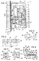
- ― la figure 1 représente un vue partielle, schématisée et en élévation d'une ferrure, conforme à l'invention, comprenant une crémone ou crémone-serrure et un dispositif de condamnation électrique (les couvercles des boîtiers dudit dispositif de condamnation électrique et de la crémone ou crémone-serrure ayant été retirés).
- ― la figure 2 représente une vue en plan du boîtier du dispositif de condamnation électrique.
- ― la figure 3 représente une vue en élévation des moyens de blocage du dispositif de condamnation électrique, selon un second mode d'exécution.
- ― la figure 4 représente une vue en élévation des moyens de blocage du dispositif de condamnation électrique selon un troisième mode d'exécution.
- ― la figure 5 représente une vue en élévation de l'élément de guidage rapporté à une extrémité du boîtier de la crémone ou crémone-serrure.
- - Figure 1 shows a partial view, schematically and in elevation of a fitting, according to the invention, comprising a lever or lever-lock and an electrical locking device (the covers of the housings of said electrical locking device and the lever or lever-bolt having been removed).
- - Figure 2 shows a plan view of the housing of the electrical locking device.
- - Figure 3 shows an elevational view of the locking means of the electrical locking device, according to a second embodiment.
- - Figure 4 shows an elevational view of the locking means of the electrical locking device according to a third embodiment.
- - Figure 5 shows an elevational view of the guide element attached to one end of the cremone bolt or bolt lock.
La figure 6 représente une vue en plan de l'élément de guidage illustré dans la figure 5.FIG. 6 represents a plan view of the guide element illustrated in FIG. 5.
On se réfère plus particulièrement aux figures 1 et 2.Reference is made more particularly to FIGS. 1 and 2.
La ferrure 1, pour porte, fenêtre ou analogue, conforme à l'invention, comporte une crémone ou crémone-serrure 81, formée, essentiellement, d'un boîtier 2 rapporté sur la face interne d'une têtière 82 (non représentée) et destiné à être encastré dans le chant d'un ouvrant.The
Le boîtier 2 sert de logement à un mécanisme de commande 3 dont la fonction consiste à transmettre l'action d'un usager sur un organe de commande quelconque, par exemple, une béquille ou un élément à clé, sur un ou plusieurs éléments de verrouillage.The housing 2 serves as a housing for a control mechanism 3 whose function consists in transmitting the action of a user on any control member, for example, a crutch or a key element, on one or more locking elements .
Ainsi, ce mécanisme de commande 3 permet d'actionner au moins une tringle de manoeuvre 83 s'étendant d'un côté ou de l'autre du boîtier 2. Cette tringle de manoeuvre 83 porte, en règle générale, une pluralité d'organes de verrouillage, tels que des rouleaux, des pannetons ou autre, qui sont en mesure de coopérer avec des gâches disposées sur le cadre dormant.Thus, this control mechanism 3 makes it possible to actuate at least one
Dans le cadre d'une crémone-serrure, le mécanisme de commande 3 permet, en outre, d'actionner un autre élément de verrouillage et, notamment, un pêne demi-tour 4.In the context of a locking lever, the control mechanism 3 also makes it possible to actuate another locking element and, in particular, a
Lorsqu'une crémone ou crémone-serrure est pourvue de deux tringles de manoeuvre s'étendant de part et d'autre du boîtier 2, celles-ci sont mues sous l'action du mécanisme de commande 3, soit suivant des directions opposées, l'une par rapport à l'autre, soit dans un sens identique. Dans ce dernier cas, les dites tringles de manoeuvre sont généralement reliées par un chevalet 5 ou autre, logé dans le boîtier 2 et sur lequel agit le mécanisme de commande 3.When a cremone bolt or locking bolt is provided with two operating rods extending on either side of the housing 2, these are moved by the action of the control mechanism 3, either in opposite directions, l 'one in relation to the other, in an identical sense. In the latter case, the said operating rods are generally connected by an
Selon l'invention, la ferrure 1 comporte un dispositif de condamnation électrique 6, commandé à distance et dont la fonction consiste à immobiliser, en position verrouillée et après fermeture de l'ouvrant de la porte, fenêtre ou analogue, un organe mobile du mécanisme de commande 3 et/ou la ou les tringles de manoeuvre 83 de la crémone ou crémone-serrure 81.According to the invention, the
Avantageusement, ce dispositif de condamnation électrique 6 est situé dans le prolongement longitudinal du boîtier 2 et se présente sous forme d'un ensemble séparé consitué d'un second boîtier 7.Advantageously, this
Ce dernier renferme, plus précisément, des organes de commande électrique 8 actionnant des moyens moteurs 9 assurant l'entraînement de moyens de blocage 10.This latter contains, more precisely,
Ainsi, ledit boîtier 7 est composé d'un couvercle 11 et d'un fond 12 énantiomorphes comportant une série de logements dans lesquels prennent place les éléments précités. Il est important de noter que l'épaisseur 7A, ainsi que la largeur 7B, de ce boîtier 7, n'excèdent pas les dimensions concordantes du boîtier 2 de la crémone ou crémone-serrure. Ceci permet l'utilisation d'un outillage identique lors de l'entaillage du chant de l'ouvrant.Thus, said housing 7 is composed of a
Par ailleurs, selon l'invention, ce dispositif de condamnation électrique 6 peut être encastré dans le chant d'un ouvrant, soit dans le prolongement immédiat et de manière accollée au boîtier 2, soit à un endroit quelconque,situé d'un côté ou de l'autre de ce dernier.Furthermore, according to the invention, this
Dans le premier cas de figure, le couvercle 11 et le fond 12 du boîtier 7 présentent tel que représenté dans la figure 1, une morphologie particulière au niveau de leur partie notée 13 et coopérant avec le boîtier 2, cette caractéristique ayant pour fonction d'assurer leur adaptation à l'une des extrémités 2A, de ce dernier.In the first case, the
Plus exactement, ledit boîtier 2 est dépourvu, à l'une de ses extrémités 2A, située sur l'axe longitudinal de la ou des tringles de manoeuvre, de la paroi formant le chant et reliant les plaques de recouvrement avant et arrière de ce boîtier 2. Ainsi, la partie 13 du couvercle 11 et du fond 12 constituant le boîtier 7, peut être introduite, partiellement, par exemple, dans le chant supérieur 14 du boîtier 2, tel que représenté dans la figure 1, et jouer un rôle d'entretoise en venant s'intercaler entre les parois de recouvrement de ce dernier. Cette partie 13 du couvercle 11 et du fond 12 est pourvue, en outre, d'orifices 15 correspondant avec des ouvertures usinées dans lesdites plaques de recouvrement. Ces orifices 15 servent de passage à des organes de fixation, tels que vis, rivets ou autres, pour rendre solidaire le dispositif de condamnation électrique 6 du boîtier 2 de la crémone ou crémone-serrure.More precisely, said housing 2 is devoid, at one of its ends 2A, situated on the longitudinal axis of the operating rod or rods, of the wall forming the edge and connecting the front and rear covering plates of this housing 2. Thus, the
Le caractère énantiomorphe du couvercle 11 et du fond 12 permet d'assurer la réversibilité du dispositif de condamnation électrique 6, ceci tant pour une utilisation droite-gauche sur l'ouvrant, mais également par rapport à un plan médian transversal au boîtier 2 de la crémone ou crémone-serrure 81.The enantiomorphic nature of the
En ce qui concerne les organes de commande électrique 8 permettant d'actionner les moyens moteurs 9, ceux-ci sont composés d'un système de relais de commande 16 disposé dans un logement 17 situé dans la partie supérieure 17A du boîtier 7. Ces organes de commande électrique 8 comportent, également, un élément de connexion 18 permettant la liaison avec une alimentation extérieure reliée, par exemple, à une centrale de commande.As regards the
A noter que pour accéder à cet élément de connexion 18, le fond 12 et/ou le couvercle 11 comportent une lumière autorisant l'introduction d'une fiche de connexion.Note that to access this
Les organes de commande électrique 8 interviennent sur le fonctionnement des moyens moteurs 9 et, plus particulièrement, d'un moteur électrique entraînant les moyens de blocage 10.The
Cependant, il peut être envisagé de substituer un électro-aimant à un tel moteur électrique pour entraîner les moyens de blocage 10. Les modification qu'il conviendrait d'apporter, dans ces conditions, au boîtier 7 et, en général, à l'ensemble des éléments constitutifs du dispositif de condamnation électrique 6, sont à la portée de l'Homme du Métier considéré. De ce fait, il est bien évident qu'il peut être procédé à une telle substitution sans sortir, pour autant, du cadre et de l'esprit de la présente invention.However, it can be envisaged to substitute an electromagnet for such an electric motor to drive the blocking means 10. The modifications which it would be advisable to make, under these conditions, to the housing 7 and, in general, to the all of the constituent elements of the
Les moyens de blocage 10, actionnés par le moteur électrique 9, sont constitués, substantiellement, par un coulisseau 19 se déplaçant dans le boîtier 7, perpendiculairement à l'axe longitudinal des tringles de manoeuvre. Ainsi, l'extrémité avant 20 de ce coulisseau 19 est en mesure de coopérer, en position de blocage, soit avec une de ces tringles de manoeuvre 83, soit avec un élément de liaison 21, relié au mécanisme de commande 3. Selon un autre mode de fonctionnement, cette extrémité avant 20 du coulisseau 19 peut immobiliser soit une tringle de manoeuvre 83, soit un élément de liaison 21, et, simultanément, coopérer avec la têtière 82 de la crémone ou crémone-serrure. Dans ces conditions, ladite têtière 82 joue le rôle de gâche et comporte, à cet effet, une ouverture ou une lumière dans laquelle s'engagent partiellement les moyens de blocage 10.The locking means 10, actuated by the
En ce qui concerne l'élément de liaison 21, celui-ci présente, nécessairement, un déplacement suivant une direction sensiblement parallèle auxdites tringles de manoeuvre 83, sous l'action du mécanisme de commande 3.As regards the connecting
La Figure 1 représente une ferrure dont le dispositif de condamnation électrique 6 et, notamment, le coulisseau 19, coopère avec un tel élément de liaison 21. Dans ce cas précis, ce dernier est relié au chevalet 5 conférant à deux tringles de manoeuvre, s'étendant de part et d'autre du boîtier 2, un déplacement identique. Toutefois, dans d'autres cas de figure, cet élément de liaison 21 peut être relié à une pièce quelconque du mécanisme de commande 3 et dont le déplacement s'effectue suivant les conditions précitées.Figure 1 shows a fitting whose
Ainsi, selon la configuration décrite ci-dessus, la condamnation de l'ouvrant d'une porte, fenêtre ou analogue, est obtenue en déplaçant le coulisseau 19 en direction de la têtière 82, de sorte que son extrémité avant 20 se positionne au-dessus du chant supérieur 22 de l'élément de liaison 21, immobilisant ce dernier dans sa position verrouillée. Contrairement, le retrait du coulisseau 19 libère le mécanisme de commande 3 en assurant un déplacement parallèle aux tringles de manoeuvre audit élément de liaison 21.Thus, according to the configuration described above, the locking of the opening of a door, window or the like is obtained by moving the
Le guidage du coulisseau 19 est assuré par un ensemble de portées 23, 24, 25 aménagé dans le fond 12 et dans le couvercle 11 du boîtier 7. Cependant, il peut s'avérer que la contrainte, exercée par un aigrefin ou un usager non avisé sur un organe de commande de la ferrure, provoque le fléchissement du coulisseau 19 sous l'effet de la poussée exercée par l'élément de liaison 21. Pour remédier à cet inconvénient, ledit coulisseau 19 est pourvu à son extrémité avant 20 d'un patin 26 dont le chant supérieur 27 coopère avec une portée 28 aménagée dans le fond 12 et le couvercle 11, parallèlement au déplacement du coulisseau 19. En position de blocage, ce patin 26 vient se situer dans le prolongement de l'élément de liaison 21.The guide of the
Selon un autre mode de réalisation, tel que représenté dans la figure 4, ce patin 26 se présente sous forme d'un élément 70 à part entière, rapporté à l'extrémité supérieure 71 d'une branche verticale 72 solidaire de l'extrémité avant 20 du coulisseau 19. A cet effet, on réalise dans le chant supérieur 73 de cette branche verticale 72 une découpe dont les chants latéraux sont aptes à s'engager dans des saignées 74 usinées de part et d'autre du patin 26. Ainsi, tout comme précédemment, ce dernier est en mesure de se placer, en position verrouillée, au-dessus de l'élément de liaison 21, ou encore d'agir sur une tringle de manoeuvre. Ce patin 26 ou, plus précisément, l'élément 70 coopère, également, au niveau de son chant supérieur 75 avec la portée 28 aménagée dans le fond 12 et le couvercle 11 et, ce, quelle que soit la position du coulisseau 19.According to another embodiment, as shown in FIG. 4, this
Dans le cadre d'une coopération directe entre les moyens de blocage 10 et une tringle de manoeuvre de la crémone ou crémone-serrure, ladite tringle de manoeuvre 83 est pourvue d'une lumière venant se situer, en position verrouillée, au droit du coulisseau 19. Dans cette configuration, l'extrémité avant 20 de ce dernier, dépourvue ou non d'un patin 26, s'engage dans cette lumière aménagée dans la tringle de manoeuvre pour immobiliser celle-ci.In the context of direct cooperation between the locking means 10 and a rod for operating the cremone bolt or lever-lock, said operating
Par ailleurs, le patin 26, défini ou non par un élément 70 dissociable, peut constituer, avantageusement, un pêne de condamnation qui soit apte à pénétrer, en position verrouillée, dans la gâche formée par l'ouverture dans la têtière 82. Cette disposition confère une parfaite fiabilité au dispositif de condamnation électrique 6 étant donné qu'une action forcée sur le mécanisme de commande 3 ne permet, en aucun cas, de détériorer celui-ci.Furthermore, the
Il est également à remarquer que le patin 26, sous la forme de l'élément 70, peut être conçu en un matériau plus résistant que celui du coulisseau 19. Il en résulte une réduction du coût de fabrication de ce dernier et une longévité accrue du dispositif de condamnation électrique 6.It should also be noted that the
Préférentiellement, l'extrémité avant 20 du coulisseau 19 ou la face avant 76 du patin 26 (quel que soit son mode de réalisation) sont légèrement chanfreinées sur leur contour ou présentent une coupe en biais au niveau de la partie inférieure facilitant leur engagement, soit dans une lumière usinée dans la tringle de manoeuvre 83 et/ou dans la têtière 82, soit au-dessus du chant supérieur 22 de l'élément de liaison 21.Preferably, the
Le moteur électrique 9, permettant d'entraîner le coulisseau 19, est introduit dans un logement 29 aménagé dans le couvercle 11 et le fond 12 du boîtier 7. Plus particulièrement, ce logement 29 assure le blocage en rotation du moteur électrique 9. Il présente, à cet effet, une forme sensiblement cylindrique et comporte, sur sa paroi interne et à l'une de ses extrémités, un rebord interne coopérant avec une gorge périphérique réalisée dans la paroi du moteur électrique 9. Lors du montage, il est important que l'engagement de ce rebord interne dans la gorge périphérique précitée s'effectue avec une certaine résistance. Bien entendu, d'autres moyens de blocage en rotation du moteur électrique 9 sont envisageables.The
Le logement 29 permet également de positionner ce dernier par rapport au coulisseau 19. Ainsi, selon l'invention, ledit logement 29 est disposé de sorte que l'arbre d'entraînement 30 du moteur électrique 9 se présente perpendiculairement au déplacement du coulisseau 19 et soit apte à coopérer avec ce dernier par l'intermédiaire de moyens d'entraînement 31 appropriés.The housing 29 also makes it possible to position the latter relative to the
Selon un premier mode d'exécution, les moyens d'entraînement 31 sont constitués d'une roue dentée 32 montée à l'extrémité de l'arbre d'entraînement 30 et coopérant avec une crémaillère 33 usinée dans une lumière 34 aménagée dans le coulisseau 19.According to a first embodiment, the drive means 31 consist of a
De ce fait, l'entraînement du moteur électrique 9 provoque la rotation de la roue dentée 32 et la translation du coulisseau 19 à l'intérieur du boîtier 7. Préférentiellement, le coulisseau 19 comporte des moyens de commande d'arrêt 36, 37 du fonctionnement du moteur électrique 9. Ainsi, ces moyens de commande d'arrêt 36, 37 sont constitués par des ailes 38, 39, s'étendant, respectivement, de part et d'entre du coulisseau 19. Ces ailes 38, 39 constituent des doigts de commande actionnant, respectivement, un rupteur stop au blocage 40 et un rupteur stop à l'ouverture 41. La désignation de ces rupteurs 40, 41 est choisie par analogie à leur fonction. Ainsi, le rupteur stop au blocage 40 provoque l'arrêt du moteur électrique 9 lorsque le coulisseau 19 est en position avancée de blocage. Contrairement, le rupteur stop à l'ouverture 41 commande l'arrêt du fonctionnement du moteur électrique 9 lorsque ledit coulisseau 19 est en position escamotée, ayant libéré le mécanisme de commande 3 et, plus particulièrement, l'élément de liaison 21 ou la tringle de manoeuvre.Therefore, the drive of the
Avantageusement, l'une 39 des ailes 38, 39 s'étendant de part et d'autre du coulisseau 19 sert également d'organe de commande manuelle de ce dernier. En effet, pour des raisons de sécurité, il paraît indispensable de pouvoir commander le déblocage des tringles de manoeuvre de la crémone ou crémone-serrure lorsque le dispositif de condamnation électrique 6 est mis hors l'usage ou si sa commande est inaccessible.Advantageously, one 39 of the
A cet effet, le fond 12 et/ou le couvercle 11 est pourvu d'une lumière 42 disposée au droit de l'aile 39 pour assurer l'accessibilité à cette dernière et commander l'avancée et, en règle générale, le recul du coulisseau 19.To this end, the bottom 12 and / or the
Avantageusement, cette lumière 42 est de forme hémicirculaire facilitant la transmission de l'action externe au boîtier 7 sur le coulisseau 19.Advantageously, this light 42 is of semicircular shape facilitating the transmission of the external action to the housing 7 on the
L'usinage de la crémaillère 33 du coulisseau 19 peut s'avèrer une opération particulièrement délicate à réaliser. Pour pallier à cet inconvénient, les moyens d'entraînement 31 peuvent être formés, selon un second mode d'exécution, par un excentrique solidaire d'un disque entraîné en rotation par l'arbre d'entraînement 30 du moteur électrique 9.The machining of the
Dans ces conditions, le coulisseau 19 comporte, tel que représenté dans la figure 3, d'une part, une rainure 43 dans laquelle est logé et se déplace le disque cité ci-dessus. D'autre part, le coulisseau 19 est pourvu d'une découpe 44 usinée dans un de ses chants latéraux 45 et s'étendant transversalement à son axe longitudinal. De ce fait, lors du fonctionnement du moteur électrique 9, l'excentrique évolue à l'intérieur de la découpe 44 tout en provoquant le recul ou l'avancée du coulisseau 19.Under these conditions, the
Cependant, cet entraînement du coulisseau 19 par l'intermédiaire d'un excentrique peut présenter un inconvénient, notamment dans le cadre d'une commande de déblocage manuelle. En effet, une telle commande manuelle, obtenue en intervenant sur l'aile 39 peut s'avérer pratiquement impossible lorsque l'excentrique est situé sensiblement dans l'axe longitudinal du coulisseau 19, donc dans l'alignement de l'arbre d'entraînement 30 du moteur électrique 9 et dans le prolongement de l'effort appliqué sur ladite aile 39.However, this driving of the
Pour remédier à l'inconvénient précité, les moyens d'entraînement 31 sont constitués, selon un troisième mode d'exécution représenté dans la figure 4, d'une part, d'un disque 50 solidaire de l'arbre d'entraînement 30 et portant un excentrique 51. Ce dernier est engagé dans une découpe 52 usinée dans le coulisseau 19 et présentant une morphologie identique à la découpe 44 décrite ci-dessus. D'autre part, ces moyens d'entraînement 31 comportent un poussoir de commande manuelle 46 composé d'une aile 47 s'étendant parallèlement et au-dessus du coulisseau 19 et d'un levier de commande 48 solidaire d'un des chants longitudinaux 77 de ladite aile 47 et se prolongeant en-dessous du coulisseau 19.To remedy the aforementioned drawback, the drive means 31 consist, according to a third embodiment shown in FIG. 4, on the one hand, of a disc 50 secured to the
Plus précisément, l'aile 47 de ce poussoir de commande 46 est pourvue d'une crémaillère 49 s'engrénant sur une couronne dentée 78 surmontant le disque 50. Par ailleurs, le levier de commande 48 est inséré dans un évidement 79 réalisé dans le chant latéral 80 du coulisseau 19 et se présente dans le même plan, perpendiculaire au boîtier 7, que l'aile 39 constituant les moyens de commande d'arrêt 37. Cette disposition assure l'accessibilité audit levier de commande 48 par l'intermédiaire de la lumière 42.More specifically, the wing 47 of this
Pour le bon fonctionnement des moyens d'entraînement 31, conformes à ce troisième mode d'exécution, il est important de s'assurer d'un certain jeu soit de l'excentrique 51 dans la découpe 52, soit du levier de commande 48 dans l'évidement 79.For the proper functioning of the drive means 31, in accordance with this third embodiment, it is important to ensure a certain clearance either of the eccentric 51 in the
L'avantage d'un tel poussoir de commande manuelle 46 consiste en ce qu'il est possible de transmettre une force tangentielle sur la couronne dentée 78 et, ce, quelle que soit la position de l'excentrique 51 dans la découpe 52 par rapport à l'axe longitudinal du coulisseau 19.The advantage of such a
Dans les figures 5 et 6 est représenté un élément de guidage 54 rapporté à l'extrémité 2A du boîtier 2 de la crémone ou crémone-serrure, où se situe le dispositif de condamnation électrique 6. Plus précisément, cet élément de guidage 54 permet d'assurer les fonctions qui sont habituellement remplies par le chant du boîtier qui est inexistant dans le cadre de la crémone ou crémone-serrure représentée dans la figure 1.In Figures 5 and 6 is shown a
Ainsi, cet élément de guidage 54 permet d'assurer le maintien et le guidage de la tringle de manoeuvre 83 et, de plus, la liaison entre le boîtier 2 et la têtière 82. Avantageusement, il permet aussi de guider l'élément de liaison 21 au cours de ses déplacements parallèles à l'axe longitudinal de la ou des tringles de manoeuvre.Thus, this
Selon un mode de réalisation préférentiel, cet élément de guidage 54 se compose d'un corps 55 de forme parallélépipédique et de largeur 56 sensiblement égale à l'écart respecté par les plaques de recouvrement avant et arrière formant le boîtier 2. Ce corps 55 est pourvu, sur ses côtés latéraux 57, d'une languette 58 coopérant avec une ouverture réalisée dans lesdites plaques de recouvrement pour assurer, après assemblage de ces dernières, la liaison entre l'élément de guidage 54 et le boîtier 2.According to a preferred embodiment, this
De plus, deux flancs 59, situés sur ces mêmes côtés latéraux 57 du corps 55, se présentent saillants par rapport à la face avant 60 de ce dernier.Entre ces deux flancs 59 sont amenés à se déplacer, simultanément, une tringle de manoeuvre 83 et l'élément de liaison 21.In addition, two
Cette face avant 60 du corps 55 présente, également, un bossage central 61 venant s'engager dans les lumières usinées respectivement dans ledit élément de liaison 21 et dans la tringle de manoeuvre 83. Un têton 62 disposé sur ce bossage central 61 permet de positionner le boîtier 2 de la crémone ou crémone-serrure sur la têtière 82. De plus, un orifice taraudé 63, disposé sous le bossage central 61, autorise l'engagement d'une vis assurant leur liaison.This
Il est bien évident qu'un tel élément de guidage 54 ne présente son utilité que dans le cadre d'une ferrure dont le dispositif de condamnation électrique 6 est accolé au boîtier 2 de la crémone ou crémone-serrure et/ou dont les moyens de blocage 10 coopèrent avec un élément de liaison 21 et non avec une tringle de manoeuvre.It is obvious that such a
Les avantages obtenus grâce à cette ferrure, conforme à l'invention, consistent en ce que l'entaillage qu'il est nécessaire de réaliser dans le montant d'un ouvrant pour encastrer le boîtier de la crémone ou crémone-serrure et le dispositif de condamnation électrique présente des dimensions, notamment, en profondeur et en largeur du type standard et s'appliquant habituellement dans le cadre des crémones et crémones-serrures classiques. Par ailleurs, les éléments constitutifs de ces dernières, et en particulier, leur mécanisme de commande et leur boîtier, ne diffèrent qu'à de moindres détails près de ceux intervenant dans la ferrure de la présente invention.The advantages obtained thanks to this fitting, in accordance with the invention, consist in that the notching which it is necessary to make in the amount of an opening to embed the casing of the cremone bolt or cremone bolt and the device for electric locking has dimensions, in particular, in depth and in width of the standard type and usually applying in the context of conventional bolts and bolts. Furthermore, the constituent elements of the latter, and in particular, their control mechanism and their housing, differ only in minute details near those involved in the fitting of the present invention.
Claims (11)
characterized in that said locking means (10) are comprised of a slide (19) moving perpendicularly to the longitudinal axis of the operating rod (83) and having a front end (20) co-operating, in locking position, with said operating mechanism (3) and/or the operating rod (83), the driving means (9) being dissociated from the locking means (10, 19) and acting according to an axis perpendicular to the movement of the slide (19).
Priority Applications (1)
| Application Number | Priority Date | Filing Date | Title |
|---|---|---|---|
| AT88440079T ATE69479T1 (en) | 1987-10-02 | 1988-09-26 | ELECTRICAL LOCKING DEVICE FOR FITTINGS SUCH AS DRAG RODS OR DRAG ROD LOCKS. |
Applications Claiming Priority (2)
| Application Number | Priority Date | Filing Date | Title |
|---|---|---|---|
| FR8713822A FR2621348B1 (en) | 1987-10-02 | 1987-10-02 | ELECTRICAL LOCKING DEVICE FOR HARDWARE SUCH AS CREMONE OR CREMONE-LOCK |
| FR8713822 | 1987-10-02 |
Publications (2)
| Publication Number | Publication Date |
|---|---|
| EP0310533A1 EP0310533A1 (en) | 1989-04-05 |
| EP0310533B1 true EP0310533B1 (en) | 1991-11-13 |
Family
ID=9355581
Family Applications (1)
| Application Number | Title | Priority Date | Filing Date |
|---|---|---|---|
| EP19880440079 Expired - Lifetime EP0310533B1 (en) | 1987-10-02 | 1988-09-26 | Electric locking device for fittings like espagnolette bolts or bolt locks |
Country Status (11)
| Country | Link |
|---|---|
| US (1) | US4936613A (en) |
| EP (1) | EP0310533B1 (en) |
| JP (1) | JPH01158187A (en) |
| KR (1) | KR890006945A (en) |
| AT (1) | ATE69479T1 (en) |
| DE (1) | DE3866208D1 (en) |
| ES (1) | ES2028350T3 (en) |
| FR (1) | FR2621348B1 (en) |
| GR (1) | GR3003430T3 (en) |
| HK (1) | HK46392A (en) |
| SG (1) | SG37592G (en) |
Cited By (1)
| Publication number | Priority date | Publication date | Assignee | Title |
|---|---|---|---|---|
| FR3085987A1 (en) | 2018-09-14 | 2020-03-20 | Dom Ronis | REMOTE CONTROLABLE LOCK |
Families Citing this family (3)
| Publication number | Priority date | Publication date | Assignee | Title |
|---|---|---|---|---|
| FR2679953B1 (en) * | 1991-07-29 | 1993-11-05 | Ferco Internal Usine Ferrures Ba | HARDWARE FOR A DOOR, WINDOW OR THE LIKE COMPRISING A CREMONE OR A LOCKING CREMONE AND AN ELECTRICAL LOCKING DEVICE. |
| US6871451B2 (en) * | 2002-03-27 | 2005-03-29 | Newell Operating Company | Multipoint lock assembly |
| US7946080B2 (en) * | 2007-01-29 | 2011-05-24 | Newell Operating Company | Lock assembly |
Family Cites Families (5)
| Publication number | Priority date | Publication date | Assignee | Title |
|---|---|---|---|---|
| US2947160A (en) * | 1955-11-07 | 1960-08-02 | Sperry Rand Corp | Bolt relocking device for safes |
| US3086383A (en) * | 1960-07-22 | 1963-04-23 | Brasco Mfg Company | Two-way locking device |
| US4021065A (en) * | 1975-07-08 | 1977-05-03 | Geringer Arthur V | Electric lock |
| DE3432981C2 (en) * | 1984-09-07 | 1986-10-09 | Hörmann KG Freisen, 6699 Freisen | Side lock of a lock device for burglar-resistant doors |
| FR2594877B1 (en) * | 1986-02-24 | 1991-06-21 | Fichet Bauche | DEVICE FOR LOCKING AND UNLOCKING ANY BODY, SUCH AS FOR EXAMPLE A BAR HAVING PENES |
-
1987
- 1987-10-02 FR FR8713822A patent/FR2621348B1/en not_active Expired - Fee Related
-
1988
- 1988-09-26 EP EP19880440079 patent/EP0310533B1/en not_active Expired - Lifetime
- 1988-09-26 AT AT88440079T patent/ATE69479T1/en active
- 1988-09-26 ES ES88440079T patent/ES2028350T3/en not_active Expired - Lifetime
- 1988-09-26 DE DE8888440079T patent/DE3866208D1/en not_active Expired - Fee Related
- 1988-09-27 US US07/249,949 patent/US4936613A/en not_active Expired - Fee Related
- 1988-09-30 KR KR1019880012890A patent/KR890006945A/en not_active Application Discontinuation
- 1988-10-03 JP JP63247555A patent/JPH01158187A/en active Pending
-
1991
- 1991-12-23 GR GR91402126T patent/GR3003430T3/en unknown
-
1992
- 1992-04-03 SG SG37592A patent/SG37592G/en unknown
- 1992-06-25 HK HK46392A patent/HK46392A/en unknown
Cited By (1)
| Publication number | Priority date | Publication date | Assignee | Title |
|---|---|---|---|---|
| FR3085987A1 (en) | 2018-09-14 | 2020-03-20 | Dom Ronis | REMOTE CONTROLABLE LOCK |
Also Published As
| Publication number | Publication date |
|---|---|
| FR2621348A1 (en) | 1989-04-07 |
| EP0310533A1 (en) | 1989-04-05 |
| GR3003430T3 (en) | 1993-02-17 |
| ES2028350T3 (en) | 1992-07-01 |
| FR2621348B1 (en) | 1994-03-11 |
| ATE69479T1 (en) | 1991-11-15 |
| JPH01158187A (en) | 1989-06-21 |
| US4936613A (en) | 1990-06-26 |
| HK46392A (en) | 1992-07-03 |
| KR890006945A (en) | 1989-06-17 |
| DE3866208D1 (en) | 1991-12-19 |
| SG37592G (en) | 1992-07-24 |
Similar Documents
| Publication | Publication Date | Title |
|---|---|---|
| EP0349452B1 (en) | Door or window fastener | |
| EP0341132B1 (en) | Lock with a disconnectible rotor | |
| EP0341173B1 (en) | Cremone for a door, window or the like | |
| FR2504180A1 (en) | SLEEPING LATCH | |
| FR2639668A1 (en) | ELECTROMECHANICAL DOOR LOCK | |
| EP0801193B1 (en) | Mortise lock | |
| EP0274975B1 (en) | Door or window locking device having means for locking the spindle | |
| EP0310533B1 (en) | Electric locking device for fittings like espagnolette bolts or bolt locks | |
| EP0150653B2 (en) | Fitting for a wing having two kinds of movement, the fitting being provided with a locking device for one of the two kinds of movement | |
| CH703093B1 (en) | lock control device for an opening leaf of frame. | |
| EP1291479B1 (en) | Lock with universal mounting | |
| FR2615235A1 (en) | LOCK COMPRISING AN ELECTRICALLY OPERATING UNLOCKING MECHANISM | |
| FR2620482A1 (en) | Catch for a sliding panel | |
| EP0229582A1 (en) | Espagnolette with faceplate and two bars sliding in opposite directions | |
| EP0928869B1 (en) | Locking armature for door, window-door or the same | |
| FR2587752A1 (en) | LATCH, IN PARTICULAR FOR SLIDING OPENINGS | |
| EP0411972B1 (en) | Panic exit lock with cylinder lock | |
| EP0308354B1 (en) | Lock or espagnolette with a latch bolt | |
| EP1059409A1 (en) | Drive gear for a lock follower | |
| FR2583452A1 (en) | Espagnolette housing to be fitted so as to have a security facility | |
| FR2680825A1 (en) | LOCKING FERRULE FOR DOOR, WINDOW OR THE LIKE. | |
| EP0325813A1 (en) | Lock with a clutch | |
| BE1015014A4 (en) | FITTING LOCK OPENING HAVING MEANS FOR FIXING SUPPORT INTERIOR AND EXTERIOR AND OPENING shifted EQUIPPED WITH BRACKET AS. | |
| EP2578778A1 (en) | Device for closing a construction opening comprising a means for assisting the latching and unlatching of the door leaf | |
| EP0243214A2 (en) | Locking device for use as an anti-theft means for an electric lock of a motor vehicle, and such a lock |
Legal Events
| Date | Code | Title | Description |
|---|---|---|---|
| PUAI | Public reference made under article 153(3) epc to a published international application that has entered the european phase |
Free format text: ORIGINAL CODE: 0009012 |
|
| AK | Designated contracting states |
Kind code of ref document: A1 Designated state(s): AT BE CH DE ES GB GR IT LI NL SE |
|
| 17P | Request for examination filed |
Effective date: 19890526 |
|
| 17Q | First examination report despatched |
Effective date: 19900327 |
|
| GRAA | (expected) grant |
Free format text: ORIGINAL CODE: 0009210 |
|
| AK | Designated contracting states |
Kind code of ref document: B1 Designated state(s): AT BE CH DE ES GB GR IT LI NL SE |
|
| PG25 | Lapsed in a contracting state [announced via postgrant information from national office to epo] |
Ref country code: GR Free format text: LAPSE BECAUSE OF FAILURE TO SUBMIT A TRANSLATION OF THE DESCRIPTION OR TO PAY THE FEE WITHIN THE PRESCRIBED TIME-LIMIT Effective date: 19911113 |
|
| REF | Corresponds to: |
Ref document number: 69479 Country of ref document: AT Date of ref document: 19911115 Kind code of ref document: T |
|
| ITF | It: translation for a ep patent filed |
Owner name: BUGNION S.P.A. |
|
| REF | Corresponds to: |
Ref document number: 3866208 Country of ref document: DE Date of ref document: 19911219 |
|
| GBT | Gb: translation of ep patent filed (gb section 77(6)(a)/1977) | ||
| REG | Reference to a national code |
Ref country code: ES Ref legal event code: FG2A Ref document number: 2028350 Country of ref document: ES Kind code of ref document: T3 |
|
| PLBE | No opposition filed within time limit |
Free format text: ORIGINAL CODE: 0009261 |
|
| STAA | Information on the status of an ep patent application or granted ep patent |
Free format text: STATUS: NO OPPOSITION FILED WITHIN TIME LIMIT |
|
| PG25 | Lapsed in a contracting state [announced via postgrant information from national office to epo] |
Ref country code: GB Effective date: 19920926 Ref country code: AT Effective date: 19920926 |
|
| PG25 | Lapsed in a contracting state [announced via postgrant information from national office to epo] |
Ref country code: SE Effective date: 19920927 |
|
| PG25 | Lapsed in a contracting state [announced via postgrant information from national office to epo] |
Ref country code: ES Free format text: LAPSE BECAUSE OF THE APPLICANT RENOUNCES Effective date: 19920928 |
|
| PG25 | Lapsed in a contracting state [announced via postgrant information from national office to epo] |
Ref country code: LI Effective date: 19920930 Ref country code: CH Effective date: 19920930 Ref country code: BE Effective date: 19920930 |
|
| REG | Reference to a national code |
Ref country code: GR Ref legal event code: FG4A Free format text: 3003430 |
|
| 26N | No opposition filed | ||
| BERE | Be: lapsed |
Owner name: FERCO INTERNATIONAL USINE DE FERRURES DE BATIMENT Effective date: 19920930 |
|
| PG25 | Lapsed in a contracting state [announced via postgrant information from national office to epo] |
Ref country code: NL Effective date: 19930401 |
|
| NLV4 | Nl: lapsed or anulled due to non-payment of the annual fee | ||
| GBPC | Gb: european patent ceased through non-payment of renewal fee |
Effective date: 19920926 |
|
| REG | Reference to a national code |
Ref country code: CH Ref legal event code: PL |
|
| PG25 | Lapsed in a contracting state [announced via postgrant information from national office to epo] |
Ref country code: DE Effective date: 19930602 |
|
| REG | Reference to a national code |
Ref country code: GR Ref legal event code: MM2A Free format text: 3003430 |
|
| EUG | Se: european patent has lapsed |
Ref document number: 88440079.7 Effective date: 19930406 |
|
| REG | Reference to a national code |
Ref country code: ES Ref legal event code: FD2A Effective date: 19991007 |
|
| PG25 | Lapsed in a contracting state [announced via postgrant information from national office to epo] |
Ref country code: IT Free format text: LAPSE BECAUSE OF NON-PAYMENT OF DUE FEES;WARNING: LAPSES OF ITALIAN PATENTS WITH EFFECTIVE DATE BEFORE 2007 MAY HAVE OCCURRED AT ANY TIME BEFORE 2007. THE CORRECT EFFECTIVE DATE MAY BE DIFFERENT FROM THE ONE RECORDED. Effective date: 20050926 |