EP0310226B1 - Clamp-on glass moulding - Google Patents
Clamp-on glass moulding Download PDFInfo
- Publication number
- EP0310226B1 EP0310226B1 EP88307015A EP88307015A EP0310226B1 EP 0310226 B1 EP0310226 B1 EP 0310226B1 EP 88307015 A EP88307015 A EP 88307015A EP 88307015 A EP88307015 A EP 88307015A EP 0310226 B1 EP0310226 B1 EP 0310226B1
- Authority
- EP
- European Patent Office
- Prior art keywords
- moulding
- clamping portion
- molding
- bridging
- glass
- Prior art date
- Legal status (The legal status is an assumption and is not a legal conclusion. Google has not performed a legal analysis and makes no representation as to the accuracy of the status listed.)
- Expired - Lifetime
Links
Images

Classifications
-
- B—PERFORMING OPERATIONS; TRANSPORTING
- B60—VEHICLES IN GENERAL
- B60T—VEHICLE BRAKE CONTROL SYSTEMS OR PARTS THEREOF; BRAKE CONTROL SYSTEMS OR PARTS THEREOF, IN GENERAL; ARRANGEMENT OF BRAKING ELEMENTS ON VEHICLES IN GENERAL; PORTABLE DEVICES FOR PREVENTING UNWANTED MOVEMENT OF VEHICLES; VEHICLE MODIFICATIONS TO FACILITATE COOLING OF BRAKES
- B60T1/00—Arrangements of braking elements, i.e. of those parts where braking effect occurs specially for vehicles
-
- B—PERFORMING OPERATIONS; TRANSPORTING
- B60—VEHICLES IN GENERAL
- B60J—WINDOWS, WINDSCREENS, NON-FIXED ROOFS, DOORS, OR SIMILAR DEVICES FOR VEHICLES; REMOVABLE EXTERNAL PROTECTIVE COVERINGS SPECIALLY ADAPTED FOR VEHICLES
- B60J10/00—Sealing arrangements
- B60J10/70—Sealing arrangements specially adapted for windows or windscreens
-
- B—PERFORMING OPERATIONS; TRANSPORTING
- B32—LAYERED PRODUCTS
- B32B—LAYERED PRODUCTS, i.e. PRODUCTS BUILT-UP OF STRATA OF FLAT OR NON-FLAT, e.g. CELLULAR OR HONEYCOMB, FORM
- B32B17/00—Layered products essentially comprising sheet glass, or glass, slag, or like fibres
- B32B17/06—Layered products essentially comprising sheet glass, or glass, slag, or like fibres comprising glass as the main or only constituent of a layer, next to another layer of a specific material
- B32B17/10—Layered products essentially comprising sheet glass, or glass, slag, or like fibres comprising glass as the main or only constituent of a layer, next to another layer of a specific material of synthetic resin
- B32B17/10005—Layered products essentially comprising sheet glass, or glass, slag, or like fibres comprising glass as the main or only constituent of a layer, next to another layer of a specific material of synthetic resin laminated safety glass or glazing
- B32B17/10165—Functional features of the laminated safety glass or glazing
- B32B17/10293—Edge features, e.g. inserts or holes
- B32B17/10302—Edge sealing
-
- Y—GENERAL TAGGING OF NEW TECHNOLOGICAL DEVELOPMENTS; GENERAL TAGGING OF CROSS-SECTIONAL TECHNOLOGIES SPANNING OVER SEVERAL SECTIONS OF THE IPC; TECHNICAL SUBJECTS COVERED BY FORMER USPC CROSS-REFERENCE ART COLLECTIONS [XRACs] AND DIGESTS
- Y10—TECHNICAL SUBJECTS COVERED BY FORMER USPC
- Y10T—TECHNICAL SUBJECTS COVERED BY FORMER US CLASSIFICATION
- Y10T428/00—Stock material or miscellaneous articles
- Y10T428/24—Structurally defined web or sheet [e.g., overall dimension, etc.]
- Y10T428/2419—Fold at edge
- Y10T428/24198—Channel-shaped edge component [e.g., binding, etc.]
Definitions
- the present invention relates generally to edge moldings for winds panels. More particularly, the present invention relates to a molding for a fixed window of an automobile vehicle such as a windshield or backlite.
- the molding bridges the space between the edge of the window panel and the adjacent body panel.
- Automotive windshields and backlites are commonly mounted to the associated vehicle body in a manner which leaves a space between the periphery of the glass panel and the body panel. This space is covered by a molding referred to as a windshield or backlite reveal molding. In covering the space between the glass panel and vehicle body, a reveal molding serves to improve the visual appearance of the automotive vehicle and reduce wind noise.
- Reveal moldings must extend evenly around the space between the glass panel and body panel and must be able to accommodate spaces having varying widths.
- Reveal moldings should also be able to curve around the radius of the glass panel without detaching from the edge of the glass panel or twisting to become disengaged from the glass panel or body panel.
- Reveal moldings also should resist fluttering in the relative wind.
- GB-A-1308313 discloses a moulding having a channel portion dimensioned to embrace the edge of glass of a vehicle window, which channel portion has a rear and a front wall, and a front strip portion which has a free end extending beyond the channel portion being free to be flexed away from the front channel wall.
- Loss of gripping can result in detachment of the molding from the glass edge and a rolling of the molding away from the surface of the glass or from the surface of the vehicle body. This result is unsightly and defeats the cosmetic function of the molding as well as increasing the possibility of the molding becoming snagged and pulled out.
- a resilient, elongate moulding for clamping around the edge region of a fixed piece of glazing material and sealing said piece of glazing material in a frame defining a window, said moulding comprising, in cross-section:
- a glass reveal molding can have a symmetrical generally C-shaped clamping portion which has a substantially equal amount of mass above and below its centre clamping axis and exerts substantially even gripping pressure on both top and bottom surfaces of the glass.
- the equalized pressure of the clamping portion will substantially eliminate gapping around the glass edge and retain the molding on the windshield without gapping or rolling of the molding.
- the molding also has a crown or bridging portion with a stabilizing tail that nests with the C-shaped clamping portion.
- the tail stabilizer prevents the crown from tilting up or down around the radius of the glass but the tail stabilizer allows the crown to seat against the vehicle body. This is achieved because the tail stabilizer presses against the C-shaped clamping portion when the molding is applied around a glass edge. Without the tail stabilizer the crown would tip up or down when the molding is applied around a glass edge.
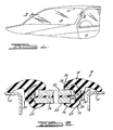
- Figure 1 is a perspective view illustrating a reveal molding of the present invention in place about the periphery of a windshield of an automotive vehicle.
- Figure 2 is a sectional view, broken away, taken along line 2-2 in Figure 1 and showing a preferred embodiment of a reveal molding of the present invention.
- Figure 3 is a cross-sectional view, broken away, of an alternative preferred embodiment of a reveal molding of the present invention in place about a windshield.
- Figure 4 is a cross-sectional view of the molding of Figure 4 in a relaxed condition.
- FIG. 1 shows clamp-on glass molding 10 in operative association with automobile 12 as a windshield reveal molding.
- the clamp-on glass molding 10 extends around the sides and top of windshield 14 to cover the space between a conventionally installed windshield 14 and the body panel 15 of automobile 12.
- clamp-on glass molding 10 is well-suited for use as an automotive windshield reveal molding or backlite reveal molding but also has molding uses both inside and outside the automotive field.
- Clamp-on glass molding 10 is comprised of a suitable elastomeric material and is an elongated molding broadly comprising, in cross-section, a C-shaped clamping portion 16 and a bridging portion or crown 18, both of which can be comprised of polyvinylchloride or other suitable elastomeric material as is common in the art.
- clamping portion 16 and crown 18 can be coextruded and comprised of polyvinylchloride of a hardness of durometer shore A 90 and 85 respectively.
- C-shaped clamping portion 16 has about an equal amount of mass above and below the central plane of the glass windshield 14. This allows for even clamping pressure on opposite surfaces 20 and 22 by limbs or legs 24 and 26 of C-shaped clamping portion 16. This equalized pressure or force of the C-shaped clamping portion 16 reduces the problem of gapping and twisting around the periphery of the windshield and enhances retention of the molding on the windshield without rolling or gapping of the molding. Thus, problems with respect to detachment of the molding from the glass edge or a rolling of the molding away from the glass edge are minimized.
- An adhesive 28 such as a hot melt adhesive can be provided for additional retention of clamp-on glass molding 10 on the edge of windshield 14.
- the C-shaped clamping portion 16 also includes a bottom nip 29.
- the bottom nip 29 is located on the neutral axis of the clamp-on glass molding 10 when applied to the windshield 14.
- the bottom nip 17 allows the adhesive 28 to flow around the bottom nip 17 to mechanically lock the clamp-on glass molding 10 in place when the adhesive 28 hardens.
- Crown 18 provides an umbrella-shaped cover which extends across the space between windshield 14 and the adjacent vehicle body 12. Crown 18 must be resilient and flexible so as to maintain an overlaying engagement with the associated vehicle body which may not always be in exact alignment. Crown 18 also has a stabilizing tail 30 extending downwardly from the laterally median portion of crown 18 as viewed in Figure 2. Tail 30 enhances the resistance of crown 18 to twisting and hence detachment of crown 18 from the glass panel or body panel surface. Tail 30 nests with clamping portion 18 when installed about a windshield. Thus, facing surfaces 32 of crown 18 and 34 of clamping portion 16 are generally contiguous when clamp-on molding 10 is installed. Crown 18 is joined to clamping portion 16 at end 38 of leg 24 of clamping portion 16. The outwardly facing surface 36 of crown 18 can carry a metallized mylar or other bright work as is conventional in the art.
- Clamp-on molding 10 is well-adapted to be a windshield reveal molding.
- Clamp-on molding 10 can accommodate uneven edges of glass, as is illustrated in Figure 2 and as is only found in the art, without being twisted or otherwise disengaged.
- clamp-on molding 10 can be easily installed and is stable once installed to resist disengagement due to temperature extremes, wind, or the like.
- Clamping portion 16 uniformly engages the glass panel edge while crown 18 uniformly covers the space between the glass panel edge and the body panel edge.
- Clamp-on glass molding 100 is shown in Figure 3 in operative association with an automotive vehicle body panel 112 and an automotive windshield 114.
- Clamp-on glass molding 100 broadly comprises a C-shaped clamping portion 116 and a bridging portion or crown 118.
- C-shaped clamping portion 116 has arcuate legs 124 and 126 which have end surfaces 128 and 130 clampingly engaged against opposing surfaces 120 and 122 of windshield 114.
- C-shaped clamping portion 116 is analogous in form and function to clamping portion 16 of clamp-on glass molding 10 and is symmetrical in cross-section with about an equal amount of mass above and below the central plane of windshield 114.
- the C-shaped clamping portion 126 includes a bottom nip 129. The bottom nip 129 allows the windshield adhesive bonding material to flow around the bottom nip 129 to mechanically lock the clamp-on glass molding 100 in place when the adhesive material hardens.
- Crown 118 is generally umbrella-shaped and has a stabilizing tail 132.
- Tail 132 joins crown 118 to C-shaped clamping section 116 along the central axis thereof so that any forces imparted by crown 118 through tail 132 to C-shaped clamping portion 116 will be applied along the central axis.
- Tail 132 has an arcuate shoulder 134 which nestingly receives a corresponding arcuate portion 136 of leg 124 of C-shaped clamping portion 116.
- Surface 138 of leg 124 provides a substantially continuous curved surface with surface 140 of crown 118.
- the moulding in combination with the glazing material may be secured in the window frame by conventional means.
Landscapes
- Engineering & Computer Science (AREA)
- Mechanical Engineering (AREA)
- Transportation (AREA)
- Window Of Vehicle (AREA)
- Securing Of Glass Panes Or The Like (AREA)
- Joining Of Glass To Other Materials (AREA)
- Connection Of Plates (AREA)
Description
- The present invention relates generally to edge moldings for winds panels. More particularly, the present invention relates to a molding for a fixed window of an automobile vehicle such as a windshield or backlite. The molding bridges the space between the edge of the window panel and the adjacent body panel.
- Automotive windshields and backlites are commonly mounted to the associated vehicle body in a manner which leaves a space between the periphery of the glass panel and the body panel. This space is covered by a molding referred to as a windshield or backlite reveal molding. In covering the space between the glass panel and vehicle body, a reveal molding serves to improve the visual appearance of the automotive vehicle and reduce wind noise.
- To present the best visual appearance, reveal moldings must extend evenly around the space between the glass panel and body panel and must be able to accommodate spaces having varying widths. Reveal moldings should also be able to curve around the radius of the glass panel without detaching from the edge of the glass panel or twisting to become disengaged from the glass panel or body panel. Reveal moldings also should resist fluttering in the relative wind.
- Many molding designs for attachment to the edges of automotive glass panels are of a single piece, asymmetrical construction. For example GB-A-1308313 discloses a moulding having a channel portion dimensioned to embrace the edge of glass of a vehicle window, which channel portion has a rear and a front wall, and a front strip portion which has a free end extending beyond the channel portion being free to be flexed away from the front channel wall. When such moldings are attached around a glass panel edge the clamping pressure of the two opposing molding surfaces is uneven due to the difference of resistance between the mass of material above and below the centre axis of the glass. This difference in resistance can cause gapping of one gripper or the other resulting in a loss of uniform gripping about the edge. Loss of gripping can result in detachment of the molding from the glass edge and a rolling of the molding away from the surface of the glass or from the surface of the vehicle body. This result is unsightly and defeats the cosmetic function of the molding as well as increasing the possibility of the molding becoming snagged and pulled out.
- According to the present invention there is provided a resilient, elongate moulding for clamping around the edge region of a fixed piece of glazing material and sealing said piece of glazing material in a frame defining a window, said moulding comprising, in cross-section:
- (i) a clamping portion having two oppositely disposed limbs capable of gripping between them the edge region of the glazing material; and
- (ii) a bridging portion bridging, in use, between the clamping portion and the window frame and being pivotable about the clamping portion,
the moulding being characterised in that it additionally comprises: - (iii) a stabilising tail formed with the bridging portion and, in use, abutting the clamping portion to stabilise the bridging portion in relation to the clamping portion.
- In accordance with the present invention, a glass reveal molding can have a symmetrical generally C-shaped clamping portion which has a substantially equal amount of mass above and below its centre clamping axis and exerts substantially even gripping pressure on both top and bottom surfaces of the glass. The equalized pressure of the clamping portion will substantially eliminate gapping around the glass edge and retain the molding on the windshield without gapping or rolling of the molding. The molding also has a crown or bridging portion with a stabilizing tail that nests with the C-shaped clamping portion. The tail stabilizer prevents the crown from tilting up or down around the radius of the glass but the tail stabilizer allows the crown to seat against the vehicle body. This is achieved because the tail stabilizer presses against the C-shaped clamping portion when the molding is applied around a glass edge. Without the tail stabilizer the crown would tip up or down when the molding is applied around a glass edge.
- Further understanding of the present invention will be had from the following description of preferred embodiments taken in conjunction with the attached drawings and appended claims.
- Figure 1 is a perspective view illustrating a reveal molding of the present invention in place about the periphery of a windshield of an automotive vehicle.
- Figure 2 is a sectional view, broken away, taken along line 2-2 in Figure 1 and showing a preferred embodiment of a reveal molding of the present invention.
- Figure 3 is a cross-sectional view, broken away, of an alternative preferred embodiment of a reveal molding of the present invention in place about a windshield.
- Figure 4 is a cross-sectional view of the molding of Figure 4 in a relaxed condition.
- Now referring to Figures 1 and 2, a preferred embodiment of a clamp-on glass molding of the present invention is illustrated and indicated generally by the
numeral 10. Figure 1 shows clamp-onglass molding 10 in operative association withautomobile 12 as a windshield reveal molding. As shown in Figure 2 the clamp-onglass molding 10 extends around the sides and top ofwindshield 14 to cover the space between a conventionally installedwindshield 14 and thebody panel 15 ofautomobile 12. It will, of course, be appreciated by those skilled in the art that clamp-onglass molding 10 is well-suited for use as an automotive windshield reveal molding or backlite reveal molding but also has molding uses both inside and outside the automotive field. - Clamp-on
glass molding 10 is comprised of a suitable elastomeric material and is an elongated molding broadly comprising, in cross-section, a C-shaped clamping portion 16 and a bridging portion or crown 18, both of which can be comprised of polyvinylchloride or other suitable elastomeric material as is common in the art. For example, clampingportion 16 and crown 18 can be coextruded and comprised of polyvinylchloride of a hardness of durometer shore A 90 and 85 respectively. - C-
shaped clamping portion 16 has about an equal amount of mass above and below the central plane of theglass windshield 14. This allows for even clamping pressure onopposite surfaces legs shaped clamping portion 16. This equalized pressure or force of the C-shaped clamping portion 16 reduces the problem of gapping and twisting around the periphery of the windshield and enhances retention of the molding on the windshield without rolling or gapping of the molding. Thus, problems with respect to detachment of the molding from the glass edge or a rolling of the molding away from the glass edge are minimized. An adhesive 28 such as a hot melt adhesive can be provided for additional retention of clamp-onglass molding 10 on the edge ofwindshield 14. The C-shaped clamping portion 16 also includes abottom nip 29. Thebottom nip 29 is located on the neutral axis of the clamp-onglass molding 10 when applied to thewindshield 14. The bottom nip 17 allows theadhesive 28 to flow around the bottom nip 17 to mechanically lock the clamp-onglass molding 10 in place when theadhesive 28 hardens. - Crown 18 provides an umbrella-shaped cover which extends across the space between
windshield 14 and theadjacent vehicle body 12. Crown 18 must be resilient and flexible so as to maintain an overlaying engagement with the associated vehicle body which may not always be in exact alignment. Crown 18 also has a stabilizing tail 30 extending downwardly from the laterally median portion of crown 18 as viewed in Figure 2. Tail 30 enhances the resistance of crown 18 to twisting and hence detachment of crown 18 from the glass panel or body panel surface. Tail 30 nests with clamping portion 18 when installed about a windshield. Thus, facing surfaces 32 of crown 18 and 34 ofclamping portion 16 are generally contiguous when clamp-onmolding 10 is installed. Crown 18 is joined to clampingportion 16 atend 38 ofleg 24 ofclamping portion 16. The outwardly facingsurface 36 of crown 18 can carry a metallized mylar or other bright work as is conventional in the art. - Clamp-on
molding 10 is well-adapted to be a windshield reveal molding. Clamp-onmolding 10 can accommodate uneven edges of glass, as is illustrated in Figure 2 and as is only found in the art, without being twisted or otherwise disengaged. Furthermore clamp-onmolding 10 can be easily installed and is stable once installed to resist disengagement due to temperature extremes, wind, or the like. Clampingportion 16 uniformly engages the glass panel edge while crown 18 uniformly covers the space between the glass panel edge and the body panel edge. - Now referring to Figures 3 and 4 an alternative embodiment of the present invention is illustrated and indicated generally by the
numeral 100. Clamp-onglass molding 100 is shown in Figure 3 in operative association with an automotivevehicle body panel 112 and anautomotive windshield 114. Clamp-onglass molding 100 broadly comprises a C-shaped clamping portion 116 and a bridging portion orcrown 118. - C-
shaped clamping portion 116 hasarcuate legs end surfaces opposing surfaces 120 and 122 ofwindshield 114. C-shaped clamping portion 116 is analogous in form and function to clampingportion 16 of clamp-onglass molding 10 and is symmetrical in cross-section with about an equal amount of mass above and below the central plane ofwindshield 114. The C-shaped clamping portion 126 includes abottom nip 129. Thebottom nip 129 allows the windshield adhesive bonding material to flow around thebottom nip 129 to mechanically lock the clamp-onglass molding 100 in place when the adhesive material hardens. - Crown 118 is generally umbrella-shaped and has a stabilizing
tail 132.Tail 132 joinscrown 118 to C-shapedclamping section 116 along the central axis thereof so that any forces imparted bycrown 118 throughtail 132 to C-shapedclamping portion 116 will be applied along the central axis.Tail 132 has an arcuate shoulder 134 which nestingly receives a correspondingarcuate portion 136 ofleg 124 of C-shapedclamping portion 116.Surface 138 ofleg 124 provides a substantially continuous curved surface withsurface 140 ofcrown 118. - While the above description sets forth preferred embodiments of the present invention, it will be apparent to those skilled in the art that the present invention is subject to modification and variation within the scope of the following claims.
- The moulding in combination with the glazing material may be secured in the window frame by conventional means.
Claims (9)
- A resilient, elongate moulding (10 or 100) for clamping around the edge region of a fixed piece of glazing material (14 or 114) and sealing said piece of glazing material in a frame (15 or 112) defining a window, said moulding (10 or 100) comprising, in cross-section:(i) a clamping portion (16 or 116) having two oppositely disposed limbs (24, 26 or 124, 126) capable of gripping between them the edge region of the glazing material; and(ii) a bridging portion (18 or 118) bridging, in use, between the clamping portion (16 or 116) and the window frame (15 or 112) and being pivotable about the clamping portion (16 or 116),
the moulding being characterised in that it additionally comprises:(iii) a stabilising tail (30 or 132) formed with the bridging portion (18 or 118) and, in use, abutting the clamping portion (16 or 116) to stabilise the bridging portion (18 or 118) in relation to the clamping portion (16 or 116). - A moulding (10) according to claim 1, wherein the bridging portion (18) is joined to an end portion of one limb (24) of the clamping portion (16).
- A moulding (100) according to claim 1, wherein the bridging portion (118) is joined to the clamping portion (116) at a central axis thereof.
- A moulding (100) according to claim 3, wherein the outer surface (140), in use with respect to the window, of the bridging portion (118) extends continuously with a portion (138) of an outer surface of one of the clamping limbs (124).
- A moulding (10 or 100) according to any preceding claim, wherein the clamping portion (16 or 116) is attached to the edge region of the glazing material (14 or 114) with an adhesive.
- A moulding (10 or 100) according to any preceding claim, wherein the clamping portion (16 or 116) is generally C-shaped.
- A moulding (10 or 100) according to any preceding claim, wherein the bridging portion (18 or 118) is generally umbrella-shaped.
- A moulding according to any preceding claim, wherein the stabilizing portion (30 or 132) lies in nesting relationship with the clamping portion (16 or 116) when the moulding is in use.
- A moulding according to any one of claims 1 to 8 in combination with a vehicle body (12) having a frame (15 or 112) defining a window into which is received a piece of glazing material (14 or 114) around the periphery of which the moulding (10 or 110) is secured.
Applications Claiming Priority (2)
| Application Number | Priority Date | Filing Date | Title |
|---|---|---|---|
| US102385 | 1987-09-29 | ||
| US07/102,385 US4813733A (en) | 1987-09-29 | 1987-09-29 | Clamp-on glass molding |
Publications (3)
| Publication Number | Publication Date |
|---|---|
| EP0310226A2 EP0310226A2 (en) | 1989-04-05 |
| EP0310226A3 EP0310226A3 (en) | 1990-08-29 |
| EP0310226B1 true EP0310226B1 (en) | 1993-08-25 |
Family
ID=22289559
Family Applications (1)
| Application Number | Title | Priority Date | Filing Date |
|---|---|---|---|
| EP88307015A Expired - Lifetime EP0310226B1 (en) | 1987-09-29 | 1988-07-29 | Clamp-on glass moulding |
Country Status (9)
| Country | Link |
|---|---|
| US (1) | US4813733A (en) |
| EP (1) | EP0310226B1 (en) |
| JP (1) | JPH01115722A (en) |
| KR (1) | KR890004920A (en) |
| AR (1) | AR241132A1 (en) |
| AU (1) | AU622868B2 (en) |
| BR (1) | BR8804650A (en) |
| CA (1) | CA1316966C (en) |
| DE (1) | DE3883469D1 (en) |
Families Citing this family (20)
| Publication number | Priority date | Publication date | Assignee | Title |
|---|---|---|---|---|
| US4996808A (en) * | 1987-01-02 | 1991-03-05 | Libbey-Owens-Ford Co. | Encapsulated window assembly |
| US4905432A (en) * | 1988-03-03 | 1990-03-06 | Navistar International Transportation Corp. | Windshield glass and trim assembly and method for making same |
| JP2839890B2 (en) * | 1988-08-27 | 1998-12-16 | 東海興業株式会社 | Manufacturing method of glass-vinyl chloride resin integrated molding |
| US4916873A (en) * | 1989-02-06 | 1990-04-17 | The Standard Products Company | Windshield reveal molding with core structure |
| US5001876A (en) * | 1989-03-03 | 1991-03-26 | The Standard Products Company | Flush glass windshield reveal molding |
| US5032444A (en) * | 1990-03-19 | 1991-07-16 | The Standard Products Company | Reveal molding |
| US5137323A (en) * | 1991-04-12 | 1992-08-11 | Creative Extruded Products Inc. | Decorative molding and method of manufacture |
| US5311711A (en) * | 1992-10-30 | 1994-05-17 | Standard Products Company | J-type window lace assemblies |
| US5338087A (en) * | 1993-03-24 | 1994-08-16 | Creative Extruded Products, Inc. | Anti-squeak molding |
| US5331767A (en) * | 1993-03-24 | 1994-07-26 | The Standard Products Company | Enhanced weatherstrip mounted on glass with opposite side seal |
| US5396746A (en) * | 1994-01-07 | 1995-03-14 | Whitmer; Bruce F. | Molding construction |
| US5423147A (en) * | 1994-02-17 | 1995-06-13 | Gencorp Inc. | Wireless carrier weatherstrip seal |
| US5429844A (en) * | 1994-05-24 | 1995-07-04 | The Standard Products Company | Reveal molding with coacting gripping structure |
| US5626383A (en) * | 1994-12-28 | 1997-05-06 | Gencorp Inc. | Wireless weatherstrip profiles |
| US6257643B1 (en) * | 2000-01-20 | 2001-07-10 | Creative Extruded Products, Inc. | Window trim molding with adhesion promoter |
| DE10103865C1 (en) * | 2001-01-30 | 2002-05-02 | Saint Gobain Sekurit D Gmbh | Formation of edging profile on a pane of two sheets of glass held together by an adhesive, comprises forming the edging on a pane whose shape is determined by the shape of a molding bed, no adhesion promoter being present on edge of pane |
| KR200234004Y1 (en) | 2001-03-03 | 2001-09-28 | 임흥빈 | Tempered glass door safety tool with windproof soundproofing and safety |
| US6487823B2 (en) | 2001-03-05 | 2002-12-03 | Centre Luxembourgeois De Recherches Pour Le Verre Et La Ceramique S.A. | Vehicle window glazing edge seal profile |
| KR100916709B1 (en) * | 2007-08-21 | 2009-09-11 | 한국수자원공사 | Non-powered tube mixing device |
| JP4847989B2 (en) * | 2008-07-17 | 2011-12-28 | 株式会社シューユウ | Light control and polarization lens for sunglasses |
Family Cites Families (11)
| Publication number | Priority date | Publication date | Assignee | Title |
|---|---|---|---|---|
| US2736404A (en) * | 1952-06-19 | 1956-02-28 | Gen Motors Corp | Sealing strip |
| US2763345A (en) * | 1953-06-09 | 1956-09-18 | Gen Motors Corp | Connector strip |
| GB1308313A (en) * | 1969-03-21 | 1973-02-21 | Creators Ltd | Trim strips for use in glazing window or windscreen openings parti cularly in vehicle bodies |
| US3705470A (en) * | 1969-03-21 | 1972-12-12 | Creators Ltd | Glazing windows or windscreen openings, particularly in vehicle bodies |
| US4165119A (en) * | 1977-11-23 | 1979-08-21 | General Motors Corporation | Window reveal molding |
| DE2818755A1 (en) * | 1978-04-28 | 1979-11-08 | Daimler Benz Ag | Seal strip for windscreen - incorporating grooves around glass edge to act as LF vibration dampers |
| US4358917A (en) * | 1981-05-11 | 1982-11-16 | Chrysler Corporation | Self-adjustable window molding for retaining glass |
| JPS60163720A (en) * | 1984-02-07 | 1985-08-26 | Kinugawa Rubber Ind Co Ltd | Flush mount weather strip installing construction |
| JPS61132411A (en) * | 1984-11-30 | 1986-06-19 | Shiraki Kinzoku Kogyo Kk | Molding |
| IT8522038V0 (en) * | 1985-05-31 | 1985-05-31 | Siv Soc Italiana Vetro | GLASS FOR VEHICLES PARTICULARLY SUITABLE FOR APPLICATION WITH AUTOMATIC VEHICLES ON ITS SUPPORT FRAME. |
| JPH0624884B2 (en) * | 1985-12-28 | 1994-04-06 | 日産自動車株式会社 | Corner-moor mounting structure for automobile windmills |
-
1987
- 1987-09-29 US US07/102,385 patent/US4813733A/en not_active Expired - Fee Related
-
1988
- 1988-07-27 CA CA000573169A patent/CA1316966C/en not_active Expired - Fee Related
- 1988-07-29 EP EP88307015A patent/EP0310226B1/en not_active Expired - Lifetime
- 1988-07-29 DE DE88307015T patent/DE3883469D1/en not_active Expired - Lifetime
- 1988-08-22 AU AU21182/88A patent/AU622868B2/en not_active Ceased
- 1988-09-09 BR BR8804650A patent/BR8804650A/en not_active IP Right Cessation
- 1988-09-27 JP JP63242191A patent/JPH01115722A/en active Pending
- 1988-09-28 KR KR1019880012564A patent/KR890004920A/en not_active Withdrawn
- 1988-09-28 AR AR312067A patent/AR241132A1/en active
Also Published As
| Publication number | Publication date |
|---|---|
| KR890004920A (en) | 1989-05-10 |
| AR241132A2 (en) | 1991-11-29 |
| JPH01115722A (en) | 1989-05-09 |
| AR241132A1 (en) | 1991-11-29 |
| AU2118288A (en) | 1989-04-06 |
| AU622868B2 (en) | 1992-04-30 |
| DE3883469D1 (en) | 1993-09-30 |
| BR8804650A (en) | 1989-04-18 |
| EP0310226A3 (en) | 1990-08-29 |
| CA1316966C (en) | 1993-04-27 |
| EP0310226A2 (en) | 1989-04-05 |
| US4813733A (en) | 1989-03-21 |
Similar Documents
| Publication | Publication Date | Title |
|---|---|---|
| EP0310226A2 (en) | Clamp-on glass moulding | |
| US5001876A (en) | Flush glass windshield reveal molding | |
| US5032444A (en) | Reveal molding | |
| US4843763A (en) | Window seal and guide for flush mounted windows | |
| US5040333A (en) | Movable flush-glass system for an automobile door | |
| EP0587428B1 (en) | Window enclosures for automobile doors | |
| EP0794078B1 (en) | Sealing, trimming and finishing strips | |
| US4470223A (en) | Seals for sliding automobile windows | |
| US5027556A (en) | Window sealing and guiding arrangements | |
| IT8224716A1 (en) | GASKET PROFILE FOR WINDOW FRAMES | |
| US3514916A (en) | Sealing strip | |
| JPH0238405B2 (en) | ||
| US4916873A (en) | Windshield reveal molding with core structure | |
| GB2093106A (en) | Structure for fixing window glass panes | |
| EP0859705A1 (en) | Window with glazing profile | |
| US5429844A (en) | Reveal molding with coacting gripping structure | |
| KR101173052B1 (en) | Door frame assembly | |
| EP0573139B1 (en) | Sealing and guiding arrangements | |
| EP0691231B1 (en) | Window glass sealing and fixing arrangements | |
| EP0246008B1 (en) | Weatherstrip | |
| GB2411924A (en) | Window pane support strip | |
| CA1322019C (en) | Glass run molding | |
| KR20000069021A (en) | Adjustable glazing for motor vehicles | |
| CN223735813U (en) | Frameless front triangular window | |
| JPS6232892Y2 (en) |
Legal Events
| Date | Code | Title | Description |
|---|---|---|---|
| PUAI | Public reference made under article 153(3) epc to a published international application that has entered the european phase |
Free format text: ORIGINAL CODE: 0009012 |
|
| AK | Designated contracting states |
Kind code of ref document: A2 Designated state(s): DE ES FR GB IT |
|
| PUAL | Search report despatched |
Free format text: ORIGINAL CODE: 0009013 |
|
| AK | Designated contracting states |
Kind code of ref document: A3 Designated state(s): DE ES FR GB IT |
|
| 17P | Request for examination filed |
Effective date: 19901019 |
|
| 17Q | First examination report despatched |
Effective date: 19920206 |
|
| GRAA | (expected) grant |
Free format text: ORIGINAL CODE: 0009210 |
|
| AK | Designated contracting states |
Kind code of ref document: B1 Designated state(s): DE ES FR GB IT |
|
| PG25 | Lapsed in a contracting state [announced via postgrant information from national office to epo] |
Ref country code: IT Free format text: LAPSE BECAUSE OF FAILURE TO SUBMIT A TRANSLATION OF THE DESCRIPTION OR TO PAY THE FEE WITHIN THE PRE;WARNING: LAPSES OF ITALIAN PATENTS WITH EFFECTIVE DATE BEFORE 2007 MAY HAVE OCCURRED AT ANY TIME BEFORE 2007. THE CORRECT EFFECTIVE DATE MAY BE DIFFERENT FROM THE ONE RECORDED.SCRIBED TIME-LIMIT Effective date: 19930825 Ref country code: DE Effective date: 19930825 Ref country code: FR Effective date: 19930825 Ref country code: ES Free format text: THE PATENT HAS BEEN ANNULLED BY A DECISION OF A NATIONAL AUTHORITY Effective date: 19930825 |
|
| REF | Corresponds to: |
Ref document number: 3883469 Country of ref document: DE Date of ref document: 19930930 |
|
| EN | Fr: translation not filed | ||
| PLBE | No opposition filed within time limit |
Free format text: ORIGINAL CODE: 0009261 |
|
| STAA | Information on the status of an ep patent application or granted ep patent |
Free format text: STATUS: NO OPPOSITION FILED WITHIN TIME LIMIT |
|
| 26N | No opposition filed | ||
| PGFP | Annual fee paid to national office [announced via postgrant information from national office to epo] |
Ref country code: GB Payment date: 19950619 Year of fee payment: 8 |
|
| PG25 | Lapsed in a contracting state [announced via postgrant information from national office to epo] |
Ref country code: GB Effective date: 19960729 |
|
| GBPC | Gb: european patent ceased through non-payment of renewal fee |
Effective date: 19960729 |