EP0309627A1 - Appareil de connexion d'un équipement de traitement de données au réseau téléphonique - Google Patents
Appareil de connexion d'un équipement de traitement de données au réseau téléphonique Download PDFInfo
- Publication number
- EP0309627A1 EP0309627A1 EP87308679A EP87308679A EP0309627A1 EP 0309627 A1 EP0309627 A1 EP 0309627A1 EP 87308679 A EP87308679 A EP 87308679A EP 87308679 A EP87308679 A EP 87308679A EP 0309627 A1 EP0309627 A1 EP 0309627A1
- Authority
- EP
- European Patent Office
- Prior art keywords
- code
- standard
- coupler
- identifier
- modem
- Prior art date
- Legal status (The legal status is an assumption and is not a legal conclusion. Google has not performed a legal analysis and makes no representation as to the accuracy of the status listed.)
- Granted
Links
- 238000012545 processing Methods 0.000 title claims abstract description 27
- 238000004891 communication Methods 0.000 claims abstract description 21
- 230000008878 coupling Effects 0.000 claims description 9
- 238000010168 coupling process Methods 0.000 claims description 9
- 238000005859 coupling reaction Methods 0.000 claims description 9
- 230000006870 function Effects 0.000 description 12
- 238000000034 method Methods 0.000 description 9
- 230000001419 dependent effect Effects 0.000 description 5
- 230000008569 process Effects 0.000 description 5
- 230000005540 biological transmission Effects 0.000 description 4
- 238000011905 homologation Methods 0.000 description 3
- 230000004913 activation Effects 0.000 description 2
- 230000008901 benefit Effects 0.000 description 2
- 238000006243 chemical reaction Methods 0.000 description 2
- 238000004519 manufacturing process Methods 0.000 description 2
- 230000007246 mechanism Effects 0.000 description 2
- 230000004048 modification Effects 0.000 description 2
- 238000012986 modification Methods 0.000 description 2
- 239000004065 semiconductor Substances 0.000 description 2
- 238000012546 transfer Methods 0.000 description 2
- 235000001537 Ribes X gardonianum Nutrition 0.000 description 1
- 235000001535 Ribes X utile Nutrition 0.000 description 1
- 235000016919 Ribes petraeum Nutrition 0.000 description 1
- 244000281247 Ribes rubrum Species 0.000 description 1
- 235000002355 Ribes spicatum Nutrition 0.000 description 1
- 238000013459 approach Methods 0.000 description 1
- 230000004888 barrier function Effects 0.000 description 1
- 230000002457 bidirectional effect Effects 0.000 description 1
- 230000003139 buffering effect Effects 0.000 description 1
- 238000010276 construction Methods 0.000 description 1
- 238000010586 diagram Methods 0.000 description 1
- 238000002955 isolation Methods 0.000 description 1
- 238000012536 packaging technology Methods 0.000 description 1
- 238000007639 printing Methods 0.000 description 1
- ZYHMJXZULPZUED-UHFFFAOYSA-N propargite Chemical compound C1=CC(C(C)(C)C)=CC=C1OC1C(OS(=O)OCC#C)CCCC1 ZYHMJXZULPZUED-UHFFFAOYSA-N 0.000 description 1
- 230000001681 protective effect Effects 0.000 description 1
Images


Classifications
-
- H—ELECTRICITY
- H04—ELECTRIC COMMUNICATION TECHNIQUE
- H04M—TELEPHONIC COMMUNICATION
- H04M11/00—Telephonic communication systems specially adapted for combination with other electrical systems
- H04M11/06—Simultaneous speech and data transmission, e.g. telegraphic transmission over the same conductors
-
- H—ELECTRICITY
- H04—ELECTRIC COMMUNICATION TECHNIQUE
- H04L—TRANSMISSION OF DIGITAL INFORMATION, e.g. TELEGRAPHIC COMMUNICATION
- H04L27/00—Modulated-carrier systems
- H04L27/10—Frequency-modulated carrier systems, i.e. using frequency-shift keying
-
- Y—GENERAL TAGGING OF NEW TECHNOLOGICAL DEVELOPMENTS; GENERAL TAGGING OF CROSS-SECTIONAL TECHNOLOGIES SPANNING OVER SEVERAL SECTIONS OF THE IPC; TECHNICAL SUBJECTS COVERED BY FORMER USPC CROSS-REFERENCE ART COLLECTIONS [XRACs] AND DIGESTS
- Y10—TECHNICAL SUBJECTS COVERED BY FORMER USPC
- Y10S—TECHNICAL SUBJECTS COVERED BY FORMER USPC CROSS-REFERENCE ART COLLECTIONS [XRACs] AND DIGESTS
- Y10S379/00—Telephonic communications
- Y10S379/912—Geographically adaptive
Definitions
- This invention relates to apparatus for connecting data processing equipment, such as personal computers, word processors or other workstations, to a communications network to communicate with other data processing equipment.
- National communications networks have different "national" requirements (hereinafter referred to as standards) standards from one another, whether they be digital networks or analogue networks, the most common of which is the telephone system.
- the telephone system exemplifies how standards vary from country to country.
- modem When data processing equipment is connected to an analogue network such as the telephone system, use is made of a modem.
- the purpose of the modem is to convert the digital data stream within the data processing equipment into a form which is suitable for transmission over a telephone network, and vice versa.
- US Patent No. 4,431,867 describes a typical modern modem in which the various functions of the modem are operated under the control of a digital microprocessor with a read only memory containing control code.
- command mode in which the modem will respond to commands prior to and after transmitting or receiving data
- data mode in which the modem will perform basic modulation and demodulation functions.
- command mode in which the modem will respond to commands prior to and after transmitting or receiving data
- data mode in which the modem will perform basic modulation and demodulation functions.
- it provides a connection between a standard telephone network and a standard data port.
- Equipment will not normally be approved by a PTT if it is capable of issuing "incorrect” signals and to this extent the equipment should be “tamper proof", that is it should not be possible for some unauthorised person to tamper with the equipment so that it no longer conforms to the particular network standards.
- An object of the present invention is to provide apparatus which is suitable to connect data processing equipment to a plurality of different communications networks and which is automatically configured to the appropriate standard when connected to a network coupler.
- apparatus for connecting data processing equipment to a communication network includes circuits for transmitting and/or receiving signals between the data processing equipment and the communications network and a digital signal processing means for controlling the operation of said transmitting/receiving circuits in accordance with control code stored in a control store, and means for coupling the equipment to the network, and is characterised in that said apparatus includes common hardware for a range of different network standards, in that said coupling means contains an identifier for identifying which network is to be connected to the equipment, and in that said apparatus is configured to the standard of a particular network when the coupling means is connected to the apparatus.
- a coupler for connecting data processing equipment including to a communications network comprises a plug for connecting the coupler to a standard socket within a country and a connector for attaching the coupler to the data processing equipment and is characterised in that the coupler includes a country identifier code for configuring the apparatus to operate in a manner to comply with that particular country standard.
- a modem constructed so that when it is first connected to a country-specific modem-to-telephone line coupler, a code which is unique to that particular coupler is read into the control code store thereby automatically allocating specific country parameters to configure the modem to a particular telephone network standard: thereafter each time the modem is powered on, a check is made to determine whether the coupler in use is compatible with the stored control code and, if it is not, the modem is inhibited from operation. If it were desired to re-configure a modem to a new standard, it is preferred that this could only be done in an authorised manner using a new telephone line coupler since this will ease the problem of homologation of the equipment.
- control code store which in this event could be a read only memory
- the access by the digital signal processor to the control code store being controlled by the coupler identifier information.
- Figure 1 serves to illustrate the basic principles underlying the present invention where it is desired to connect data processing equipment 1 to the public telephone network 2.
- the invention uses a modem 3 which contains all the control and signal processing circuits and hardware which is common to all countries to which it is desired to connect.
- a modem-to-telephone line coupler 4 connects the modem 3 to the telephone line 2 via plug and socket connections 5 and 6.
- the coupler 4 contains the hardware (for example resistors, relays) which is unique to a particular country and has the standard telephone plug 6 for that particular country.
- the coupler 4 contains an identifier which defines the particular country and which automatically allows the modem 3 to be configured to that particular country's telephone line and CCITT (Comite Consultatif International Circuitique et Telephonique) standards.
- CCITT Computer Consultatif International Circuitique et Telephonique
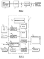
- Figure 2 illustrates how the invention may be implemented in a personal computer such as the IBM Personal Computer XT or AT or Personal System/2.
- the personal computer includes a system unit 7 containing a microprocessor 8.
- a system unit 7 containing a microprocessor 8.
- a read only store 10 containing control code for operating the microprocessor 8
- a random access memory 11 for containing code and/or data for use during operation of the personal computer
- a display adapter 12 for displaying data as a display device 13, normally a raster-scanned cathode ray tube display
- a printer adapter 14 to allow the printing of data on an attached printer 15.
- Diskette drive 17 may be replaced or supplemented by a hard disk file, not shown.
- Keyboard adapter 18 allows keyboards 19 to enter data and/or commands into the computer by the operator and communications adapter 20 allows communication over a data link 21 to a remote data processor. Construction and operations of these various adapters are well known and will not be described except to say that they each provide the correct interface with the external devices and also any necessary buffering or signal processing requirements.
- the modem 3 which is connectable to the public telephone network 2 by the coupler 4.
- the modem 3 could be constructed as a plug-in printed circuit card, it could, in fact be integrated into the main planar board of the personal computer's system unit. This would be cheaper than having a separate pluggable card and is possible because the modem 3 is common to a wide range of countries. As will be explained below, it may be desirable for some parts of the modem 3 to be removed therefrom and incorporated into the coupler 4.
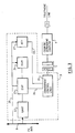
- FIG. 3 shows the modem 3 in more detail and is a preferred embodiment of the invention. Not shown are the various modulating, demodulating, tone generating and other circuits which are well understood by communications engineers since such details would only serve to make the description and drawings unnecessarily lengthy and complex.
- the modem 3 contains all the components which are common to a whole range of countries and includes a universal asynchronous receiver/transmitter (UART) device 22 to which is connected a digital signal processor (DSP) device 23 (frequently known as a programmable signal processor) which performs the modulation and demodulation function.
- UART universal asynchronous receiver/transmitter
- DSP digital signal processor
- the UART and DSP devices 22 and 23 are readily available off-the-shelf semiconductor modules and could, for example, be constituted by the National Semiconductor NS 16450A device for the UART and the Texas Instrument TMS 3290, TMS 320C10, TMS 320C15 devices for the DSP.
- the DSP 23 processes signals presented to it by UART 22 in accordance with the control code (which includes country dependent parameters) stored in random access memory 24. Although only one memory 24 is shown, more than one memory could be used. For example a separate readable store containing common code could be provided. In some circumstances, it may be desirable to include an additional microprocessor within the modem to execute control code in accordance with signals from the UART22 to control the operation of the DSP 23 or alternatively to replace the DSP 23. This additional microprocessor would then relieve the microprocessor of the personal computer of many of the associated tasks.
- memory 24 contains only the code required for the particular country associated with the particular coupler 4 connected to the modem 3 through socket connection 5.
- coupler 4 contains a country identifier which is read by the modem 3 and which is used to load required code into the RAM 24 from the PC system bus 9.
- the coupler 4 acts as a modem adapter cable and, in combination with the modem 3, provides the correct load impedance to match the requirements of the PTT cable 2: coupler 4 performs no modulation or demodulation function.
- the modem 3 includes convertor/control logic unit 25 which reads the country identifier in coupler 4 and compares this with the country identifier of the code stored in the memory 24. If there is inequality, the convertor/control logic unit 25 will not enable the modem.
- the convertor/control logic unit 25 will enable digital signals from the DSP 23 to be converted to analogue signals therein to pass to the coupler 4 via line 26 and socket 5.
- Country identifier code associated with the code stored in the RAM 24 is stored into key register 27 from which it is accessible to control logic 25 via line 28. This sequence is summarised in Figure 4.
- the converter/control logic unit 25 has two main functions. At power on, it reads the country code identifier from the coupler and in conjunction with the DSP 23 checks this against the stored country code. If the check is valid, the modem will be enabled. When the modem is enabled, analogue signals from the telephone line are converted by the unit 25 into digital signals. These digital signals are sampled by the DSP 23 along line 26 in accordance with the country dependent code stored in RAM 24.
- Outgoing signals from the UART 22 are processed by the DSP 23 in accordance with the country dependent control code in RAM 24 and are then passed along line 26 to the converter/control logic unit 25 where they are converted into analogue signals for transmission over the telephone network (but only if the modem has been enabled).
- the country parameters stored in RAM 24 can be loaded therein in a number of ways. It is preferred that when the workstation is being installed or set up, a diskette containing the country code is used to load the code via diskette drive 17, Figure 2, diskette adapter 16, Figure 2, and PC bus 9 under control of the microprocessor 8, Figure 2: this diskette could be a "universal" diskette containing all versions of code in which case provision will be required to identify which code needs to be loaded, or each country-specific coupler 4 could be supplied with an associated country-specific diskette which would be used when the coupler 4 is being connected to the modem. This sequence is summarised in Figure 5.
- the RAM 24 (containing code for a specified country) is replaced by a store (which is preferably a read only store) containing all possibly desired code but the country identifier read by the convertor/control logic unit 25 from the coupler 4 is used to enable the DSP 23 to access only those sections of the read only store which contain control code associated with that country.
- a store which is preferably a read only store
- the modem contains all the common hardware but that this hardware can only be configured in accordance with the country identifier contained within the country-specific coupler 4.
- the identifier read from the coupler 4 by the convertor/control logic unit 25 can be passed to the microprocessor 8, Figure 2, which would then load the appropriate code into RAM 24/register 27 or enable access by the DSP 23 to predetermined sections of the store 24 where this contained all possibly required code.
- a diskette contains the necessary modulation/demodulation code required to meet a country requirement.
- code such as CCITT V22, V21, V26ter, can be downloaded from the diskette to enable the DSP 23 to operate at the above modulation/demodulation speeds.
- Any code contained on a diskette for loading into the modem can be protected against modification or tampering by unauthorised persons, for example by the use of hash sums or equivalent protection techniques.
- control logic When the data processing equipment is not connected to a telephone or other communications network, it may be desirable to load non-communication control code into the control store to allow the DSP 23 to control another function: in this mode the control logic would not allow the equipment to be connected to the communications network.
- the socket/plug 5 has 15 pins for carrying signals as specified below in Table 1.
- the plug to the telephone line will have a number of pins which depends on the country.
- Modern packaging technology is such that in many cases, any country dependent components in the coupler can be encapsulated in the cable itself (to give a so-called "fat" cable).
- the coupler 4 When receiving ring pulse trains from the telephone exchange over the telephone line, the ring detector circuit validates them and lowers RI to the workstation modem hardware.
- the output signal is a rectified RI signal at double the RI frequency at TTL levels.
- the coupler 4 When an attached handset is OFF HOOK, the line currant is detected and the switch hook circuit is activated and set low. The signal is high whenever the attached handset is in the ON HOOK position. The signal is presented to the modem at TTL levels.
- TTL Logic Low selects the Least Significant 1/2 Byte of the country code and TTL Logic High selects the Most Significant 1/2 Byte of the country code - see Table 8 below.
- a +5 V +/- 5% power supply capable of supplying up to 300 mA to the coupler from the workstation modem hardware.
- the code is made up of two 1/2 byte patterns which are selected by the Select Country Code signal.
- the Country Identifier Code is hardwired into each coupler.
- the coupler is country unique by virtue of a unique country-specific plug and a set of components which meet the requirements of that country.
- the identifier code enables "identification" of that unique country by the control logic.
- the code is contained in one byte allowing support for 255 different countries.
- the high or low order 1/2 byte are selected by the country select line.
- the workstation logic can read the code at initialisation or configuration time, and set up appropriate modulation techniques and other parameters specific to the supported network.
- a return code of 1111 (Most Significant 1/2 byte) and 1111 (Least Significant 1/2 byte) may be used to indicate that the coupler is not attached.
- Table 8 COUNTRY LOW 1/2 Byte HIGH 1/2 Byte US 1110 1111 UK 1101 1111 AUSTRIA 1100 1111 BELGIUM 1011 1111 DENMARK 1010 1111 FRANCE 1001 1111 GERMANY 1000 1111 ISRAEL 0111 1111 ITALY 0110 1111 LUXEMBURG 0101 1111 NETHERLANDS 0100 1111 NORWAY 0011 1111 SWEDEN 0010 1111 SWITZERLAND 0001 1111
- Figure 4 is a flow chart illustrating country set-up from the read only storage. The process is invoked each time the equipment is powered on as at step 40. At power on, the modem is reset to operate in a primitive command mode, that is the telephone line attach function is disabled. In step 41, the modem logic unit 25 reads the country identifier code from the coupler and validate this code by checking it against the country code stored within the modem. If the validity check, step 42, indicates non comparison, the modem remains in the primitive mode, that is with the telephone line function disabled, as at step 43. If the validity check is valid, the modem is initialised as at step 44 by selecting the appropriate country parameter table to obtain the control code for correct operation of the modem. In a final step 45, the modem is enabled for full auto answer/call function. The process of Figure 4 is used where the control code is contained in a read only store.
- the modem should only be enabled if the "correct" coupler is connected to it. It is crucial to this process that the "correct" country identifier and control code is stored within the equipment. As explained above, only authorised personnel should be able to modify or enter control code and country codes within the modem.
- Figure 5 is a flow chart illustrating how it can be ensured that when data processing equipment, such as a personal computer, incorporating a modem is set up from a diskette file, checks are made to determine that incorrect control code is not loaded into the modem.
- the equipment is powered on, the modem is reset to primitive mode, that is with the telephone line attach function disabled.
- the country is identified, either from a diskette loaded into the equipment or by operator, to run its PC loader utility from the PC operating system which reads and validates the coupler country identifier. If the result of the validity check 52 is invalidity, the modem is maintained in primitive mode as at 53 with the telephone line disabled. If the country identifier is valid, the modem is initialised at step 54.
- the PC loader utility selects an appropriate country parameter file from the PC disk (or diskette) and transfers it to the modem.
- the modem logic ensures that the country parameters agree with a hash check-sum contained in the parameter file. If as a result of this validity check 56 there is an error, the modem remains in primitive mode with the telephone line disabled, as at step 57: this prevents an operator from loading country parameters which do not correspond to the coupler attached to the equipment (and which is country unique). If the hash check 56 is valid, the modem is enabled as at step 58 to allow full auto answer/call function.
- the couplers for telephone networks could include the digital to analogue and analogue to digital circuits, even if these are common to the whole range of telephone networks.
- practical consideration would normally require the conversion circuits to be within the modem in close proximity to the DSP or the modulation/demodulation unit.
Landscapes
- Engineering & Computer Science (AREA)
- Computer Networks & Wireless Communication (AREA)
- Signal Processing (AREA)
- Communication Control (AREA)
- Telephonic Communication Services (AREA)
Priority Applications (4)
| Application Number | Priority Date | Filing Date | Title |
|---|---|---|---|
| DE87308679T DE3786266T2 (de) | 1987-09-30 | 1987-09-30 | Vorrichtung zum Anschluss einer Datenverarbeitungseinrichtung an ein Telefonnetz. |
| EP87308679A EP0309627B1 (fr) | 1987-09-30 | 1987-09-30 | Appareil de connexion d'un équipement de traitement de données au réseau téléphonique |
| JP63213876A JPH0194757A (ja) | 1987-09-30 | 1988-08-30 | データ処理装置を通信ネツトワークに接続する装置 |
| US07/251,157 US4868863A (en) | 1987-09-30 | 1988-09-29 | Apparatus for connecting data processing equipment to a communication network |
Applications Claiming Priority (1)
| Application Number | Priority Date | Filing Date | Title |
|---|---|---|---|
| EP87308679A EP0309627B1 (fr) | 1987-09-30 | 1987-09-30 | Appareil de connexion d'un équipement de traitement de données au réseau téléphonique |
Publications (2)
| Publication Number | Publication Date |
|---|---|
| EP0309627A1 true EP0309627A1 (fr) | 1989-04-05 |
| EP0309627B1 EP0309627B1 (fr) | 1993-06-16 |
Family
ID=8198055
Family Applications (1)
| Application Number | Title | Priority Date | Filing Date |
|---|---|---|---|
| EP87308679A Expired - Lifetime EP0309627B1 (fr) | 1987-09-30 | 1987-09-30 | Appareil de connexion d'un équipement de traitement de données au réseau téléphonique |
Country Status (4)
| Country | Link |
|---|---|
| US (1) | US4868863A (fr) |
| EP (1) | EP0309627B1 (fr) |
| JP (1) | JPH0194757A (fr) |
| DE (1) | DE3786266T2 (fr) |
Cited By (6)
| Publication number | Priority date | Publication date | Assignee | Title |
|---|---|---|---|---|
| EP0679006A3 (fr) * | 1994-04-22 | 1995-11-29 | Siemens Ag | |
| USRE38645E1 (en) | 1989-01-19 | 2004-11-02 | Mlr, Llc | Portable hybrid communication system and methods |
| USRE39427E1 (en) | 1985-10-11 | 2006-12-12 | Mlr, Llc | Cellular telephone data communication system and method |
| US7248901B2 (en) | 2001-01-18 | 2007-07-24 | Andreas Peiker | Arrangement for handling a communication device |
| US7283849B2 (en) | 2001-01-18 | 2007-10-16 | Andreas Peiker | Assembly comprising a mobile telephone |
| US7603686B2 (en) | 2000-11-30 | 2009-10-13 | Sony Corporation | Information processing method and apparatus and recording medium |
Families Citing this family (60)
| Publication number | Priority date | Publication date | Assignee | Title |
|---|---|---|---|---|
| USRE37141E1 (en) | 1984-09-10 | 2001-04-17 | Spectrum Information Technologies, Inc. | Cellular telephone data communication system and method |
| US4972457A (en) | 1989-01-19 | 1990-11-20 | Spectrum Information Technologies, Inc. | Portable hybrid communication system and methods |
| FR2652173B1 (fr) * | 1989-09-15 | 1994-05-06 | Apple Computer Inc | Dispositif modulateur/demodulateur a configurations variables pour ordinateur ou analogue. |
| DE3942690C2 (de) * | 1989-12-22 | 1999-03-25 | Siemens Ag | Anschlußstecker |
| EP0459279A1 (fr) * | 1990-05-30 | 1991-12-04 | Hayes Microcomputer Products, Inc. | Construction d'un module d'interface de ligne global et appareil de télécommunication l'utilisant |
| US5127041A (en) * | 1990-06-01 | 1992-06-30 | Spectrum Information Technologies, Inc. | System and method for interfacing computers to diverse telephone networks |
| SG42315A1 (en) * | 1990-12-05 | 1997-08-15 | Ibm | Coupling device to be connected to a DCE for the connection to a public switched telephone network having a local power supply circuit for allowing the use of the local |
| DE69026095T2 (de) * | 1990-12-05 | 1996-10-02 | Ibm | Kopplungseinrichtung zum Anschluss einer Datenübertragungs- anschu-einrichtung an verschiedene öffentliche Fernsprechwahlnetzen sowie eine Datenübertragungsanschlu-einrichtung und eine Arbeitsstation mit einer solchen Kopplungseinrichtung |
| US5250940A (en) * | 1991-01-18 | 1993-10-05 | National Semiconductor Corporation | Multi-mode home terminal system that utilizes a single embedded general purpose/DSP processor and a single random access memory |
| FR2677831B1 (fr) * | 1991-06-17 | 1994-12-09 | Apple Computer | Modem a circuit d'interface de ligne perfectionne, notamment pour ordinateur. |
| US5353793A (en) * | 1991-11-25 | 1994-10-11 | Oishi-Kogyo Company | Sensor apparatus |
| US5249218A (en) * | 1992-04-06 | 1993-09-28 | Spectrum Information Technologies, Inc. | Programmable universal interface system |
| US5459785A (en) * | 1992-08-04 | 1995-10-17 | Rohm Co., Ltd. | DTMF signal receiving circuit |
| US6295460B1 (en) * | 1992-11-06 | 2001-09-25 | Compaq Computer Corporation | Modem for selectively connecting to a land line or to a cellular telephone |
| US5428671A (en) * | 1992-11-09 | 1995-06-27 | Compaq Computer Corporation | Modem for tight coupling between a computer and a cellular telephone |
| US5737397A (en) * | 1992-11-06 | 1998-04-07 | Compaq Computer Corporation | Modem having separate modem engine and data access arrangement |
| FR2699772B1 (fr) * | 1992-12-23 | 1995-02-10 | Pnb | Dispositif d'accès à un réseau téléphonique pour ordinateur disposant d'une carte modem. |
| US5287401A (en) * | 1993-03-15 | 1994-02-15 | Intel Corporation | Apparatus and method for a modem for detecting a call waiting signal |
| GB9309786D0 (en) * | 1993-05-12 | 1993-06-23 | Madge Networks Ltd | Connecting apparatus |
| US5381798A (en) * | 1993-11-02 | 1995-01-17 | Quinton Instrument Company | Spread spectrum telemetry of physiological signals |
| WO1995014359A1 (fr) * | 1993-11-15 | 1995-05-26 | Qualcomm Incorporated | Systeme de transmission de donnees a radiotelephone bimode |
| US5635940A (en) * | 1994-02-02 | 1997-06-03 | Hickman; Paul L. | Communication configurator and method for implementing same |
| US5430793A (en) * | 1994-02-25 | 1995-07-04 | Intel Corporation | Apparatus and method for configuring a computer system and a modem for use in a particular country |
| WO1995030191A1 (fr) * | 1994-05-02 | 1995-11-09 | Dayna Communications, Inc. | Appareil et procede d'acces a un reseau par des connexions modulaires |
| US5473552A (en) * | 1994-06-15 | 1995-12-05 | Intel Corporation | Scheme for isolating a computer system from a data transmission network |
| US5793961A (en) * | 1994-11-18 | 1998-08-11 | Intel Corporation | Computer system with data conference capability |
| US5712977A (en) * | 1995-09-18 | 1998-01-27 | Tdk Systems, Inc. | Method and apparatus for initial country selection in a universal modem with cable |
| US6546442B1 (en) | 1995-10-30 | 2003-04-08 | International Business Machines Corporation | Communications adapter having analog and digital interfaces for communications with remote systems |
| US5923705A (en) * | 1996-07-18 | 1999-07-13 | Qualcomm Incorporated | UART based autobauding without data loss |
| US6091806A (en) * | 1997-10-16 | 2000-07-18 | International Business Machines Corporation | Data processing system having a programmable modem and method therefor |
| US6396922B1 (en) * | 1997-12-30 | 2002-05-28 | Alcatel Usa Sourcing, L.P. | Telecommunications terminal card |
| US6173054B1 (en) * | 1998-05-06 | 2001-01-09 | Siemens Information And Communication Networks, Inc. | Adaptive call progress tone detection system |
| US6487243B1 (en) | 1999-03-08 | 2002-11-26 | International Business Machines Corporation | Modems, methods, and computer program products for recovering from errors in a tone reversal sequence between two modems |
| US6389064B1 (en) | 1999-03-08 | 2002-05-14 | International Business Machines Corporation | Modems, methods, and computer program products for identifying a signaling alphabet in variance with an ideal alphabet due to digital impairments |
| US7003030B2 (en) | 1999-03-08 | 2006-02-21 | Lenovo (Singapore) Pte. Ltd. | Receivers, methods, and computer program products for an analog modem that receives data signals from a digital modem |
| US6341360B1 (en) | 1999-03-08 | 2002-01-22 | International Business Machines Corporation | Decision feedback equalizers, methods, and computer program products for detecting severe error events and preserving equalizer filter characteristics in response thereto |
| US6661837B1 (en) | 1999-03-08 | 2003-12-09 | International Business Machines Corporation | Modems, methods, and computer program products for selecting an optimum data rate using error signals representing the difference between the output of an equalizer and the output of a slicer or detector |
| US6553518B1 (en) | 1999-03-08 | 2003-04-22 | International Business Machines Corporation | Severe error detectors, methods and computer program products that use constellation specific error event thresholds to detect severe error events during demodulation of a signal comprising symbols from a plurality of symbol constellations |
| US6381267B1 (en) | 1999-03-08 | 2002-04-30 | International Business Machines Corporation | Modems, methods, and computer program products for falling back to a lower data rate protocol upon detecting abnormal line conditions during startup |
| US6661847B1 (en) | 1999-05-20 | 2003-12-09 | International Business Machines Corporation | Systems methods and computer program products for generating and optimizing signal constellations |
| US6611563B1 (en) | 1999-10-29 | 2003-08-26 | International Business Machines Corporation | Systems, methods and computer program products for data mode refinement of modem constellation points |
| US6792004B1 (en) | 1999-10-29 | 2004-09-14 | International Business Machines Corporation | Systems, methods and computer program products for averaging learned levels in the presence of robbed-bit signaling based on proximity |
| US6650657B1 (en) | 1999-10-29 | 2003-11-18 | International Business Machines Corporation | Systems, methods and computer program products for identifying digital impairments in modem signals |
| US6823004B1 (en) | 1999-10-29 | 2004-11-23 | International Business Machines Corporation | Methods, systems and computer program products for monitoring performance of a modem during a connection |
| US6792040B1 (en) | 1999-10-29 | 2004-09-14 | International Business Machines Corporation | Modems having a dual power mode capability and methods of operating same |
| US6662322B1 (en) | 1999-10-29 | 2003-12-09 | International Business Machines Corporation | Systems, methods, and computer program products for controlling the error rate in a communication device by adjusting the distance between signal constellation points |
| US6754258B1 (en) | 1999-10-29 | 2004-06-22 | International Business Machines Corporation | Systems, methods and computer program products for averaging learned levels in the presence of digital impairments based on patterns |
| US6823017B1 (en) | 1999-10-29 | 2004-11-23 | International Business Machines Corporation | Systems, methods and computer program products for filtering glitches from measured values in a sequence of code points |
| US6826157B1 (en) | 1999-10-29 | 2004-11-30 | International Business Machines Corporation | Systems, methods, and computer program products for controlling data rate reductions in a communication device by using a plurality of filters to detect short-term bursts of errors and long-term sustainable errors |
| US6765955B1 (en) | 1999-10-29 | 2004-07-20 | International Business Machines Corporation | Methods, systems and computer program products establishing a communication configuration for a modem connection to compensate for echo noise |
| US6505222B1 (en) | 1999-10-29 | 2003-01-07 | International Business Machines Corporation | Systems methods and computer program products for controlling undesirable bias in an equalizer |
| US6816545B1 (en) | 1999-10-29 | 2004-11-09 | International Business Machines Corporation | Systems, methods and computer program products for identifying digital impairments in modems based on clusters and/or skips in pulse code modulation signal levels |
| US6839382B1 (en) | 1999-10-29 | 2005-01-04 | International Business Machines Corporation | System, methods and computer program products for identifying digital impairments in modem signals using signature analysis and signal level comparison analysis |
| US6967995B1 (en) | 1999-10-29 | 2005-11-22 | International Business Machines Corporation | Methods, systems and computer program products for carrier drop detection using a variable threshold |
| JP4600709B2 (ja) * | 2000-11-30 | 2010-12-15 | ソニー株式会社 | ネットワーク管理装置、ネットワーク管理方法、情報処理装置、情報処理方法、および記録媒体 |
| US7383432B1 (en) * | 2001-07-09 | 2008-06-03 | Advanced Micro Devices, Inc. | Software modem with hidden authentication commands |
| US20030064731A1 (en) * | 2001-09-28 | 2003-04-03 | Angelo Michael F. | Use of satellite positioning system to dynamically change the communication capability of an electronic device |
| DE10216853A1 (de) * | 2002-04-16 | 2003-10-30 | Siemens Ag | Telekommunikationsmodul mit einem System-Datenverarbeitungsmittel zum Ausführen mindestens einer Telekommunikationsaktivität |
| US6891935B1 (en) * | 2003-12-16 | 2005-05-10 | Silicon Laboratories Inc. | Direct access arrangement (DAA) circuit having automatic interface identification |
| US9126055B2 (en) | 2012-04-20 | 2015-09-08 | Cardiac Science Corporation | AED faster time to shock method and device |
Citations (4)
| Publication number | Priority date | Publication date | Assignee | Title |
|---|---|---|---|---|
| GB1481093A (en) * | 1973-08-31 | 1977-07-27 | Shibaura Eng Works Ltd | Electrically operated nut fastening tool |
| DE2835382A1 (de) * | 1978-08-12 | 1980-02-28 | Fein C & E | Schaltungsanordnung fuer eine elektronische drehmomentabschaltung |
| EP0063460A2 (fr) * | 1981-04-13 | 1982-10-27 | Desoutter, Limited | Outil à moteur |
| EP0066385A2 (fr) * | 1981-05-18 | 1982-12-08 | Ford Motor Company Limited | Outil motorisé |
Family Cites Families (6)
| Publication number | Priority date | Publication date | Assignee | Title |
|---|---|---|---|---|
| DE3322690A1 (de) * | 1983-06-24 | 1985-01-03 | Siemens AG, 1000 Berlin und 8000 München | Universaladapter |
| US4688170A (en) * | 1983-09-22 | 1987-08-18 | Tau Systems Corporation | Communications network for communicating with computers provided with disparate protocols |
| US4578796A (en) * | 1983-11-03 | 1986-03-25 | Bell Telephone Laboratories, Incorporated | Programmable multiple type data set |
| NO852765L (no) * | 1984-07-24 | 1986-01-27 | Universal Data Systems Inc | Fremgangsmaate og apparat for automatisk identifisering av et svarende modem i et nettverk. |
| CA1255407A (fr) * | 1985-12-13 | 1989-06-06 | Dennis R. Blanchard | Module d'interfacage pour ligne telephonique |
| US4788717A (en) * | 1985-12-13 | 1988-11-29 | Digital Equipment Corporation | Telephone line interface option module |
-
1987
- 1987-09-30 DE DE87308679T patent/DE3786266T2/de not_active Expired - Lifetime
- 1987-09-30 EP EP87308679A patent/EP0309627B1/fr not_active Expired - Lifetime
-
1988
- 1988-08-30 JP JP63213876A patent/JPH0194757A/ja active Granted
- 1988-09-29 US US07/251,157 patent/US4868863A/en not_active Expired - Lifetime
Patent Citations (4)
| Publication number | Priority date | Publication date | Assignee | Title |
|---|---|---|---|---|
| GB1481093A (en) * | 1973-08-31 | 1977-07-27 | Shibaura Eng Works Ltd | Electrically operated nut fastening tool |
| DE2835382A1 (de) * | 1978-08-12 | 1980-02-28 | Fein C & E | Schaltungsanordnung fuer eine elektronische drehmomentabschaltung |
| EP0063460A2 (fr) * | 1981-04-13 | 1982-10-27 | Desoutter, Limited | Outil à moteur |
| EP0066385A2 (fr) * | 1981-05-18 | 1982-12-08 | Ford Motor Company Limited | Outil motorisé |
Non-Patent Citations (1)
| Title |
|---|
| PATENT ABSTRACTS OF JAPAN, vol. 11, no. 122 (E-500)[2569], 16th April 1987; & JP-A-61 269 546 (FUJITSU LTD) 28-11-1986 * |
Cited By (6)
| Publication number | Priority date | Publication date | Assignee | Title |
|---|---|---|---|---|
| USRE39427E1 (en) | 1985-10-11 | 2006-12-12 | Mlr, Llc | Cellular telephone data communication system and method |
| USRE38645E1 (en) | 1989-01-19 | 2004-11-02 | Mlr, Llc | Portable hybrid communication system and methods |
| EP0679006A3 (fr) * | 1994-04-22 | 1995-11-29 | Siemens Ag | |
| US7603686B2 (en) | 2000-11-30 | 2009-10-13 | Sony Corporation | Information processing method and apparatus and recording medium |
| US7248901B2 (en) | 2001-01-18 | 2007-07-24 | Andreas Peiker | Arrangement for handling a communication device |
| US7283849B2 (en) | 2001-01-18 | 2007-10-16 | Andreas Peiker | Assembly comprising a mobile telephone |
Also Published As
| Publication number | Publication date |
|---|---|
| US4868863A (en) | 1989-09-19 |
| JPH0194757A (ja) | 1989-04-13 |
| EP0309627B1 (fr) | 1993-06-16 |
| DE3786266D1 (de) | 1993-07-22 |
| DE3786266T2 (de) | 1993-12-02 |
| JPH0561830B2 (fr) | 1993-09-07 |
Similar Documents
| Publication | Publication Date | Title |
|---|---|---|
| EP0309627B1 (fr) | Appareil de connexion d'un équipement de traitement de données au réseau téléphonique | |
| US5280625A (en) | Communication system and method for linking data terminals and their host computers through a satellite or other wide area network | |
| US5369687A (en) | Apparatus for electrically isolating a telephone line from a data device | |
| US5134648A (en) | Reconfigurable modem for a computer or the like | |
| US4484306A (en) | Method and apparatus for controlling access in a data transmission system | |
| US4640989A (en) | Communications unit for executive work station | |
| US6285706B1 (en) | Modem having separate modem engine and data access arrangement | |
| US4520233A (en) | Telephone line security apparatus | |
| EP0067611A1 (fr) | Dispositif pour commander l'accès aux ordinateurs | |
| US5467386A (en) | Method for signalling/communication within an entrance telephone system and an entrance telephone system communicating according to the method | |
| US5841843A (en) | Facsimile forwarding method and system using a simulated telephone line interface | |
| GB2053533A (en) | Digital data communications device with standard option connection | |
| JPS585831A (ja) | 電源制御装置 | |
| US5905790A (en) | Single phone line device for automatic interconnection from a remote location | |
| US5077782A (en) | External analog loopback | |
| EP0406187A1 (fr) | Procédé et dispositif de chiffrement | |
| US6381253B1 (en) | Data transmission system and method for interconnecting sending and receiving analog devices primarily through data channels | |
| KR920000093Y1 (ko) | 전화기의 오프 훅 검출장치가 내장된 팩스모뎀회로 | |
| AU769110B2 (en) | Digital telephony carrier current system | |
| US5617291A (en) | Compact modem system suitable for a notebook or other small computer | |
| US5241581A (en) | Maintenance terminal of a validation and identification unit | |
| AU699729B2 (en) | Modem having separate modem engine and data access arrangement | |
| JP3461864B2 (ja) | ファクシミリアダプタ | |
| KR19990018838A (ko) | 절체기능을 추가로 구비한 원격디스플레이장치 및 그 제어방법 | |
| JP2000312243A (ja) | 情報処理装置用通信システム |
Legal Events
| Date | Code | Title | Description |
|---|---|---|---|
| PUAI | Public reference made under article 153(3) epc to a published international application that has entered the european phase |
Free format text: ORIGINAL CODE: 0009012 |
|
| AK | Designated contracting states |
Kind code of ref document: A1 Designated state(s): DE FR GB IT NL SE |
|
| 17P | Request for examination filed |
Effective date: 19890720 |
|
| 17Q | First examination report despatched |
Effective date: 19911209 |
|
| GRAA | (expected) grant |
Free format text: ORIGINAL CODE: 0009210 |
|
| AK | Designated contracting states |
Kind code of ref document: B1 Designated state(s): DE FR GB IT NL SE |
|
| PG25 | Lapsed in a contracting state [announced via postgrant information from national office to epo] |
Ref country code: SE Effective date: 19930616 |
|
| REF | Corresponds to: |
Ref document number: 3786266 Country of ref document: DE Date of ref document: 19930722 |
|
| ITF | It: translation for a ep patent filed |
Owner name: IBM - DR. ING. FABRIZIO LETTIERI |
|
| ET | Fr: translation filed | ||
| PLBE | No opposition filed within time limit |
Free format text: ORIGINAL CODE: 0009261 |
|
| STAA | Information on the status of an ep patent application or granted ep patent |
Free format text: STATUS: NO OPPOSITION FILED WITHIN TIME LIMIT |
|
| 26N | No opposition filed | ||
| REG | Reference to a national code |
Ref country code: GB Ref legal event code: IF02 |
|
| PGFP | Annual fee paid to national office [announced via postgrant information from national office to epo] |
Ref country code: GB Payment date: 20060901 Year of fee payment: 20 |
|
| PGFP | Annual fee paid to national office [announced via postgrant information from national office to epo] |
Ref country code: DE Payment date: 20060918 Year of fee payment: 20 |
|
| PGFP | Annual fee paid to national office [announced via postgrant information from national office to epo] |
Ref country code: FR Payment date: 20060921 Year of fee payment: 20 |
|
| PGFP | Annual fee paid to national office [announced via postgrant information from national office to epo] |
Ref country code: NL Payment date: 20060930 Year of fee payment: 20 Ref country code: IT Payment date: 20060930 Year of fee payment: 20 |
|
| REG | Reference to a national code |
Ref country code: GB Ref legal event code: PE20 |
|
| PG25 | Lapsed in a contracting state [announced via postgrant information from national office to epo] |
Ref country code: GB Free format text: LAPSE BECAUSE OF EXPIRATION OF PROTECTION Effective date: 20070929 |
|
| NLV7 | Nl: ceased due to reaching the maximum lifetime of a patent |
Effective date: 20070930 |
|
| PG25 | Lapsed in a contracting state [announced via postgrant information from national office to epo] |
Ref country code: NL Free format text: LAPSE BECAUSE OF EXPIRATION OF PROTECTION Effective date: 20070930 |