EP0309435A1 - Elektrisches Kochgerät - Google Patents
Elektrisches Kochgerät Download PDFInfo
- Publication number
- EP0309435A1 EP0309435A1 EP88870153A EP88870153A EP0309435A1 EP 0309435 A1 EP0309435 A1 EP 0309435A1 EP 88870153 A EP88870153 A EP 88870153A EP 88870153 A EP88870153 A EP 88870153A EP 0309435 A1 EP0309435 A1 EP 0309435A1
- Authority
- EP
- European Patent Office
- Prior art keywords
- disc
- cooking appliance
- electric cooking
- appliance according
- handle
- Prior art date
- Legal status (The legal status is an assumption and is not a legal conclusion. Google has not performed a legal analysis and makes no representation as to the accuracy of the status listed.)
- Granted
Links
- 238000010411 cooking Methods 0.000 title claims abstract description 55
- 238000006073 displacement reaction Methods 0.000 claims abstract description 16
- 230000000630 rising effect Effects 0.000 claims description 4
- 210000000056 organ Anatomy 0.000 claims description 3
- 235000013305 food Nutrition 0.000 description 4
- 239000003925 fat Substances 0.000 description 3
- 239000003921 oil Substances 0.000 description 3
- 241001415961 Gaviidae Species 0.000 description 1
- 239000011324 bead Substances 0.000 description 1
- 238000005452 bending Methods 0.000 description 1
- 235000008429 bread Nutrition 0.000 description 1
- 210000004027 cell Anatomy 0.000 description 1
- 239000000463 material Substances 0.000 description 1
- 230000002093 peripheral effect Effects 0.000 description 1
Images


Classifications
-
- A—HUMAN NECESSITIES
- A47—FURNITURE; DOMESTIC ARTICLES OR APPLIANCES; COFFEE MILLS; SPICE MILLS; SUCTION CLEANERS IN GENERAL
- A47J—KITCHEN EQUIPMENT; COFFEE MILLS; SPICE MILLS; APPARATUS FOR MAKING BEVERAGES
- A47J37/00—Baking; Roasting; Grilling; Frying
- A47J37/12—Deep fat fryers, e.g. for frying fish or chips
- A47J37/1219—Deep fat fryers, e.g. for frying fish or chips with means for lowering or raising the frying basket
Definitions
- the present invention relates to an electric cooking appliance comprising a tank, an openwork basket which can be raised or lowered in this tank, a handle connected to the basket by a connection system comprising, on the one hand, a sliding slide -and back and, on the other hand, a device by which the basket is suspended one end of the slider, as well as a motor mechanism causing a displacement of the slider so as to raise or lower the basket in the tank.
- This type of device allows the basket to be raised or lowered inside the tank, whether or not fitted with a cover, using an electric motor or manually.
- This appliance can also be fitted with a timer intended to program the lowering or raising of the basket in the tank. This lowering or raising of the basket is achieved by means of a lever actuated by the motor and acting on the slide.
- a toaster is also known from US Pat. No. 2,878,748 comprising a mechanism for connecting a motor with a timer. This mechanism has a large number of wheels, cams and springs.
- the present invention relates to a simple mechanism making it possible not only to raise or lower the basket inside the tank, but also to carry out the programming of cooking of food and the movement of the basket and to maintain said basket in its raised position, this mechanism comprising only one motor in order to reduce the cost price of the cooking appliance.
- the apparatus according to the invention is essentially characterized in that it comprises a timer consisting of a disc driven in rotation by the motor, the disc carrying a cam acting on a member causing the displacement of the slide so as to raise the basket after a time interval determined by the timer, this apparatus comprising a system stopping the rotation of said disc when the basket is in its raised position.
- the system stopping the rotation of said disc is a switch mounted in an electrical circuit controlling the motor.
- the system stopping the rotation of the disc comprises a first element rotated by the motor and a second element intended to rotate the disc, said elements being associated with each other to rotate said disc, this association being controlled by an intermediate piece.
- the aforementioned disc carries another cam acting on a member moving the handle away from said first position.
- the system of this embodiment is advantageously a switch stopping the motor.
- the handle acts in its first position on the switch, so as to keep the circuit closed.
- the aforementioned motor drives the disc by means of a gear, this gear preferably comprising a worm screw driven in rotation by the motor and meshing with a crown toothed integral with the aforementioned disc.
- the member causing the displacement of the slide comprises an angled rod which can pivot relative to the tank, this rod having at least two branches substantially perpendicular to the pivot axis of the rod, the first branch being directed towards the disc, while the second branch is directed towards the slide, so that, when the first branch comes into contact with a cam of the disc, it causes the rod of the second branch to pivot , so as to move the slide to lift the basket.
- the member moving the handle away from said first position consists of a bent rod which can pivot relative to the tank, this bent rod having two branches substantially perpendicular to the the pivot axis of the rod, the first branch being directed towards the disc, while the second branch is directed towards the tank and carries at its end, in the vicinity of the tank, an arm substantially parallel to the pivot axis, so that, when the first branch comes into contact with the other cam of the disc, it causes the rod, the second branch and the arm to pivot, so as to move the handle away from said first position.
- the cams are arranged on the disc so that, when a cam has acted on the member causing the displacement of the slide so as to raise the basket, the another cam acts on the member moving the handle away from said first position so as to control the switch to stop the engine, these cams preferably having a ramp progressively rising from the disc to a platform and then a ramp gradually lowering towards the disc.
- FIG. 1 diagrammatically represents a cooking appliance comprising a tank 1 intended to contain, for example, a fatty material for frying and a perforated basket 2 intended to contain the food to be cooked that can be raised or lowered in the tank 1.
- the basket 2 is connected to a handle 3 by a connection system 4 comprising, on the one hand, a slide 5 with movement of back and forth and, on the other hand, a device 6 by which the basket 2 is suspended from one end of the slide 5 (see also Figures 7 to 9).
- a motor mechanism designated as a whole by the reference notation 7 is housed in a housing 8 fixed to the exterior surface of the device.
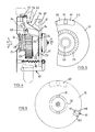
- This mechanism 7 comprises a timer 9 (see FIG. 2) consisting of a disc 10 driven in rotation by an electric motor 11 thanks to a gear 12.
- This gear 12 comprises a worm 13 driven in rotation by the engine 11 by l 'gear wheel 14,15,16,17.
- the motor 11 rotates a shaft 18 on which is mounted the toothed wheel 14.
- This toothed wheel 14 meshes with the toothed wheel 15 which is wedged on a shaft 19 parallel to the shaft 18 of rotation of the motor 11.
- This shaft 19 also carries the toothed wheel 16 whose teeth mesh with those of the wheel 17 wedged on a shaft 20, so as to rotate the worm 13 which is mounted on this same shaft 20.
- This set of toothed wheels 14, 15, 16, 17 makes it possible to reduce the speed of rotation of the electric motor 11.
- the worm 13 meshes with a ring gear 21 secured to the disc 10 (see Figures 3 and 4).
- This toothed ring 21 is coaxial with the disc 10 and carries a circular series of projections 22 engaged in a removable manner in recesses 23 formed in the disc 10, so as to secure the ring 21 of the disc 10.
- the shape of the projections 22 which follows of the recesses 23 has a face 24 inclined relative to the disc 10 and a face 25 substantially perpendicular to the disc 10.
- the protrusions 22 of the crown 21 are applied in the recesses 23 of the disc 10 thanks to the action of a spring 26 bearing, by means of a washer 28, on a face 27 of the housing 8 adjacent to the tank 1.
- the timer 9 includes an adjustment button 29 (see FIGS. 1 and 3) making it possible to rotate the disc 10 relative to the crown 21.
- This button 29 can be secured to the disc by the interlocking of two appendages 30 of the button 29 in cavities 31 that has a ring 32 integral with the disc 10 (see Figures 3 and 6).
- This button 29 advantageously bears on its face directed towards the outside of the housing 8 indications 33 of the cooking time, as well as an arrow 34 indicating the direction in which the user must rotate said button 29 (see FIG. 1).
- This button 29 thus makes it possible to adjust step by step the duration or time of cooking.
- the disc 10 is mounted on a hollow cylinder 35 fixed to the wall 27 of the housing 8 by means of a screw 36 and nuts 37 bearing respectively on the wall 27 and on a washer 38 placed at one end 39 of the cylinder 35 (see Figure 3).
- the disc 10 advantageously carries a nozzle 40 which follows the shape of the cylinder 35. On this nozzle 40 is mounted, in a movable manner, the crown 21.
- the latter has an annular bead 41 conforming to the cylindrical external shape of the nozzle 40 of the disc 10 and a circular groove 42 in which one end 43 of the spring 26 is housed.
- the slider 5 (see FIGS. 7 to 9) can move in a passage 44 formed in a room 45 which fits into a notch 46 (see FIG. 1) provided in the upper edge of the tank 1. It is obvious that at instead of such a notch 46, it is possible to provide a groove extending in the edge of the cover or both in the edge of the tank and of the cover.
- This slide 5 consists of two plates 47 secured to each other by means of bars 48. One of these bars 48 also serves as a pivot for the handle 3.
- the plates 47 have, in the vicinity of their end 49 adjacent to the basket 2, a notch 50 open towards the upper part of the plates and, near their end 51 adjacent to the handle 3, a part 52 offset from the lower part of the plates.
- the handle 3 is provided with a pusher 53 sliding on the face 54 of the handle opposite to that (55) adjacent to the basket 2 (see Figures 1 and 9).
- This pusher 53 is integral with a stop 56 which can project into a recess 57 formed in the handle 3.
- the handle 3 has at its end 58 adjacent to the hollow 57 a boss 59 which, when the handle 3 is substantially perpendicular to the part 45, bears at its end 58 on said part 45 (see FIG. 1).
- the disc 10 carries two cams 60, 61 mounted on the opposite faces of the disc 10 and in the vicinity of its periphery (see FIGS. 2 to 6). These cams act respectively on members 62, 63.
- the member 62 is intended to cause the displacement of the slide 5, so as to lift the basket 2 after a determined time interval.
- the member 63 it is intended to move the handle 3 away from a position in which it extends along the tank 1 (see FIGS. 8 and 9).
- the member 62 causing the displacement of the slide 5 comprises a bent rod 64 which can pivot (arrow W, axis A-A) relative to the tank 1 (see FIG. 2).
- This bent rod 64 consists of a bar formed by two sections 65,66 coaxial with its pivot axis AA, this bar having, between these two coaxial sections 65,66, a section 67 distant from the pivot axis AA and , at one end 68 of the section 66, a branch 69 substantially perpendicular to the axis AA.
- the remote section 67 is directed towards the disc 10, while the branch 69 is directed towards the slide 5.
- the bent rod 64 is fixed to the wall of the housing 8 by means of a perforated ear 70 and holes 71 drilled in the internal 72 and external 73 walls of the housing 8.
- a link 74 is articulated, on the one hand, to the section 67 and, on the other hand, to a return means 75 for this link 74 in its initial position, that is to say in a position in which it is not in contact with the cam 60.
- the return means 75 consists of a flexible folded blade 76, one end of which 77 is integral with the housing 8.
- this cam 60 When the cam 60 comes into contact with the rod 74, this cam 60 causes the displacement of the said rod 74 and the pivoting of the branch 69 of the member 62.
- This branch 69 is supported, during its pivoting, on a stop constituted by the pivot 48 of the handle 3, so as to move this slide 5 ( Figures 7 and 8, arrow Q) to lift the basket 2.
- the member 63 intended to move the handle 3 away from the position in which it extends along the tank 1 comprises an angled rod 78 which can pivot (arrow V, axis BB) relative to the tank 1.
- This rod 78 is consisting of a bar formed of two coaxial sections 79,80, this bar having a section 81 distant from the pivot axis (BB) between the two coaxial sections 79,80, a branch 82 substantially perpendicular to the pivot axis (BB) at one end 83 of one (79) of the coaxial sections 79,80 and a branch 84 provided with an arm 85 at the end of the other coaxial section 80.
- the branch 82 is directed towards the disc 10
- the branch 84 provided with the arm 85 is directed towards the tank 1.
- the member 63 is fixed to the wall of the housing 8 by means of a perforated ear 70 and holes 71 drilled in the internal 72 and external 73 walls of the housing 8.
- the section 81 remote from the pivot axis BB is subjected to the action of a return means constituted, for example, by a spring 86 secured to a wall of the housing 8.
- This spring 86 allows the member to be brought back 63 in its initial position, that is to say in a position in which the branch 84 or the arm 85 are not respectively in contact with the cam 61 and the handle 3.
- This displacement of the handle 3 makes it possible to open a switch 87 housed in the housing 8 and mounted in an electrical circuit 88 intended to allow the supply of current to the motor 11.
- the opening of the circuit 88 allows the engine 11 to stop .
- the members 62,63 advantageously have flanges 89 on their coaxial sections 65,66 79,80 intended to limit the movements of the members 62,63 in the direction of the arrows U.
- the cams 60 and 61 are advantageously mounted on the opposite faces of the disc 10, in the vicinity of its periphery. They have a first ramp 90 progressively rising from the disc 10 to a plate 91 and then a second ramp 92 progressively lowering towards the disc 10.
- the cams 60, 61 are arranged on the disc 10 so that, when the cam 60 has acted on the member 62 causing the displacement of the slide 5 so as to raise the basket 2, the second cam 61 acts on the member 63 to move the handle 3.
- This movement of the handle 3 causes the opening of the switch 87 and thus the stopping of the motor 11.
- This movement is facilitated by the presence, on the face 55 of the handle 3, of a protuberance 93 on which the arm 85 rests to move away the handle 3 of the position in which it extends along the tank 1.
- the handle 3 also has, on its face 95 adjacent to the housing 8, a groove or groove 94 in which can accommodate the branch 84 of the member 63 (see Figure 1).
- FIGs 7 to 9 show different positions that the handle 3 and the basket 2 can take when the basket 2 is in the tank 1.
- the basket 2 is suspended from the slide 5 by the device 6.
- This device consists of two lever arms 96, 97 articulated at one end 98 to an extension 99 of the part 45 and at the other end 100 to a plate 101 secured of the basket 2.
- the upper lever arm 96 has, at its end 98 hinged to the extension 99, a part 102 substantially perpendicular to the arm 96, this part 102 carrying a rod 103 engaged in the notches 50 of the plates 47 forming the slide 5.
- this cam 60 When the cam 60 comes into contact with the rod 74, this cam 60 causes the member 62 to pivot in the direction of the arrow W (see FIGS. 7 and 8), so as to move the slide 5 in the direction of the arrow Q.
- the movement of the slide 5 allows the rod 103 to be moved in the direction of arrow Q, so that the lever arms 96, 97 pivot around their articulation adjacent to their end 98 (arrow R), so as to lift the basket 2 5 in the direction of the arrow S.
- the handle 3 of the device according to the invention is advantageously embedded in a housing 104 formed between the housing 8 and a projecting part 105 of the device (see FIG. 1).
- this handle 3 When this handle 3 is engaged in this housing 104, it actuates the switch 87, so as to close the circuit 88 to allow the starting of the motor 11.
- the fitting of the handle 3 in the housing 104 can only be carried out when the arm 85 no longer bears on the protuberance 93 of the handle 3, that is to say when the cam 61 is no longer in contact with the member 63 or even when the cooking time has been adjusted by the rotation of the button 29 of the timer 9.
- FIG 10 is a partial perspective view of a cooking appliance according to the invention provided with a bell 105.
- This bell 105 has the shape of a bell 106 having a bottom 107 secured to a rod 108 of a arm 109 fixed to the cooking appliance or to the housing 8.
- the switch 87 comprises a control member consisting of a spring leaf 110, one end of which is integral with said switch 87.
- This blade 110 can bending in the direction of the arrow M under the action of the handle 3, when the latter extends substantially along the tank 1.
- the blade 110 has an appendage forming a hammer 111 situated at the end 112 of the blade opposite the integral end of the switch 87.
- the handle 3 is no longer supported on said blade 110, so that the hammer 111 of this blade 110 hits the bell 105, so as to warn the user by an audible signal that the basket 2 is in the raised position.
- the electric cooking appliance according to the invention can be provided with various indicators, such as indicator lights indicating that the appliance is switched on and that the mechanism 7 may include several discs 10 to allow food to be cooked in several stages.
- the device according to the invention allows the user to see if the basket 2 is removed from the cooking body contained in the tank 1, by moving the handle 3 away from its position in which it extends along of the tank 1, that is to say thanks to the disengagement of the handle 3 from its housing 104.
- the device according to the invention has a double cooking security since the lowering of the basket 2 can only take place when the handle 3 is engaged in the housing 104 and when the timer 9 is set.
- the cooking appliance according to the invention has the advantage of being able to be used manually or with the timer according to the choice of the user.
- FIGs 11 and 12 are views similar to Figures 3 and 2 of a portion of a cooking appliance according to the invention.
- This device comprises a timer 9 consisting of a disc 10 driven in rotation by a motor 11.
- the disc 10 carries a cam 60 acting on a member 62 causing the displacement of a slide, at one end of which hangs a basket.
- the movement of the slide makes it possible to lift said basket in the tank of the cooking appliance, this movement taking place after an interval of time determined by the timer 9.
- the motor 11 is mounted in a circuit 88 which includes a system 87 allowing the rotation of the disc 10 to be stopped when the basket is in its raised position.
- the system 87 which allows the rotation of the disc 10 to stop includes: a first element 113 driven in rotation by the toothed wheel 14 mounted on the shaft 18 of the motor 11 and a second element 114 intended to rotate the disk 10.
- This intermediate piece 115 is advantageously a cam located on the face of the disc 10 carrying the cam 60.
- the elements 113,114 consist of two toothed wheels mounted on the same shaft 116, at least one (114) of said wheels being able to slide along said shaft 116.
- the toothed wheel 113 has a face 117 which can be associated with a face 118 of the wheel 114.
- the faces 117, 118 are provided with a series of teeth 119, the teeth of the face 117 of the wheel 113 matching the shape of the teeth of the face 118.
- the wheel 114 is provided, in the vicinity of its ends 120, 121, with a flange 122, 123. These flanges 122, 123 ensure permanent contact between the wheel 114 and a peripheral edge of the disc 10.
- the flange 123 located near the end 121 of the wheel 114 has a groove 125 in which one end 126 of a member 63 is engaged. This member 63 is intended to move the handle 3 away from the position in which it extends along the tank.
- This member 63 comprises a bent rod 78 which can pivot (arrow V, axis BB) relative to the tank 1.
- This bent rod 78 consists of a bar formed of a section 127 coaxial with the axis BB provided each with its ends 128,129 of a branch 130,131.
- the branch 130 is partially engaged in the groove 125 of the flange 123, while the branch 131 is intended to act on the handle 3 so as to move it away.
- the branches 130, 131 are substantially perpendicular to the pivot axis B-B.
- the branch 131 carries an arm 85 intended to act on the handle 3.
- the cam 115 preferably has a ramp 124, the latter rising progressively from the disc 10.
- the motor 11 continuously drives the wheel 113, so that the latter can drive a wheel (not shown) intended to measure the time of use of the cooking appliance.
- This wheel may bear indications intended, for example, to warn the user that he must replace the fatty matter contained in the tank 1 of the appliance. Such an indication is important, since it is well known that all fats or oils, used in cooking appliances such as fryers, have a determined life time. When this life time is exceeded, the fat or oil becomes unfit for consumption.
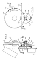
- Figures 13 to 16 are views of another embodiment of a cooking appliance according to the invention.
- This embodiment differs from that shown in FIGS. 11 and 12 by the fact that the wheel 113 can slide along the shaft 116, while the wheel 114 is fixed on this shaft 116.
- These wheels 113, 114 have on one of their lateral faces 117, 118 teeth 119.
- the motor 11 drives the rotation of the disc 10 .
- the wheel 114 has at one of its ends a flange 123, while the wheel 113 has a groove 133 in which is engaged one end 134 of a bar 135 acting on the handle 3 so as to move it away from its position in which it extends along the tank.
- This bar 135 is articulated to a wall 136 of the device, so that the movement of the wheel 113 in the direction of the arrow Y causes the pivoting of said bar 135 relative to its articulation, this pivoting (arrow C) causing the distance from the handle 3 of the tank (see Figures 15 and 16, Figure 15 being a view along line XV-XV of the apparatus shown in Figure 13).
- the wheel 113 can be moved away from the wheel 114 by means of a cam 137 situated on the disc 10.
- This cam 137 when it bears on the wheel 113, causes the latter to slide (arrow Y) along the shaft 116.
- the distance of the wheel 113 by relative to the wheel 114 makes it possible to stop the rotation of the wheel 114 and therefore of the disc 10.
- the wheel 113 which is still driven by the motor 11 meshes with a wheel intended to measure the time of use of the device or the time of use of the fat or oil placed in the tank of the device (not shown).
- the bar 135 is connected to one (138) of its ends a spring 139 fixed to the wall 136 of the device. This spring 139 keeps the bar 135 either in a position where it moves the wheel 113 away from the wheel 114, or in a position where it keeps the wheel 113 and the wheel 114 in contact.
- This bar 135 is advantageously provided with a hammer intended to strike a bell when the basket is in the raised position.
Landscapes
- Engineering & Computer Science (AREA)
- Food Science & Technology (AREA)
- Frying-Pans Or Fryers (AREA)
- Food-Manufacturing Devices (AREA)
- Cookers (AREA)
Applications Claiming Priority (2)
| Application Number | Priority Date | Filing Date | Title |
|---|---|---|---|
| BE8701082A BE1000919A3 (fr) | 1987-09-24 | 1987-09-24 | Appareil de cuisson electrique. |
| BE8701082 | 1987-09-24 |
Publications (2)
| Publication Number | Publication Date |
|---|---|
| EP0309435A1 true EP0309435A1 (de) | 1989-03-29 |
| EP0309435B1 EP0309435B1 (de) | 1992-12-09 |
Family
ID=3882879
Family Applications (1)
| Application Number | Title | Priority Date | Filing Date |
|---|---|---|---|
| EP19880870153 Expired - Lifetime EP0309435B1 (de) | 1987-09-24 | 1988-09-23 | Elektrisches Kochgerät |
Country Status (3)
| Country | Link |
|---|---|
| EP (1) | EP0309435B1 (de) |
| BE (1) | BE1000919A3 (de) |
| DE (1) | DE3876568T2 (de) |
Cited By (3)
| Publication number | Priority date | Publication date | Assignee | Title |
|---|---|---|---|---|
| FR2662927A1 (fr) * | 1990-06-12 | 1991-12-13 | Moulinex Sa | Friteuse electrique. |
| CN102239895A (zh) * | 2011-04-28 | 2011-11-16 | 周林斌 | 油炸锅的滚筒笼 |
| CN116602572A (zh) * | 2023-06-12 | 2023-08-18 | 东莞市优创智能机械有限公司 | 一种取放方形餐盒的驱动装置 |
Citations (9)
| Publication number | Priority date | Publication date | Assignee | Title |
|---|---|---|---|---|
| US1529342A (en) * | 1923-05-14 | 1925-03-10 | Christy Sam | Automatic electric toaster |
| US2165204A (en) * | 1937-10-20 | 1939-07-11 | Lynwood E Storey | Automatic bread toasting apparatus |
| US2253752A (en) * | 1939-07-24 | 1941-08-26 | Kenneth E Bemis | Timing device |
| US2578971A (en) * | 1951-02-16 | 1951-12-18 | Leo F Eberle | Automatic electric bread toaster |
| US2724322A (en) * | 1951-07-20 | 1955-11-22 | Westinghouse Electric Corp | Toasting apparatus |
| US2878748A (en) * | 1955-11-07 | 1959-03-24 | Toastwell Company Inc | Bread toaster |
| US2915000A (en) * | 1954-01-28 | 1959-12-01 | Wayne D Hetzel | Pop-up cooker |
| US3430553A (en) * | 1968-02-16 | 1969-03-04 | Carmelo V Di Pietro | Deep fat fryer |
| EP0149856A1 (de) * | 1984-01-21 | 1985-07-31 | Nova Electro International N.V. | Elektrisches Fritiergerät mit Drahtkorb und Handgriff |
-
1987
- 1987-09-24 BE BE8701082A patent/BE1000919A3/fr not_active IP Right Cessation
-
1988
- 1988-09-23 EP EP19880870153 patent/EP0309435B1/de not_active Expired - Lifetime
- 1988-09-23 DE DE19883876568 patent/DE3876568T2/de not_active Expired - Fee Related
Patent Citations (9)
| Publication number | Priority date | Publication date | Assignee | Title |
|---|---|---|---|---|
| US1529342A (en) * | 1923-05-14 | 1925-03-10 | Christy Sam | Automatic electric toaster |
| US2165204A (en) * | 1937-10-20 | 1939-07-11 | Lynwood E Storey | Automatic bread toasting apparatus |
| US2253752A (en) * | 1939-07-24 | 1941-08-26 | Kenneth E Bemis | Timing device |
| US2578971A (en) * | 1951-02-16 | 1951-12-18 | Leo F Eberle | Automatic electric bread toaster |
| US2724322A (en) * | 1951-07-20 | 1955-11-22 | Westinghouse Electric Corp | Toasting apparatus |
| US2915000A (en) * | 1954-01-28 | 1959-12-01 | Wayne D Hetzel | Pop-up cooker |
| US2878748A (en) * | 1955-11-07 | 1959-03-24 | Toastwell Company Inc | Bread toaster |
| US3430553A (en) * | 1968-02-16 | 1969-03-04 | Carmelo V Di Pietro | Deep fat fryer |
| EP0149856A1 (de) * | 1984-01-21 | 1985-07-31 | Nova Electro International N.V. | Elektrisches Fritiergerät mit Drahtkorb und Handgriff |
Cited By (6)
| Publication number | Priority date | Publication date | Assignee | Title |
|---|---|---|---|---|
| FR2662927A1 (fr) * | 1990-06-12 | 1991-12-13 | Moulinex Sa | Friteuse electrique. |
| EP0467065A1 (de) * | 1990-06-12 | 1992-01-22 | Moulinex | Elektrisches Fritiergerät |
| US5165329A (en) * | 1990-06-12 | 1992-11-24 | Moulinex (Societe Anonyme) | Electric deep fat fryer |
| CN102239895A (zh) * | 2011-04-28 | 2011-11-16 | 周林斌 | 油炸锅的滚筒笼 |
| CN102239895B (zh) * | 2011-04-28 | 2014-04-23 | 周林斌 | 油炸锅的滚筒笼 |
| CN116602572A (zh) * | 2023-06-12 | 2023-08-18 | 东莞市优创智能机械有限公司 | 一种取放方形餐盒的驱动装置 |
Also Published As
| Publication number | Publication date |
|---|---|
| DE3876568T2 (de) | 1993-04-08 |
| BE1000919A3 (fr) | 1989-05-16 |
| EP0309435B1 (de) | 1992-12-09 |
| DE3876568D1 (de) | 1993-01-21 |
Similar Documents
| Publication | Publication Date | Title |
|---|---|---|
| EP1130990B1 (de) | BEFESTIGUNGSMECHANISMUS ZUM FIXIEREN EINES DECKELS MIT EINGEBAUTEM MOTOR EINER KüCHENMASCHINE AUF EINER SCHüSSEL | |
| EP0162482B1 (de) | Fritierkorb mit Handgriff | |
| FR2810642A1 (fr) | Dispositif de verrouillage de couvercle | |
| EP1525833B1 (de) | Brotroster | |
| EP1075203A1 (de) | Fritiergerät mit filteranlage für den haushalt | |
| FR2588097A1 (fr) | Appareil nettoyeur et sterilisateur des lentilles de contact | |
| EP0309435B1 (de) | Elektrisches Kochgerät | |
| EP4014808B1 (de) | Elektrisches kochgerät für das kochen von lebensmittelprodukten | |
| EP1493370B1 (de) | Haushaltsgerät zum Bereiten von Nahrungsmitteln mit einem verbesserten Griff | |
| EP1161168B1 (de) | Elektrisches gerät des typs waffeleisen mit automatischer öffnung | |
| FR2530136A1 (fr) | Dispositif de commande pour lave-vaisselle | |
| FR2575394A1 (fr) | Personnage-jouet anime | |
| FR2868677A1 (fr) | Appareil electrique de chauffage de liquide | |
| EP0074911B1 (de) | Maschine zum Extrudieren von Teigwaren | |
| FR3111061A1 (fr) | Appareil culinaire avec dispositif d’entrainement a corde a commande amovible | |
| EP1604597B1 (de) | Brotroster | |
| FR2668354A1 (fr) | Tournebroche a mouvements composes de giration et de rotation. | |
| EP1566128B1 (de) | Haushaltsgerät aus scharnierartig verbundenen Rostelementen | |
| FR2464046A1 (fr) | Grille-pain electrique a declenchement automatique perfectionne | |
| FR2642010A1 (fr) | Decoration mobile | |
| FR2808467A1 (fr) | Appareil electrique de traitement d'aliments comportant un organe presseur | |
| FR2769198A1 (fr) | Appareil electromenager de preparation culinaire, du genre robot menager, comportant un dispositif de deverrouillage simplifie | |
| FR2682583A1 (fr) | Tourne-brochettes automatique. | |
| FR2495353A1 (fr) | Dispositif de commande de programmateur | |
| FR2611491A1 (fr) | Appareil destine a nourrir les handicapes |
Legal Events
| Date | Code | Title | Description |
|---|---|---|---|
| PUAI | Public reference made under article 153(3) epc to a published international application that has entered the european phase |
Free format text: ORIGINAL CODE: 0009012 |
|
| AK | Designated contracting states |
Kind code of ref document: A1 Designated state(s): BE CH DE ES FR GB IT LI NL |
|
| 17P | Request for examination filed |
Effective date: 19890918 |
|
| 17Q | First examination report despatched |
Effective date: 19910430 |
|
| RAP1 | Party data changed (applicant data changed or rights of an application transferred) |
Owner name: NOVA ELECTRO INTERNATIONAL N.V. |
|
| GRAA | (expected) grant |
Free format text: ORIGINAL CODE: 0009210 |
|
| AK | Designated contracting states |
Kind code of ref document: B1 Designated state(s): BE CH DE ES FR GB IT LI NL |
|
| PG25 | Lapsed in a contracting state [announced via postgrant information from national office to epo] |
Ref country code: NL Effective date: 19921209 Ref country code: GB Effective date: 19921209 Ref country code: ES Free format text: THE PATENT HAS BEEN ANNULLED BY A DECISION OF A NATIONAL AUTHORITY Effective date: 19921209 |
|
| REF | Corresponds to: |
Ref document number: 3876568 Country of ref document: DE Date of ref document: 19930121 |
|
| ITF | It: translation for a ep patent filed | ||
| NLV1 | Nl: lapsed or annulled due to failure to fulfill the requirements of art. 29p and 29m of the patents act | ||
| GBV | Gb: ep patent (uk) treated as always having been void in accordance with gb section 77(7)/1977 [no translation filed] |
Effective date: 19921209 |
|
| PGFP | Annual fee paid to national office [announced via postgrant information from national office to epo] |
Ref country code: FR Payment date: 19930721 Year of fee payment: 6 |
|
| PGFP | Annual fee paid to national office [announced via postgrant information from national office to epo] |
Ref country code: BE Payment date: 19930723 Year of fee payment: 6 |
|
| PG25 | Lapsed in a contracting state [announced via postgrant information from national office to epo] |
Ref country code: LI Effective date: 19930930 Ref country code: CH Effective date: 19930930 |
|
| PLBE | No opposition filed within time limit |
Free format text: ORIGINAL CODE: 0009261 |
|
| STAA | Information on the status of an ep patent application or granted ep patent |
Free format text: STATUS: NO OPPOSITION FILED WITHIN TIME LIMIT |
|
| PGFP | Annual fee paid to national office [announced via postgrant information from national office to epo] |
Ref country code: DE Payment date: 19931119 Year of fee payment: 6 |
|
| 26N | No opposition filed | ||
| REG | Reference to a national code |
Ref country code: CH Ref legal event code: PL |
|
| PG25 | Lapsed in a contracting state [announced via postgrant information from national office to epo] |
Ref country code: BE Effective date: 19940930 |
|
| BERE | Be: lapsed |
Owner name: NOVA ELECTRO INTERNATIONAL N.V. Effective date: 19940930 |
|
| PG25 | Lapsed in a contracting state [announced via postgrant information from national office to epo] |
Ref country code: FR Effective date: 19950531 |
|
| PG25 | Lapsed in a contracting state [announced via postgrant information from national office to epo] |
Ref country code: DE Effective date: 19950601 |
|
| REG | Reference to a national code |
Ref country code: FR Ref legal event code: ST |
|
| PG25 | Lapsed in a contracting state [announced via postgrant information from national office to epo] |
Ref country code: IT Free format text: LAPSE BECAUSE OF NON-PAYMENT OF DUE FEES;WARNING: LAPSES OF ITALIAN PATENTS WITH EFFECTIVE DATE BEFORE 2007 MAY HAVE OCCURRED AT ANY TIME BEFORE 2007. THE CORRECT EFFECTIVE DATE MAY BE DIFFERENT FROM THE ONE RECORDED. Effective date: 20050923 |