EP0308935B1 - Armbandantenne für Radioempfänger, der in eine Uhr eingebaut ist - Google Patents
Armbandantenne für Radioempfänger, der in eine Uhr eingebaut ist Download PDFInfo
- Publication number
- EP0308935B1 EP0308935B1 EP88115606A EP88115606A EP0308935B1 EP 0308935 B1 EP0308935 B1 EP 0308935B1 EP 88115606 A EP88115606 A EP 88115606A EP 88115606 A EP88115606 A EP 88115606A EP 0308935 B1 EP0308935 B1 EP 0308935B1
- Authority
- EP
- European Patent Office
- Prior art keywords
- watchstrap
- antenna
- bracelet
- watchcase
- antenna according
- Prior art date
- Legal status (The legal status is an assumption and is not a legal conclusion. Google has not performed a legal analysis and makes no representation as to the accuracy of the status listed.)
- Expired - Lifetime
Links
- 239000004020 conductor Substances 0.000 claims description 31
- 239000002184 metal Substances 0.000 claims description 17
- 239000011248 coating agent Substances 0.000 claims description 2
- 238000000576 coating method Methods 0.000 claims description 2
- 238000000465 moulding Methods 0.000 claims description 2
- 210000000707 wrist Anatomy 0.000 description 11
- 230000006978 adaptation Effects 0.000 description 4
- 239000003990 capacitor Substances 0.000 description 2
- 238000010276 construction Methods 0.000 description 2
- 230000001939 inductive effect Effects 0.000 description 2
- 230000005855 radiation Effects 0.000 description 2
- 208000031968 Cadaver Diseases 0.000 description 1
- 206010013786 Dry skin Diseases 0.000 description 1
- 241000897276 Termes Species 0.000 description 1
- 230000002745 absorbent Effects 0.000 description 1
- 239000002250 absorbent Substances 0.000 description 1
- 239000002253 acid Substances 0.000 description 1
- 238000005452 bending Methods 0.000 description 1
- 239000000470 constituent Substances 0.000 description 1
- 230000001419 dependent effect Effects 0.000 description 1
- 238000010586 diagram Methods 0.000 description 1
- 230000037336 dry skin Effects 0.000 description 1
- 230000000694 effects Effects 0.000 description 1
- 235000021183 entrée Nutrition 0.000 description 1
- 239000004744 fabric Substances 0.000 description 1
- 239000012212 insulator Substances 0.000 description 1
- 230000010354 integration Effects 0.000 description 1
- 238000005259 measurement Methods 0.000 description 1
- 230000004060 metabolic process Effects 0.000 description 1
- 230000010287 polarization Effects 0.000 description 1
- 229920003223 poly(pyromellitimide-1,4-diphenyl ether) Polymers 0.000 description 1
- 239000011347 resin Substances 0.000 description 1
- 229920005989 resin Polymers 0.000 description 1
- 230000035900 sweating Effects 0.000 description 1
- 210000001519 tissue Anatomy 0.000 description 1
- 230000005068 transpiration Effects 0.000 description 1
- 238000004804 winding Methods 0.000 description 1
Images

Classifications
-
- G—PHYSICS
- G04—HOROLOGY
- G04G—ELECTRONIC TIME-PIECES
- G04G21/00—Input or output devices integrated in time-pieces
- G04G21/04—Input or output devices integrated in time-pieces using radio waves
-
- G—PHYSICS
- G04—HOROLOGY
- G04R—RADIO-CONTROLLED TIME-PIECES
- G04R60/00—Constructional details
- G04R60/04—Antennas attached to or integrated in watch bracelets
-
- H—ELECTRICITY
- H01—ELECTRIC ELEMENTS
- H01Q—ANTENNAS, i.e. RADIO AERIALS
- H01Q1/00—Details of, or arrangements associated with, antennas
- H01Q1/27—Adaptation for use in or on movable bodies
- H01Q1/273—Adaptation for carrying or wearing by persons or animals
Definitions
- the present invention relates to a wristband antenna for radio receiver integrated in a watch.
- the real behavior of the arm is difficult to quantify and can be different depending on the morphology of the individual, his metabolism and the way of wearing his watch loose or tight.
- the antenna is optimized, in terms of its effectiveness, to be worn, it must remain operational when the watch strap is removed to be placed on a table, for example.
- the antenna design must therefore take account of these two operating modes. Another problem, linked to the necessary miniaturization, is to avoid the antenna adaptation circuits comprising inductors which are bulky and cause losses on the signal.
- the antenna of the present invention includes in its structure the inductance necessary for its own agreement.
- the invention proposes a wristband antenna for radio receiver integrated in a watch, said watch being formed of a case and a bracelet, this case containing said receiver and a first metal part forming the mass of the receiver and which is located near the bottom of said case, said antenna being a two-strand dipole antenna arranged inside the bracelet;
- the first strand connected to the input of said receiver, being formed of a first metallic conductor disposed inside the strap near the external surface of the strap on the top side of the watch case, and having the shape of a wire, winding between the two side walls of the bracelet, of unfolded length close to ⁇ / 4, ⁇ being the wavelength corresponding to the central frequency of the signal to be received;
- the second strand being formed of a second metallic conductor disposed inside the bracelet close to the internal surface of the bracelet on the bottom side of the watch case, and connected to the first metal part.
- Such a wristband antenna makes it possible to obtain a large bandwidth on reception, a great simplicity of embodiment in particular requiring no adaptation circuit for a receiver of input impedance close to 50 ⁇ .
- the second metallic conductor like the first conductor, in the form of a sinuating wire between the two side walls of the bracelet, the unfolded length of this conductor being ⁇ / 4, ⁇ being the corresponding wavelength at the center frequency to be received.
- Figures 1 and 2 show a watch 10 consisting of a housing 11 and a bracelet, for example formed of two parts 12 and 13.
- a receiver 14 is disposed in the housing 11.
- the inventive bracelet antenna comprises at least a first metallic conductor 16 disposed near the external surface 17 of the strap 12, on the top side 18 of the case 11.
- This first conductor 16 is connected to the input of the receiver 14. It has the shape of a sinuous wire between the two side walls 20 and 21 of the strap 12. We will speak later of a "zigzag" structure. This wire has an extended length of the order of ⁇ / 4; ⁇ being the wavelength corresponding to the center frequency of the signal to be received.
- the bracelet antenna may also include a second conductor 22 connected to the ground of the receiver 14.
- This second conductor 22 may have the form of a film placed close to the internal surface 19 of the bracelet situated on the bottom side 23 of the housing 11 .
- each of the two conductors 16 and 22 is disposed respectively inside one of the two parts 12 and 13 of the bracelet.
- Figures 1 and 2 of the invention are only schematic figures. Thus, for greater clarity, the proximity of the first and second conductors respectively to the external face and the internal face of the bracelet, which does not appear clearly, given the thin thickness of the bracelet, in these two figures 1 and 2, is highlighted in Figures 3A and 3B.
- This bracelet antenna behaves like a two-strand antenna, or like a dipole integrated into the bracelet, of equivalent electrical length equal to ⁇ / 2.
- the unworn watch therefore reacts like a dipole.
- the bottom of the case, or the second strand 13 of the bracelet ensures the earthing of the receiver.
- the other strand 12 the dipole of which is raised a little less than the thickness of the bracelet, produces a capacitor capturing the radial field around the arm.
- the dipole is produced, at least in part, by the "zigzag" structure allowing integration of the tuning choke of the antenna in the strand itself.
- the second conductor 22 can also have a "zig-zag" structure as represented by the first connector. In this case, it also has an extended length of ⁇ / 4.
- the realization of a conductor in "zig-zag” is done by embedded wire or ribbon of a shape ensuring the bending, or by a printed circuit on flexible film sliding freely in a groove of the bracelet.
- the antenna can also be produced with conductors embedded in the molding, their shape ensuring the flexibility of the bracelet.
- the second conductor 22 connected to the bottom of the metal case is intended to provide, in addition to the case, the taking of the potential of the arm.
- the bottom 23 of the receiver watch case in fact, provides a galvanic or capacitive connection with the wearer by means of a large conductive surface covered or not by a thin insulating coating.
- the first conductor 16 performs a complex function depending on the degree of tightening of the bracelet and the degree of sweating of the wearer.
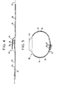
- a variant of the invention which increases its efficiency, consists in using, as shown in FIG. 4, the upper part 24 of the housing 11, in the form for example of a metal crown isolated from the bottom of the housing, to increase the average effective height of the wristband antenna.
- the efficiency of the antenna in radial behavior is increased with a sufficient length of the two conductors 16 and 22, as shown in FIG. 5, by the doubling of thickness 27 when the bracelet is buckled and the normal projection 25 made by the end of a part 12 of the bracelet after passing through the loop 26.
- a bracelet antenna produced on Kapton film according to the invention makes it possible to obtain an optimum gain located at - 15dB compared to the ⁇ / 2 dipole for the bracelet worn on the wrist.
- This gain is, of course, a function of the direction of measurement and of the multiple attitudes that the wearer of the bracet can adopt.
- the deployed and unworn bracelet gives a gain of -15dB also with ommidirectional radiation relative to the electrical axis of the antenna.
- the bracelet 12, 13 can be produced in a single piece, it can for example be an elastic bracelet.
- interconnection devices of the bracelet to the case, known to those skilled in the art, have not been described: this may be, for example, electrical contacts produced by means of bars, flexible connections by film soldered or crimped.
Landscapes
- Physics & Mathematics (AREA)
- General Physics & Mathematics (AREA)
- Support Of Aerials (AREA)
- Details Of Aerials (AREA)
- Electric Clocks (AREA)
- Structure Of Receivers (AREA)
Claims (9)
- Armbandantenne für einen in eine Uhr (10) eingebauten Radioempfänger, wobei die Uhr (10) aus einem Gehäuse (11) und einem Armband (12, 13) besteht und das Gehäuse (12) den Empfänger (14) und ein erstes Metallteil (15) als Masse des Empfängers in der Nähe des Bodens (23) des Gehäuses (11) enthält, wobei die Antenne eine aus zwei Leitern bestehende, im Inneren des Armbands untergebrachte Dipolantenne ist, wobei der erste, mit dem Eingang des Empfängers (14) verbundene Leiter aus einem ersten metallischen Leiter (16) besteht, der im Inneren des Armbands (12, 13) in der Nähe der äußeren Oberfläche (17) des Armbands (12, 13) an der Oberseite (18) des Gehäuses (11) der Uhr (10) angeordnet ist und die Form eines schlangenförmig zwischen den beiden Seitenwänden (20, 21) des Armbands (12, 13) verlaufenden Drahts mit einer gestreckten Länge in der Nähe von λ/4 besitzt, wobei λ die der Mittenfrequenz des zu empfangenden Signals entsprechende Wellenlänge ist, während der zweite Leiter aus einem zweiten metallischen Leiter (22) besteht, der im Inneren des Armbands in der Nähe der inneren Oberfläche des Armbands (12, 13) an der Bodenseite des Gehäuses (11) der Uhr (10) angeordnet und mit dem ersten Metallteil (15) verbunden ist.
- Armbandantenne nach Anspruch 1, dadurch gekennzeichnet, daß der zweite metallische Leiter (22) die Form eines Films besitzt.
- Armbandantenne nach Anspruch 1, dadurch gekennzeichnet, daß der zweite metallische Leiter (22) die Form eines schlangenförmig zwischen den beiden Seitenwänden (20, 21) des Armbands (12, 13) verlaufenden Drahts besitzt, wobei die gestreckte Länge dieses zweiten metallischen Leiters (16) in der Nähe von λ/4 liegt und λ die der Mittenfrequenz des zu empfangenden Signals entsprechende Wellenlänge ist.
- Armbandantenne nach Anspruch 3, dadurch gekennzeichnet, daß das Armband (12, 13) zwei Teile (12, 13) aufweist und die beiden Leiter (16, 22) jeweils im Inneren eines der beiden Teile (12, 13) angeordnet sind.
- Armbandantenne nach einem beliebigen der vorhergehenden Ansprüche, dadurch gekennzeichnet, daß der Boden (23) des Gehäuses (11) der Empfängeruhr (10) eine galvanische oder kapazitive Verbindung mit dem Träger der Uhr aufgrund einer großen leitenden Oberfläche bewirkt, die ggfs. mit einem Isolierüberzug geringer Dicke bedeckt ist.
- Armbandantenne nach einem beliebigen der vorhergehenden Ansprüche, dadurch gekennzeichnet, daß sie aus einer gedruckten Schaltung auf einem elastischen Film besteht.
- Armbandantenne nach einem beliebigen der Ansprüche 1 bis 5, dadurch gekennzeichnet, daß sie unter Verwendung eines beim Gießen eingebetteten Leiters hergestellt ist und eine die Elastizität des Armbands gewährleistende Form besitzt.
- Armbandantenne nach einem beliebigen der vorhergehenden Ansprüche, dadurch gekennzeichnet, daß der erste metallische Leiter (16) mit einem zweiten Metallteil (24) verbunden ist, das im oberen Abschnitt des Gehäuses (11) angeordnet und gegen das erste Metallteil (15) am Boden (23) des Gehäuses (11) isoliert ist.
- Armbandantenne nach Anspruch 8, dadurch gekennzeichnet, daß das zweite Metallteil (24) die Form einer Kurve besitzt.
Applications Claiming Priority (2)
| Application Number | Priority Date | Filing Date | Title |
|---|---|---|---|
| FR8713265A FR2621178B1 (fr) | 1987-09-25 | 1987-09-25 | Antenne bracelet pour recepteur radioelectrique integre dans une montre |
| FR8713265 | 1987-09-25 |
Publications (2)
| Publication Number | Publication Date |
|---|---|
| EP0308935A1 EP0308935A1 (de) | 1989-03-29 |
| EP0308935B1 true EP0308935B1 (de) | 1992-02-19 |
Family
ID=9355217
Family Applications (1)
| Application Number | Title | Priority Date | Filing Date |
|---|---|---|---|
| EP88115606A Expired - Lifetime EP0308935B1 (de) | 1987-09-25 | 1988-09-22 | Armbandantenne für Radioempfänger, der in eine Uhr eingebaut ist |
Country Status (4)
| Country | Link |
|---|---|
| EP (1) | EP0308935B1 (de) |
| DE (1) | DE3868469D1 (de) |
| ES (1) | ES2029508T3 (de) |
| FR (1) | FR2621178B1 (de) |
Families Citing this family (14)
| Publication number | Priority date | Publication date | Assignee | Title |
|---|---|---|---|---|
| US5243356A (en) * | 1988-08-05 | 1993-09-07 | Seiko Epson Corporation | Antenna circuit and wrist radio instrument |
| IT1231784B (it) * | 1989-05-15 | 1992-01-14 | Telesia Spa | Dispositivo portatile personale di ricezione e presentazione di informazioni trasmesse via radio, integrato con orologio |
| JP3055703B2 (ja) * | 1990-02-20 | 2000-06-26 | 日本電信電話株式会社 | 腕時計形受信機 |
| JP2985296B2 (ja) * | 1990-05-16 | 1999-11-29 | セイコーエプソン株式会社 | 電子機器のアンテナ接続装置 |
| GB0127566D0 (en) * | 2001-11-19 | 2002-01-09 | Psion Digital Ltd | Antenna for a portable radio device |
| EP1513220B1 (de) | 2003-09-03 | 2018-10-31 | The Swatch Group Research and Development Ltd | Patch-Antenne integriert in einer Armbanduhr |
| GB2494922A (en) * | 2011-09-26 | 2013-03-27 | Antenova Ltd | External and flexible groundplane extensions for antennas |
| WO2014107158A1 (en) * | 2013-01-04 | 2014-07-10 | Evado Filip Holding Ltd. | Band with an antenna for use with a wireless electronic device |
| KR102025889B1 (ko) * | 2013-11-14 | 2019-09-26 | 주식회사 위츠 | 휴대 단말기와 무선 충전 장치 및 무선 충전 구조 |
| KR102300862B1 (ko) * | 2014-09-15 | 2021-09-13 | 삼성전자주식회사 | 전자 장치 |
| US9653786B2 (en) * | 2015-06-27 | 2017-05-16 | Intel Corporation | Wearable antenna system |
| CN106558758B (zh) * | 2016-11-28 | 2024-06-11 | 南昌黑鲨科技有限公司 | 可穿戴设备 |
| CN112165545A (zh) * | 2020-09-29 | 2021-01-01 | 维沃移动通信有限公司 | 穿戴式电子设备、天线控制方法和存储介质 |
| CN112216957B (zh) * | 2020-09-29 | 2023-12-01 | 维沃移动通信有限公司 | 穿戴电子设备、天线控制方法和存储介质 |
Citations (1)
| Publication number | Priority date | Publication date | Assignee | Title |
|---|---|---|---|---|
| EP0288676A2 (de) * | 1987-05-01 | 1988-11-02 | Timex Corporation | Elastisches Antennenband zur Anwendung in Armbanduhren |
Family Cites Families (4)
| Publication number | Priority date | Publication date | Assignee | Title |
|---|---|---|---|---|
| DE1019717B (de) * | 1956-01-03 | 1957-11-21 | Anton Kathrein Fabrik Elektrot | Verkuerzter Dipol |
| US3032651A (en) * | 1957-07-02 | 1962-05-01 | Gisiger-Stahli Josef | Wrist carried radio set |
| GB8313658D0 (en) * | 1983-05-17 | 1983-06-22 | Sinclair Res Ltd | Strap assembly |
| JPH073923B2 (ja) * | 1985-02-06 | 1995-01-18 | 公人 堀江 | バンド型アンテナ装置 |
-
1987
- 1987-09-25 FR FR8713265A patent/FR2621178B1/fr not_active Expired
-
1988
- 1988-09-22 EP EP88115606A patent/EP0308935B1/de not_active Expired - Lifetime
- 1988-09-22 DE DE8888115606T patent/DE3868469D1/de not_active Expired - Lifetime
- 1988-09-22 ES ES88115606T patent/ES2029508T3/es not_active Expired - Lifetime
Patent Citations (1)
| Publication number | Priority date | Publication date | Assignee | Title |
|---|---|---|---|---|
| EP0288676A2 (de) * | 1987-05-01 | 1988-11-02 | Timex Corporation | Elastisches Antennenband zur Anwendung in Armbanduhren |
Also Published As
| Publication number | Publication date |
|---|---|
| ES2029508T3 (es) | 1992-08-16 |
| EP0308935A1 (de) | 1989-03-29 |
| DE3868469D1 (de) | 1992-03-26 |
| FR2621178B1 (fr) | 1989-12-01 |
| FR2621178A1 (fr) | 1989-03-31 |
Similar Documents
| Publication | Publication Date | Title |
|---|---|---|
| EP0308935A1 (de) | Armbandantenne für Radioempfänger, der in eine Uhr eingebaut ist | |
| EP0924797B1 (de) | Multifrequenzstreifenleitungsantenne und Gerät mit einer derartigen Antenne | |
| EP0427654B1 (de) | Wendelförmige Resonanzantenne, bestehend aus je vier Wendelleitern übereinander | |
| EP1315234A1 (de) | VHF-Empfangsantenne integriert in das Armband einer tragbaren elektronischen Vorrichtung | |
| EP1145378B1 (de) | Zweiband-übertragungsanordnung und eine antenne für diese anordnung | |
| FR2860927A1 (fr) | Antenne interne de faible volume | |
| FR2825517A1 (fr) | Antenne a plaque | |
| EP2422403B1 (de) | Breitbandige mehrfachantenne mit geringem querschnitt | |
| FR2779276A1 (fr) | Dispositif de radiocommunication et antenne a fente en boucle | |
| CA2267536A1 (fr) | Dispositif de radiocommunication et antenne bifrequence realisee selon la technique des microrubans | |
| FR2535532A1 (fr) | Antenne interieure pour un recepteur de television | |
| EP0805507A1 (de) | Empfangs- und/oder Sendeeinrichtung für Funksprüche mit einer induktiven und kapazitiven Antenne | |
| EP0995234A1 (de) | Plattenantenne | |
| FR2482789A1 (fr) | Perfectionnements apportes aux antennes constituees d'elements coaxiaux | |
| FR2746547A1 (fr) | Antenne helice a alimentation large bande integree, et procedes de fabrication correspondants | |
| FR2635416A1 (fr) | Antenne pour voiture | |
| FR2819346A1 (fr) | Antenne planaire et dispositif de transmission bi-bande incluant cette antenne | |
| EP0266813B1 (de) | Entmagnetisierungs- und Erdungsvorrichtung für eine Bildröhre und Apparat für ihre Herstellung | |
| EP1523062B1 (de) | Rundstrahlende Antenne zum Senden und Empfangen von Audio/Video Signalen | |
| EP0281773B1 (de) | Abstimmbares Mikrowellenfilter | |
| FR2709604A1 (fr) | Antenne pour appareil radio portatif. | |
| EP2879233A1 (de) | Integrierte Funkantenne mit Windungen | |
| EP0430136A1 (de) | Bandsperrfilter für Mikrowellenhohlleiter | |
| FR2967536A1 (fr) | Antenne compacte adaptable en impedance | |
| EP0165149A1 (de) | Filterkontakt und seine Verwendung bei elektrischen Steckverbindern |
Legal Events
| Date | Code | Title | Description |
|---|---|---|---|
| PUAI | Public reference made under article 153(3) epc to a published international application that has entered the european phase |
Free format text: ORIGINAL CODE: 0009012 |
|
| AK | Designated contracting states |
Kind code of ref document: A1 Designated state(s): BE CH DE ES FR GB IT LI NL SE |
|
| 17P | Request for examination filed |
Effective date: 19890920 |
|
| RAP1 | Party data changed (applicant data changed or rights of an application transferred) |
Owner name: ALCATEL RADIOTELEPHONE |
|
| 17Q | First examination report despatched |
Effective date: 19901123 |
|
| GRAA | (expected) grant |
Free format text: ORIGINAL CODE: 0009210 |
|
| AK | Designated contracting states |
Kind code of ref document: B1 Designated state(s): BE CH DE ES FR GB IT LI NL SE |
|
| REF | Corresponds to: |
Ref document number: 3868469 Country of ref document: DE Date of ref document: 19920326 |
|
| GBT | Gb: translation of ep patent filed (gb section 77(6)(a)/1977) | ||
| ITF | It: translation for a ep patent filed | ||
| REG | Reference to a national code |
Ref country code: ES Ref legal event code: FG2A Ref document number: 2029508 Country of ref document: ES Kind code of ref document: T3 |
|
| PLBE | No opposition filed within time limit |
Free format text: ORIGINAL CODE: 0009261 |
|
| STAA | Information on the status of an ep patent application or granted ep patent |
Free format text: STATUS: NO OPPOSITION FILED WITHIN TIME LIMIT |
|
| 26N | No opposition filed | ||
| EAL | Se: european patent in force in sweden |
Ref document number: 88115606.1 |
|
| PGFP | Annual fee paid to national office [announced via postgrant information from national office to epo] |
Ref country code: NL Payment date: 20000824 Year of fee payment: 13 |
|
| PGFP | Annual fee paid to national office [announced via postgrant information from national office to epo] |
Ref country code: SE Payment date: 20000825 Year of fee payment: 13 |
|
| PGFP | Annual fee paid to national office [announced via postgrant information from national office to epo] |
Ref country code: BE Payment date: 20000911 Year of fee payment: 13 |
|
| PG25 | Lapsed in a contracting state [announced via postgrant information from national office to epo] |
Ref country code: SE Free format text: LAPSE BECAUSE OF NON-PAYMENT OF DUE FEES Effective date: 20010923 |
|
| PG25 | Lapsed in a contracting state [announced via postgrant information from national office to epo] |
Ref country code: BE Free format text: LAPSE BECAUSE OF NON-PAYMENT OF DUE FEES Effective date: 20010930 |
|
| REG | Reference to a national code |
Ref country code: GB Ref legal event code: IF02 |
|
| BERE | Be: lapsed |
Owner name: ALCATEL RADIOTELEPHONE Effective date: 20010930 |
|
| PG25 | Lapsed in a contracting state [announced via postgrant information from national office to epo] |
Ref country code: NL Free format text: LAPSE BECAUSE OF NON-PAYMENT OF DUE FEES Effective date: 20020401 |
|
| EUG | Se: european patent has lapsed |
Ref document number: 88115606.1 |
|
| NLV4 | Nl: lapsed or anulled due to non-payment of the annual fee |
Effective date: 20020401 |
|
| NLV4 | Nl: lapsed or anulled due to non-payment of the annual fee |
Effective date: 20020401 |
|
| PGFP | Annual fee paid to national office [announced via postgrant information from national office to epo] |
Ref country code: DE Payment date: 20070921 Year of fee payment: 20 |
|
| PGFP | Annual fee paid to national office [announced via postgrant information from national office to epo] |
Ref country code: ES Payment date: 20070927 Year of fee payment: 20 |
|
| PGFP | Annual fee paid to national office [announced via postgrant information from national office to epo] |
Ref country code: CH Payment date: 20070914 Year of fee payment: 20 |
|
| PGFP | Annual fee paid to national office [announced via postgrant information from national office to epo] |
Ref country code: GB Payment date: 20070914 Year of fee payment: 20 |
|
| PGFP | Annual fee paid to national office [announced via postgrant information from national office to epo] |
Ref country code: IT Payment date: 20070924 Year of fee payment: 20 |
|
| PGFP | Annual fee paid to national office [announced via postgrant information from national office to epo] |
Ref country code: FR Payment date: 20070914 Year of fee payment: 20 |
|
| REG | Reference to a national code |
Ref country code: CH Ref legal event code: PL |
|
| REG | Reference to a national code |
Ref country code: GB Ref legal event code: PE20 Expiry date: 20080921 |
|
| REG | Reference to a national code |
Ref country code: ES Ref legal event code: FD2A Effective date: 20080923 |
|
| PG25 | Lapsed in a contracting state [announced via postgrant information from national office to epo] |
Ref country code: GB Free format text: LAPSE BECAUSE OF EXPIRATION OF PROTECTION Effective date: 20080921 |
|
| PG25 | Lapsed in a contracting state [announced via postgrant information from national office to epo] |
Ref country code: ES Free format text: LAPSE BECAUSE OF EXPIRATION OF PROTECTION Effective date: 20080923 |