EP0308619B1 - Chéville à expansion - Google Patents
Chéville à expansion Download PDFInfo
- Publication number
- EP0308619B1 EP0308619B1 EP88112085A EP88112085A EP0308619B1 EP 0308619 B1 EP0308619 B1 EP 0308619B1 EP 88112085 A EP88112085 A EP 88112085A EP 88112085 A EP88112085 A EP 88112085A EP 0308619 B1 EP0308619 B1 EP 0308619B1
- Authority
- EP
- European Patent Office
- Prior art keywords
- expansion
- setting direction
- expansible
- cutting teeth
- expansion sleeve
- Prior art date
- Legal status (The legal status is an assumption and is not a legal conclusion. Google has not performed a legal analysis and makes no representation as to the accuracy of the status listed.)
- Expired - Lifetime
Links
- 230000036346 tooth eruption Effects 0.000 claims abstract description 27
- 230000007423 decrease Effects 0.000 claims description 3
- 239000000463 material Substances 0.000 abstract description 16
- 230000037431 insertion Effects 0.000 abstract 2
- 238000003780 insertion Methods 0.000 abstract 2
- 230000014759 maintenance of location Effects 0.000 abstract 1
- 238000000034 method Methods 0.000 description 6
- 230000000694 effects Effects 0.000 description 3
- 230000002349 favourable effect Effects 0.000 description 3
- 238000006073 displacement reaction Methods 0.000 description 2
- 238000010521 absorption reaction Methods 0.000 description 1
- 238000005452 bending Methods 0.000 description 1
- 230000003247 decreasing effect Effects 0.000 description 1
- 230000001419 dependent effect Effects 0.000 description 1
- 239000002360 explosive Substances 0.000 description 1
Images
Classifications
-
- F—MECHANICAL ENGINEERING; LIGHTING; HEATING; WEAPONS; BLASTING
- F16—ENGINEERING ELEMENTS AND UNITS; GENERAL MEASURES FOR PRODUCING AND MAINTAINING EFFECTIVE FUNCTIONING OF MACHINES OR INSTALLATIONS; THERMAL INSULATION IN GENERAL
- F16B—DEVICES FOR FASTENING OR SECURING CONSTRUCTIONAL ELEMENTS OR MACHINE PARTS TOGETHER, e.g. NAILS, BOLTS, CIRCLIPS, CLAMPS, CLIPS OR WEDGES; JOINTS OR JOINTING
- F16B13/00—Dowels or other devices fastened in walls or the like by inserting them in holes made therein for that purpose
- F16B13/04—Dowels or other devices fastened in walls or the like by inserting them in holes made therein for that purpose with parts gripping in the hole or behind the reverse side of the wall after inserting from the front
-
- F—MECHANICAL ENGINEERING; LIGHTING; HEATING; WEAPONS; BLASTING
- F16—ENGINEERING ELEMENTS AND UNITS; GENERAL MEASURES FOR PRODUCING AND MAINTAINING EFFECTIVE FUNCTIONING OF MACHINES OR INSTALLATIONS; THERMAL INSULATION IN GENERAL
- F16B—DEVICES FOR FASTENING OR SECURING CONSTRUCTIONAL ELEMENTS OR MACHINE PARTS TOGETHER, e.g. NAILS, BOLTS, CIRCLIPS, CLAMPS, CLIPS OR WEDGES; JOINTS OR JOINTING
- F16B13/00—Dowels or other devices fastened in walls or the like by inserting them in holes made therein for that purpose
- F16B13/002—Dowels or other devices fastened in walls or the like by inserting them in holes made therein for that purpose self-cutting
- F16B13/004—Dowels or other devices fastened in walls or the like by inserting them in holes made therein for that purpose self-cutting with a drilling sleeve driven against a tapered or spherical plug
-
- F—MECHANICAL ENGINEERING; LIGHTING; HEATING; WEAPONS; BLASTING
- F16—ENGINEERING ELEMENTS AND UNITS; GENERAL MEASURES FOR PRODUCING AND MAINTAINING EFFECTIVE FUNCTIONING OF MACHINES OR INSTALLATIONS; THERMAL INSULATION IN GENERAL
- F16B—DEVICES FOR FASTENING OR SECURING CONSTRUCTIONAL ELEMENTS OR MACHINE PARTS TOGETHER, e.g. NAILS, BOLTS, CIRCLIPS, CLAMPS, CLIPS OR WEDGES; JOINTS OR JOINTING
- F16B13/00—Dowels or other devices fastened in walls or the like by inserting them in holes made therein for that purpose
- F16B13/04—Dowels or other devices fastened in walls or the like by inserting them in holes made therein for that purpose with parts gripping in the hole or behind the reverse side of the wall after inserting from the front
- F16B13/08—Dowels or other devices fastened in walls or the like by inserting them in holes made therein for that purpose with parts gripping in the hole or behind the reverse side of the wall after inserting from the front with separate or non-separate gripping parts moved into their final position in relation to the body of the device without further manual operation
- F16B13/0858—Dowels or other devices fastened in walls or the like by inserting them in holes made therein for that purpose with parts gripping in the hole or behind the reverse side of the wall after inserting from the front with separate or non-separate gripping parts moved into their final position in relation to the body of the device without further manual operation with an expansible sleeve or dowel body driven against a tapered or spherical expander plug
Definitions
- the invention relates to an expansion anchor with an anchor bolt, the cylindrical shaft of which has a concave curvature that extends in the setting direction and the shaft, on the end facing away from this extension, carries attack means for load-bearing, the anchor bolt being displaceable relative to it, at least partially from end of the setting direction is surrounded by longitudinally slotted expansion sleeve, the inside diameter of which corresponds to the outside diameter of the shaft and the expansion sleeve has a circumferential cutting tooth at its front end in the setting direction, which has an essentially sawtooth-shaped profile open to the jacket with a steeper flank pointing in the setting direction.
- Expansion anchors of the type mentioned, known from DE-A-31 46 027, are anchored by the expansion sleeve being driven with radial expansion via the expansion of the anchor bolt supported on the bottom of the borehole.
- the cutting tooth arranged at the front end of the expanding sleeve creates an undercut in the receiving material.
- the expansion sleeve is expanded. Due to the relatively flat cone of the extension of the anchor bolt, very high expansion forces arise with this expansion anchor. These spreading forces can have an explosive effect on the recording material.
- the expansion plug mentioned is therefore only of limited suitability for fastenings in the torn tensile zone of a building.
- the energy required for advancing the expansion sleeve due to the single cutting tooth is relatively high.
- EP-A-0 163 152 discloses an expansion dowel which differs in terms of type, the anchor bolt of which is connected via a thread and has an extension designed as a concave curvature. However, this concave curvature is adjacent to a conical extension opposite to the setting direction. Consequently In a first phase, with a relative displacement between the anchor bolt and the expansion sleeve, this conical widening is decisive for the expansion of the expansion sleeve. This results in a displacement-dependent, uniform expansion of the expansion sleeve in this phase, which is sufficient for an expansion anchor of this known type, for an expansion anchor whose expansion sleeve is intended to perform a cutting function, but is not sufficient.
- a spreading dowel the expansion sleeve of which is capable of performing a cutting function, is known from CH-A-459 665.
- this known expansion dowel is unsuitable for fastenings in the torn pull zone, since the attacking means arranged on the anchor bolt is connected to the expansion sleeve.
- the invention has for its object to provide an expansion dowel that can be set with little energy and has a suitable expansion behavior for fastenings in the cracked tensile zone.
- the extension which is designed as a concave curvature, adjoins the cylindrical shaft of the anchor bolt in the setting direction, further cutting teeth of this type are arranged on the jacket of the expanding sleeve against the setting direction, adjoining the circumferential cutting tooth, and the expanding sleeve in the opposite direction to the setting direction Cutting teeth adjacent area has a cross-sectional taper.
- the concave curvature of the extension creates an increasing conicity in the setting direction.
- the resistance when advancing the expansion sleeve is therefore low at the beginning of the expansion process and then increases.
- the post-expansion behavior of the dowel finally comes to a standstill after the initial expansion, due to the increasing expansion.
- the arrangement of several cutting teeth leads to a distribution of the receiving material to be removed from the borehole wall to the individual cutting teeth according to the principle of a broach. Overloading the cutting teeth is avoided by this distribution.
- the sawtooth-shaped profile of the cutting teeth is preferably designed such that the steeper flank is directed in the setting direction and the flatter flank is directed counter to the setting direction.
- a cross-sectional taper is provided on the area of the expansion sleeve adjacent to the cutting teeth in the opposite direction.
- the tabs formed by the longitudinal slots of the expansion sleeve can be bent outwards without any great effort when running onto the extension of the anchor bolt. Since the cross-sectional taper is only subjected to pressure when the expansion anchor is loaded, the cross-sectional taper has no negative influence on the anchorage value of the anchor.
- the three cutting teeth are preferably arranged at approximately equal axial distances from one another, so that during the setting process each cutting tooth has to remove approximately the same proportion of the receiving material from the borehole wall.
- the cutting teeth are driven into the receiving material on the borehole wall to different degrees.
- the receiving material removed from the cutting teeth fills the gaps between the cutting teeth.
- the radially measured depth of the constrictions forming the cutting teeth advantageously decreases counter to the setting direction.
- the spaces formed by the constrictions thus become smaller against the setting direction. This ensures that the Gaps are filled up by the receiving material removed from the cutting teeth and there is an additional wedge in the area of the gaps that increases the pull-out value.
- the concave curvature is expediently formed by a radius. Such a concave curvature formed by a radius is easy to produce and results in a favorable run-up curve for the expansion sleeve.
- the radius advantageously corresponds approximately to the largest diameter of the anchor bolt.
- a radius in this area results in a good expansion of the expansion sleeve during the setting process and a favorable expansion behavior.
- a radius corresponding approximately to the largest diameter of the anchor bolt prevents the occurrence of a notch effect.
- the cross-sectional taper is advantageously formed by an annular groove arranged on the outside of the expansion sleeve.
- Such an annular groove arranged on the outside of the expansion sleeve is relatively easy to produce. Since the ring groove at After the outward bending of the segments of the expansion sleeve formed by the longitudinal slots is at least partially closed, the annular groove practically does not lead to a reduction in the contact area of the expansion sleeve on the borehole wall.
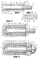
- the expansion dowel shown in FIGS. 1 to 4 consists of an anchor bolt 1 and a surrounding expansion sleeve 2 which is axially displaceable relative to the anchor bolt 1.
- the anchor bolt 1 has a front end 1a in the setting direction and a rear end 1b.
- the central region of the anchor bolt 1 is designed as a cylindrical shaft 1c.
- the rear end region of the shaft 1c carries a thread 1d as a means of engagement for load absorption.
- An extension 1e adjoins the cylindrical shaft 1c in the setting direction.
- the extension 1e is designed as a concave curvature.
- the radius R of the curvature corresponds approximately to the largest diameter D of the anchor bolt 1.
- the concave curvature of the extension 1e results in an increasing conicity towards the front end 1a.
- the expansion sleeve 2 has a bore 2a, the inside diameter of which corresponds approximately to the outside diameter of the shaft 1c.
- the expansion sleeve is provided with the longitudinal slots 2b which serve for radial expansion.
- the expansion sleeve 2 At its front end 2c in the setting direction, the expansion sleeve 2 has a circumferential cutting tooth 2d.
- two further cutting teeth 2e, 2f are arranged on the jacket of the expansion sleeve 2.
- the cutting teeth 2d, 2e, 2f have a substantially sawtooth-shaped profile that is open towards the casing, the steep flanks being directed towards the front end 2c and the flat flanks being directed against the setting direction.
- the expansion sleeve 2 is provided with a cross-sectional taper formed by an annular groove 2g. This cross-sectional taper serves to improve the deformation of the expansion sleeve during the setting process.
- the expansion sleeve 2 has in its rear end region one or more impressions 2h, which create projections on the inside of the thread 1d and serve to axially secure the expansion sleeve 2 on the anchor bolt 1.
- the radially measured depth t of the constrictions forming the cutting teeth 2d, 2e, 2f decreases counter to the setting direction. This decreasing depth ensures that the spaces between the cutting teeth 2d, 2e, 2f are filled by the receiving material removed from the cutting teeth and that the receiving material is wedged when the anchor bolt is subjected to tensile stress.
- the expansion anchor is inserted into a borehole 3a of a receiving material 3.
- the anchor bolt 1 is supported with its front end 1a on the bottom of the borehole 3b.
- the expansion sleeve 2 is with the help of a tubular setting tool 4 have been driven over the extension 1e of the anchor bolt 1.
- the projections created by the embossments 2h on the inside of the expansion sleeve 2 were sheared off.
- the cutting teeth 2d, 2e, 2f engage in the wall of the borehole 3a and remove part of the receiving material 3. This results in a positive connection between the expansion sleeve 2 and the receiving material 3.
- the annular groove 2g arranged on the outside of the expansion sleeve 2 and the longitudinal slots 2b facilitate the radial expansion of the expansion sleeve 2.
- a component 5 to be fastened is attached to the thread 1d of the anchor bolt 1 and fastened by means of a washer 6 and a nut 7 screwed onto the thread 1b.
- a crack 3c in the receiving material 3.
- the opening of this crack 3c enables the anchor bolt 1 to be drawn into the expansion sleeve 2 which is positively anchored in the receiving material 3.
- the cone of the extension 1e which is very strong at the front end 1a, is the expansion effect of the expansion anchor on the crack 3c low. After an initial spread, this finally comes to a standstill.
Claims (6)
- Cheville expansible pourvue d'un boulon d'ancrage (1), dont la tige cylindrique (1c) présente un élargissement (1e) s'étendant dans la direction de pose, formé par un épanouissement à courbure concave et la tige (1c), à l'extrémité éloignée de cet élargissement, porte des moyens d'application (1d) en vue de la réception d'une charge, le boulon d'ancrage (1) étant entouré par une douille expansible (2) déplaçable par rapport à celui-ci, fendue longitudinalement au moins partiellement depuis l'extrémité du côté de la direction de pose, dont le diamètre intérieur correspond au diamètre extérieur de la tige (1c) et la douille expansible (2) présente,à son éxtrémité antérieure (2c) dans la direction de pose,une dent de coupe circulaire (2d), qui possède un profil ouvert en direction de la surface latérale, sensiblement en forme de dents de scie avec des flancs raides orientés dans la direction de pose, caractérisée en ce que l'élargissement (1e),formé par un épanouissement à courbure concave, se raccorde dans la direction de pose à la tige cylindrique (1c) du boulon d'ancrage (1), d'autres dents de coupe semblables (2e,2f) étant disposées sur la surface latérale de la douille expansible (2) dans la direction opposée à la direction de pose, juxtaposées à la dent de coupe circulaire (2d), et la douille expansible (2) présente une réduction de section dans la zone adjacente aux dents de coupe (2d,2e,2f) dans la direction opposée à la direction de pose.
- Cheville expansible selon la revendication 1, caracterisée en ce que trois dents de coupe (2d,2e,2f) en tout sont prévues.
- Cheville expansible selon la revendication 1 ou 2, caractérisée en ce que la profondeur (t), mesurée radialement, des rétrécissements formant les dents de coupe diminue dans la direction opposée à la direction de pose.
- Cheville expansible selon l'une quelconque des revendications 1 à 3, caractérisée en ce que l'épanouissement à courbure concave est formé par un rayon (R).
- Cheville expansible selon la revendication 4, caractérisée en ce que le rayon (R) correspond approximativement au plus grand diamètre (D) du boulon d'ancrage (1).
- Cheville expansible selon l'une quelconque des revendications 1 à 5, caractérisée en ce que la réduction de section est formée par une gorge annulaire (2g) pratiquée sur le côté extérieur de la douille expansible (2).
Priority Applications (1)
| Application Number | Priority Date | Filing Date | Title |
|---|---|---|---|
| AT88112085T ATE73524T1 (de) | 1987-09-22 | 1988-07-27 | Spreizduebel. |
Applications Claiming Priority (2)
| Application Number | Priority Date | Filing Date | Title |
|---|---|---|---|
| DE19873731818 DE3731818A1 (de) | 1987-09-22 | 1987-09-22 | Spreizduebel |
| DE3731818 | 1987-09-22 |
Publications (2)
| Publication Number | Publication Date |
|---|---|
| EP0308619A1 EP0308619A1 (fr) | 1989-03-29 |
| EP0308619B1 true EP0308619B1 (fr) | 1992-03-11 |
Family
ID=6336559
Family Applications (1)
| Application Number | Title | Priority Date | Filing Date |
|---|---|---|---|
| EP88112085A Expired - Lifetime EP0308619B1 (fr) | 1987-09-22 | 1988-07-27 | Chéville à expansion |
Country Status (9)
| Country | Link |
|---|---|
| US (1) | US4984945A (fr) |
| EP (1) | EP0308619B1 (fr) |
| JP (2) | JPS6483907A (fr) |
| KR (1) | KR910010086B1 (fr) |
| AT (1) | ATE73524T1 (fr) |
| AU (1) | AU610640B2 (fr) |
| CA (1) | CA1320363C (fr) |
| DE (2) | DE3731818A1 (fr) |
| ES (1) | ES2029501T3 (fr) |
Cited By (2)
| Publication number | Priority date | Publication date | Assignee | Title |
|---|---|---|---|---|
| EP3118469A1 (fr) | 2015-07-15 | 2017-01-18 | fischerwerke GmbH & Co. KG | Ancre contre-depouillee auto-taraudeuse |
| DE102016110162A1 (de) | 2015-07-15 | 2017-01-19 | Fischerwerke Gmbh & Co. Kg | Selbstschneidender Hinterschnittanker |
Families Citing this family (43)
| Publication number | Priority date | Publication date | Assignee | Title |
|---|---|---|---|---|
| DE4026816A1 (de) * | 1990-08-24 | 1992-02-27 | Grohe Armaturen Friedrich | Steckverbindung |
| JPH0462911U (fr) * | 1990-10-04 | 1992-05-28 | ||
| DE4116149A1 (de) * | 1991-05-17 | 1992-11-19 | Hilti Ag | Spreizduebel mit reibungsmindernder beschichtung |
| DE4208834A1 (de) * | 1992-03-19 | 1993-09-23 | Fischer Artur Werke Gmbh | Bolzenanker zum verankern in einem bohrloch eines bauteiles mittels einem klebstoffkoerper |
| DE4213941A1 (de) * | 1992-04-28 | 1993-11-11 | Arndt Dr Ing Bergner | Dübel |
| DE9303899U1 (fr) * | 1993-03-17 | 1993-05-13 | Liebig, Heinrich, 6102 Pfungstadt, De | |
| DE4344421A1 (de) * | 1993-12-24 | 1995-06-29 | Wuerth Adolf Gmbh & Co Kg | Spreizdübel |
| DE4344410A1 (de) * | 1993-12-24 | 1995-06-29 | Wuerth Adolf Gmbh & Co Kg | Spreizdübel |
| DE19504216A1 (de) * | 1995-02-09 | 1996-08-22 | Fischer Artur Werke Gmbh | Spreizdübel für die Verankerung in einem eine Hinterschneidung aufweisenden Bohrloch |
| DE59701561D1 (de) * | 1996-06-05 | 2000-06-08 | Hilti Ag | Hinterschnittanker |
| DE19652278A1 (de) * | 1996-12-16 | 1998-06-18 | Hilti Ag | Selbstschneidender Hinterschnittdübel |
| DE19652280A1 (de) * | 1996-12-16 | 1998-06-18 | Hilti Ag | Selbstschneidender Hinterschnittdübel |
| DE19848704A1 (de) * | 1998-10-22 | 2000-04-27 | Hilti Ag | Hinterschnittdübel |
| US6213697B1 (en) | 2000-02-25 | 2001-04-10 | Illinois Tool Works Inc. | Self-cutting expansion anchor |
| FR2818333B1 (fr) * | 2000-12-20 | 2003-09-26 | Prospection & Inventions | Cheville a douille expansible pour materiau dur |
| US20070243037A1 (en) * | 2006-02-28 | 2007-10-18 | Pratt John D | Blind bolt fastener |
| AU2007220986A1 (en) * | 2006-02-28 | 2007-09-07 | Monogram Aerospace Fasteners, Inc. | Mechanically locked blind bolt fastener |
| US7744320B2 (en) * | 2006-06-05 | 2010-06-29 | Illinois Tool Works Inc. | Anchor bolt and annularly grooved expansion sleeve assembly exhibiting high pull-out resistance, particularly under cracked concrete test conditions |
| US7811037B2 (en) * | 2006-06-05 | 2010-10-12 | Illinois Tool Works Inc. | Anchor bolt and annularly grooved expansion sleeve assembly exhibiting high pull-out resistance, particularly under cracked concrete test conditions |
| WO2008022630A1 (fr) * | 2006-08-22 | 2008-02-28 | Ccg-Concept Consulting Gmbh | Tirant d'ancrage |
| DE102006000486A1 (de) * | 2006-09-28 | 2008-04-10 | Hilti Ag | Ankerstab und Anordnung zum Verstärken von bestehenden Bauteilen gegen Durchstanzen mit einem solchen Ankerstab |
| US8398345B2 (en) * | 2006-10-05 | 2013-03-19 | Monogram Aerospace Fasteners, Inc. | Low profile dual-action disposable clamp |
| WO2008045360A2 (fr) * | 2006-10-05 | 2008-04-17 | Monogram Aerospace Fasteners, Inc. | Bride jetable à double action |
| US8517649B2 (en) * | 2006-10-05 | 2013-08-27 | Monogram Aerospace Fasteners, Inc. | Dual-action disposable clamp |
| DE102007041058A1 (de) * | 2007-08-29 | 2009-03-12 | Zimmer, Günther | Dübel für selbsttätigen Deckplattenhintergriff und dessen Injektionsklebeverfahren |
| ITTO20070146U1 (it) * | 2007-11-29 | 2009-05-30 | Itw Construction Products Ital | Tassello ad espansione |
| WO2010111593A2 (fr) | 2009-03-27 | 2010-09-30 | Monogram Aerospace Fasteners, Inc. | Pièce de fixation de boulon aveugle |
| CN102817893A (zh) * | 2011-06-09 | 2012-12-12 | 郭振春 | 可拆卸膨胀螺栓 |
| CN103174727A (zh) * | 2011-12-22 | 2013-06-26 | 鸿富锦精密工业(深圳)有限公司 | 紧固组件 |
| CN102635616A (zh) * | 2012-04-17 | 2012-08-15 | 王春华 | 自切扩孔锚栓 |
| US20160230397A1 (en) * | 2013-09-13 | 2016-08-11 | Osman Cavit TURUNC | A development method for mounting natural stones on facade coatings easily |
| JP6231506B2 (ja) * | 2015-01-19 | 2017-11-15 | 株式会社ミヤナガ | アンカーボルト |
| EP3073130A1 (fr) | 2015-03-27 | 2016-09-28 | HILTI Aktiengesellschaft | Cheville à expansion |
| DE102016103196A1 (de) * | 2015-07-22 | 2017-01-26 | Fischerwerke Gmbh & Co. Kg | Befestigungsanordnung und Spreizanker |
| EP3121461B1 (fr) * | 2015-07-22 | 2018-09-05 | fischerwerke GmbH & Co. KG | Systeme de fixation et ancre extensible |
| CN106763048A (zh) * | 2016-12-25 | 2017-05-31 | 黄传勇 | 一种膨胀螺栓 |
| CN108506304A (zh) * | 2017-04-15 | 2018-09-07 | 裴志胜 | 一种带有折弯槽的高强抗拔锚固件 |
| EP3499053A1 (fr) | 2017-12-18 | 2019-06-19 | HILTI Aktiengesellschaft | Élément d'ancrage à expansion pourvu d'une rainure annulaire élargie au niveau de la douille à expansion |
| EP3499054A1 (fr) | 2017-12-18 | 2019-06-19 | HILTI Aktiengesellschaft | Élément d'ancrage à expansion pourvu d'une rainure annulaire adaptée à une douille à expansion |
| US11092180B2 (en) | 2018-05-14 | 2021-08-17 | Carl Barrow | Locking dowel assembly |
| CN110145522B (zh) * | 2019-06-19 | 2024-04-02 | 广州花都区乐思富科技有限公司 | 一种膨胀连接件 |
| WO2021197897A1 (fr) * | 2020-04-02 | 2021-10-07 | Fischerwerke Gmbh & Co. Kg | Ancre à contre-dépouille et son procédé d'ancrage |
| US20220162849A1 (en) * | 2021-12-08 | 2022-05-26 | Black & Decker Inc. | Undercut anchor |
Family Cites Families (18)
| Publication number | Priority date | Publication date | Assignee | Title |
|---|---|---|---|---|
| US688756A (en) * | 1900-05-24 | 1901-12-10 | Jacob W Tripp | Expansion-bolt. |
| US2470924A (en) * | 1946-08-29 | 1949-05-24 | South Chester Corp | Fastening device |
| FR1297330A (fr) * | 1961-05-19 | 1962-06-29 | Louis Colin & Fils | Procédé de fixation de pièces mécaniques sur des supports principalement des supports en matière tendre |
| GB1070692A (en) * | 1963-10-14 | 1967-06-01 | Phillips Drill Co | Expansion stud anchor |
| FR1469966A (fr) * | 1965-03-02 | 1967-02-17 | Cheville pour la fixation d'objets dans des matériaux tels que du bois | |
| NL6508503A (fr) * | 1965-07-01 | 1967-01-02 | ||
| US3448651A (en) * | 1967-06-02 | 1969-06-10 | Usm Corp | Expansion bolts |
| DE2221267C3 (de) * | 1971-04-30 | 1978-10-05 | Giorgio Mailand Feige (Italien) | Spreizdübel |
| ZA746402B (en) * | 1974-04-30 | 1975-10-29 | Rawlplug Co Ltd | Bolt anchoring device |
| DE2828497A1 (de) * | 1978-06-29 | 1980-01-17 | Fischer Artur Dr H C | Schlagspreizduebel aus metall |
| JPS55155905A (en) * | 1980-01-31 | 1980-12-04 | Okabe Kk | Manufacture of cylindrical body for anchor |
| DE3025816A1 (de) * | 1980-07-08 | 1982-02-04 | Werkzeugfabrik Fritz Mächtle GmbH & Co KG, 7015 Korntal | Verfahren zum befestigen von lasten mittels spreizanker sowie spreizanker zur durchfuehrung dieses verfahrens |
| DE3134876A1 (de) * | 1981-09-03 | 1983-03-17 | Artur Dr.H.C. 7244 Waldachtal Fischer | Spreizduebel fuer die verankerung in konisch nach innen erweitert hergestellten bohrloechern |
| DE3146027A1 (de) * | 1981-11-20 | 1983-05-26 | Hilti AG, 9494 Schaan | Ankerbolzen mit bolzenkoerper und spreizhuelse |
| DE3246275A1 (de) * | 1982-12-14 | 1984-06-14 | Hilti Ag, Schaan | Spreizduebel |
| DE3315451A1 (de) * | 1983-04-28 | 1984-10-31 | Artur Dr.H.C. 7244 Waldachtal Fischer | Spreizduebel fuer die verankerung in konisch nach innen erweitert hergestellten bohrloechern |
| DE3420375A1 (de) * | 1984-06-01 | 1986-02-20 | Fischer, Artur, Dr.H.C., 7244 Waldachtal | Duebel |
| DE3535262A1 (de) * | 1985-10-03 | 1987-04-09 | Upat Max Langensiepen Kg | Spreizanker |
-
1987
- 1987-09-22 DE DE19873731818 patent/DE3731818A1/de not_active Withdrawn
-
1988
- 1988-07-27 AT AT88112085T patent/ATE73524T1/de not_active IP Right Cessation
- 1988-07-27 DE DE8888112085T patent/DE3869029D1/de not_active Expired - Lifetime
- 1988-07-27 EP EP88112085A patent/EP0308619B1/fr not_active Expired - Lifetime
- 1988-07-27 ES ES198888112085T patent/ES2029501T3/es not_active Expired - Lifetime
- 1988-08-29 JP JP63212630A patent/JPS6483907A/ja active Pending
- 1988-09-09 AU AU22026/88A patent/AU610640B2/en not_active Ceased
- 1988-09-21 CA CA000578011A patent/CA1320363C/fr not_active Expired - Fee Related
- 1988-09-21 KR KR1019880012186A patent/KR910010086B1/ko not_active IP Right Cessation
- 1988-09-22 US US07/247,957 patent/US4984945A/en not_active Expired - Lifetime
-
1997
- 1997-03-13 JP JP1997001653U patent/JP2568893Y2/ja not_active Expired - Lifetime
Cited By (2)
| Publication number | Priority date | Publication date | Assignee | Title |
|---|---|---|---|---|
| EP3118469A1 (fr) | 2015-07-15 | 2017-01-18 | fischerwerke GmbH & Co. KG | Ancre contre-depouillee auto-taraudeuse |
| DE102016110162A1 (de) | 2015-07-15 | 2017-01-19 | Fischerwerke Gmbh & Co. Kg | Selbstschneidender Hinterschnittanker |
Also Published As
| Publication number | Publication date |
|---|---|
| JPS6483907A (en) | 1989-03-29 |
| EP0308619A1 (fr) | 1989-03-29 |
| AU610640B2 (en) | 1991-05-23 |
| DE3869029D1 (de) | 1992-04-16 |
| CA1320363C (fr) | 1993-07-20 |
| JP2568893Y2 (ja) | 1998-04-15 |
| KR910010086B1 (ko) | 1991-12-14 |
| KR890005400A (ko) | 1989-05-13 |
| ES2029501T3 (es) | 1992-08-16 |
| AU2202688A (en) | 1989-03-23 |
| US4984945A (en) | 1991-01-15 |
| JPH09498U (ja) | 1997-09-22 |
| DE3731818A1 (de) | 1989-03-30 |
| ATE73524T1 (de) | 1992-03-15 |
Similar Documents
| Publication | Publication Date | Title |
|---|---|---|
| EP0308619B1 (fr) | Chéville à expansion | |
| EP0308620B1 (fr) | Piston à expansion | |
| EP0318426B1 (fr) | Piston à expansion avec coquille d'expansion et cône d'expansion rétractable | |
| EP0905385B1 (fr) | Cheville d'expansion | |
| EP0192913B1 (fr) | Cheville expansible à indication de serrage | |
| EP0499580B1 (fr) | Outil d'extraction | |
| CH656193A5 (de) | Spreizduebel. | |
| EP0307590B1 (fr) | Cheville à expansion | |
| DE3413854C2 (fr) | ||
| EP0733813B1 (fr) | Cheville à expansion | |
| EP0964168B1 (fr) | Ancre à contre-dépouille | |
| EP0926360B1 (fr) | Cheville pour trou d'ancrage à contre-dépouille | |
| EP0225845A1 (fr) | Cheville à expansion comprenant un appendice sur l'élement extensible | |
| EP0905386B1 (fr) | Cheville d'expansion | |
| EP0995913B1 (fr) | Cheville pour trou de forage à contre-dépouille | |
| EP0171354B1 (fr) | Cheville à écartement | |
| EP0905388A1 (fr) | Boulon d'ancrage | |
| EP0913592B1 (fr) | Cheville à percussion | |
| DE3309006A1 (de) | Befestigungssatz | |
| EP0701068A1 (fr) | Cheville d'ancre d'isolation | |
| EP0893610B1 (fr) | Cheville d'expansion | |
| EP1026413A2 (fr) | Cheville en matière plastique | |
| EP1205674A2 (fr) | Cheville à expansion | |
| WO2001061198A1 (fr) | Cheville a expansion | |
| DE19720033A1 (de) | Spreizanker zum Befestigen an einem Hohlkammern aufweisenden Bauwerk |
Legal Events
| Date | Code | Title | Description |
|---|---|---|---|
| PUAI | Public reference made under article 153(3) epc to a published international application that has entered the european phase |
Free format text: ORIGINAL CODE: 0009012 |
|
| AK | Designated contracting states |
Kind code of ref document: A1 Designated state(s): AT BE CH DE ES FR GB IT LI NL SE |
|
| 17P | Request for examination filed |
Effective date: 19890909 |
|
| 17Q | First examination report despatched |
Effective date: 19900528 |
|
| GRAA | (expected) grant |
Free format text: ORIGINAL CODE: 0009210 |
|
| ITF | It: translation for a ep patent filed |
Owner name: BARZANO' E ZANARDO MILANO S.P.A. |
|
| AK | Designated contracting states |
Kind code of ref document: B1 Designated state(s): AT BE CH DE ES FR GB IT LI NL SE |
|
| REF | Corresponds to: |
Ref document number: 73524 Country of ref document: AT Date of ref document: 19920315 Kind code of ref document: T |
|
| REF | Corresponds to: |
Ref document number: 3869029 Country of ref document: DE Date of ref document: 19920416 |
|
| ET | Fr: translation filed | ||
| GBT | Gb: translation of ep patent filed (gb section 77(6)(a)/1977) | ||
| REG | Reference to a national code |
Ref country code: ES Ref legal event code: FG2A Ref document number: 2029501 Country of ref document: ES Kind code of ref document: T3 |
|
| PLBE | No opposition filed within time limit |
Free format text: ORIGINAL CODE: 0009261 |
|
| STAA | Information on the status of an ep patent application or granted ep patent |
Free format text: STATUS: NO OPPOSITION FILED WITHIN TIME LIMIT |
|
| 26N | No opposition filed | ||
| EAL | Se: european patent in force in sweden |
Ref document number: 88112085.1 |
|
| REG | Reference to a national code |
Ref country code: GB Ref legal event code: IF02 |
|
| PGFP | Annual fee paid to national office [announced via postgrant information from national office to epo] |
Ref country code: NL Payment date: 20040704 Year of fee payment: 17 |
|
| PGFP | Annual fee paid to national office [announced via postgrant information from national office to epo] |
Ref country code: SE Payment date: 20040706 Year of fee payment: 17 |
|
| PGFP | Annual fee paid to national office [announced via postgrant information from national office to epo] |
Ref country code: FR Payment date: 20040708 Year of fee payment: 17 |
|
| PGFP | Annual fee paid to national office [announced via postgrant information from national office to epo] |
Ref country code: AT Payment date: 20040713 Year of fee payment: 17 |
|
| PGFP | Annual fee paid to national office [announced via postgrant information from national office to epo] |
Ref country code: ES Payment date: 20040719 Year of fee payment: 17 |
|
| PGFP | Annual fee paid to national office [announced via postgrant information from national office to epo] |
Ref country code: CH Payment date: 20040729 Year of fee payment: 17 |
|
| PGFP | Annual fee paid to national office [announced via postgrant information from national office to epo] |
Ref country code: BE Payment date: 20040909 Year of fee payment: 17 |
|
| PG25 | Lapsed in a contracting state [announced via postgrant information from national office to epo] |
Ref country code: AT Free format text: LAPSE BECAUSE OF NON-PAYMENT OF DUE FEES Effective date: 20050727 Ref country code: IT Free format text: LAPSE BECAUSE OF NON-PAYMENT OF DUE FEES;WARNING: LAPSES OF ITALIAN PATENTS WITH EFFECTIVE DATE BEFORE 2007 MAY HAVE OCCURRED AT ANY TIME BEFORE 2007. THE CORRECT EFFECTIVE DATE MAY BE DIFFERENT FROM THE ONE RECORDED. Effective date: 20050727 |
|
| PG25 | Lapsed in a contracting state [announced via postgrant information from national office to epo] |
Ref country code: SE Free format text: LAPSE BECAUSE OF NON-PAYMENT OF DUE FEES Effective date: 20050728 Ref country code: ES Free format text: LAPSE BECAUSE OF NON-PAYMENT OF DUE FEES Effective date: 20050728 |
|
| PG25 | Lapsed in a contracting state [announced via postgrant information from national office to epo] |
Ref country code: BE Free format text: LAPSE BECAUSE OF NON-PAYMENT OF DUE FEES Effective date: 20050731 Ref country code: LI Free format text: LAPSE BECAUSE OF NON-PAYMENT OF DUE FEES Effective date: 20050731 Ref country code: CH Free format text: LAPSE BECAUSE OF NON-PAYMENT OF DUE FEES Effective date: 20050731 |
|
| PG25 | Lapsed in a contracting state [announced via postgrant information from national office to epo] |
Ref country code: NL Free format text: LAPSE BECAUSE OF NON-PAYMENT OF DUE FEES Effective date: 20060201 |
|
| REG | Reference to a national code |
Ref country code: CH Ref legal event code: PL |
|
| EUG | Se: european patent has lapsed | ||
| PG25 | Lapsed in a contracting state [announced via postgrant information from national office to epo] |
Ref country code: FR Free format text: LAPSE BECAUSE OF NON-PAYMENT OF DUE FEES Effective date: 20060331 |
|
| NLV4 | Nl: lapsed or anulled due to non-payment of the annual fee |
Effective date: 20060201 |
|
| REG | Reference to a national code |
Ref country code: FR Ref legal event code: ST Effective date: 20060331 |
|
| REG | Reference to a national code |
Ref country code: ES Ref legal event code: FD2A Effective date: 20050728 |
|
| PGFP | Annual fee paid to national office [announced via postgrant information from national office to epo] |
Ref country code: DE Payment date: 20070705 Year of fee payment: 20 |
|
| BERE | Be: lapsed |
Owner name: *HILTI A.G. Effective date: 20050731 |
|
| PGFP | Annual fee paid to national office [announced via postgrant information from national office to epo] |
Ref country code: GB Payment date: 20070725 Year of fee payment: 20 |
|
| REG | Reference to a national code |
Ref country code: GB Ref legal event code: PE20 Expiry date: 20080726 |
|
| PG25 | Lapsed in a contracting state [announced via postgrant information from national office to epo] |
Ref country code: GB Free format text: LAPSE BECAUSE OF EXPIRATION OF PROTECTION Effective date: 20080726 |