EP0308619B1 - Expansion dowel - Google Patents
Expansion dowel Download PDFInfo
- Publication number
- EP0308619B1 EP0308619B1 EP88112085A EP88112085A EP0308619B1 EP 0308619 B1 EP0308619 B1 EP 0308619B1 EP 88112085 A EP88112085 A EP 88112085A EP 88112085 A EP88112085 A EP 88112085A EP 0308619 B1 EP0308619 B1 EP 0308619B1
- Authority
- EP
- European Patent Office
- Prior art keywords
- expansion
- setting direction
- expansible
- cutting teeth
- expansion sleeve
- Prior art date
- Legal status (The legal status is an assumption and is not a legal conclusion. Google has not performed a legal analysis and makes no representation as to the accuracy of the status listed.)
- Expired - Lifetime
Links
- 230000036346 tooth eruption Effects 0.000 claims abstract description 27
- 230000007423 decrease Effects 0.000 claims description 3
- 239000000463 material Substances 0.000 abstract description 16
- 230000037431 insertion Effects 0.000 abstract 2
- 238000003780 insertion Methods 0.000 abstract 2
- 230000014759 maintenance of location Effects 0.000 abstract 1
- 238000000034 method Methods 0.000 description 6
- 230000000694 effects Effects 0.000 description 3
- 230000002349 favourable effect Effects 0.000 description 3
- 238000006073 displacement reaction Methods 0.000 description 2
- 238000010521 absorption reaction Methods 0.000 description 1
- 238000005452 bending Methods 0.000 description 1
- 230000003247 decreasing effect Effects 0.000 description 1
- 230000001419 dependent effect Effects 0.000 description 1
- 239000002360 explosive Substances 0.000 description 1
Images
Classifications
-
- F—MECHANICAL ENGINEERING; LIGHTING; HEATING; WEAPONS; BLASTING
- F16—ENGINEERING ELEMENTS AND UNITS; GENERAL MEASURES FOR PRODUCING AND MAINTAINING EFFECTIVE FUNCTIONING OF MACHINES OR INSTALLATIONS; THERMAL INSULATION IN GENERAL
- F16B—DEVICES FOR FASTENING OR SECURING CONSTRUCTIONAL ELEMENTS OR MACHINE PARTS TOGETHER, e.g. NAILS, BOLTS, CIRCLIPS, CLAMPS, CLIPS OR WEDGES; JOINTS OR JOINTING
- F16B13/00—Dowels or other devices fastened in walls or the like by inserting them in holes made therein for that purpose
- F16B13/04—Dowels or other devices fastened in walls or the like by inserting them in holes made therein for that purpose with parts gripping in the hole or behind the reverse side of the wall after inserting from the front
-
- F—MECHANICAL ENGINEERING; LIGHTING; HEATING; WEAPONS; BLASTING
- F16—ENGINEERING ELEMENTS AND UNITS; GENERAL MEASURES FOR PRODUCING AND MAINTAINING EFFECTIVE FUNCTIONING OF MACHINES OR INSTALLATIONS; THERMAL INSULATION IN GENERAL
- F16B—DEVICES FOR FASTENING OR SECURING CONSTRUCTIONAL ELEMENTS OR MACHINE PARTS TOGETHER, e.g. NAILS, BOLTS, CIRCLIPS, CLAMPS, CLIPS OR WEDGES; JOINTS OR JOINTING
- F16B13/00—Dowels or other devices fastened in walls or the like by inserting them in holes made therein for that purpose
- F16B13/002—Dowels or other devices fastened in walls or the like by inserting them in holes made therein for that purpose self-cutting
- F16B13/004—Dowels or other devices fastened in walls or the like by inserting them in holes made therein for that purpose self-cutting with a drilling sleeve driven against a tapered or spherical plug
-
- F—MECHANICAL ENGINEERING; LIGHTING; HEATING; WEAPONS; BLASTING
- F16—ENGINEERING ELEMENTS AND UNITS; GENERAL MEASURES FOR PRODUCING AND MAINTAINING EFFECTIVE FUNCTIONING OF MACHINES OR INSTALLATIONS; THERMAL INSULATION IN GENERAL
- F16B—DEVICES FOR FASTENING OR SECURING CONSTRUCTIONAL ELEMENTS OR MACHINE PARTS TOGETHER, e.g. NAILS, BOLTS, CIRCLIPS, CLAMPS, CLIPS OR WEDGES; JOINTS OR JOINTING
- F16B13/00—Dowels or other devices fastened in walls or the like by inserting them in holes made therein for that purpose
- F16B13/04—Dowels or other devices fastened in walls or the like by inserting them in holes made therein for that purpose with parts gripping in the hole or behind the reverse side of the wall after inserting from the front
- F16B13/08—Dowels or other devices fastened in walls or the like by inserting them in holes made therein for that purpose with parts gripping in the hole or behind the reverse side of the wall after inserting from the front with separate or non-separate gripping parts moved into their final position in relation to the body of the device without further manual operation
- F16B13/0858—Dowels or other devices fastened in walls or the like by inserting them in holes made therein for that purpose with parts gripping in the hole or behind the reverse side of the wall after inserting from the front with separate or non-separate gripping parts moved into their final position in relation to the body of the device without further manual operation with an expansible sleeve or dowel body driven against a tapered or spherical expander plug
Definitions
- the invention relates to an expansion anchor with an anchor bolt, the cylindrical shaft of which has a concave curvature that extends in the setting direction and the shaft, on the end facing away from this extension, carries attack means for load-bearing, the anchor bolt being displaceable relative to it, at least partially from end of the setting direction is surrounded by longitudinally slotted expansion sleeve, the inside diameter of which corresponds to the outside diameter of the shaft and the expansion sleeve has a circumferential cutting tooth at its front end in the setting direction, which has an essentially sawtooth-shaped profile open to the jacket with a steeper flank pointing in the setting direction.
- Expansion anchors of the type mentioned, known from DE-A-31 46 027, are anchored by the expansion sleeve being driven with radial expansion via the expansion of the anchor bolt supported on the bottom of the borehole.
- the cutting tooth arranged at the front end of the expanding sleeve creates an undercut in the receiving material.
- the expansion sleeve is expanded. Due to the relatively flat cone of the extension of the anchor bolt, very high expansion forces arise with this expansion anchor. These spreading forces can have an explosive effect on the recording material.
- the expansion plug mentioned is therefore only of limited suitability for fastenings in the torn tensile zone of a building.
- the energy required for advancing the expansion sleeve due to the single cutting tooth is relatively high.
- EP-A-0 163 152 discloses an expansion dowel which differs in terms of type, the anchor bolt of which is connected via a thread and has an extension designed as a concave curvature. However, this concave curvature is adjacent to a conical extension opposite to the setting direction. Consequently In a first phase, with a relative displacement between the anchor bolt and the expansion sleeve, this conical widening is decisive for the expansion of the expansion sleeve. This results in a displacement-dependent, uniform expansion of the expansion sleeve in this phase, which is sufficient for an expansion anchor of this known type, for an expansion anchor whose expansion sleeve is intended to perform a cutting function, but is not sufficient.
- a spreading dowel the expansion sleeve of which is capable of performing a cutting function, is known from CH-A-459 665.
- this known expansion dowel is unsuitable for fastenings in the torn pull zone, since the attacking means arranged on the anchor bolt is connected to the expansion sleeve.
- the invention has for its object to provide an expansion dowel that can be set with little energy and has a suitable expansion behavior for fastenings in the cracked tensile zone.
- the extension which is designed as a concave curvature, adjoins the cylindrical shaft of the anchor bolt in the setting direction, further cutting teeth of this type are arranged on the jacket of the expanding sleeve against the setting direction, adjoining the circumferential cutting tooth, and the expanding sleeve in the opposite direction to the setting direction Cutting teeth adjacent area has a cross-sectional taper.
- the concave curvature of the extension creates an increasing conicity in the setting direction.
- the resistance when advancing the expansion sleeve is therefore low at the beginning of the expansion process and then increases.
- the post-expansion behavior of the dowel finally comes to a standstill after the initial expansion, due to the increasing expansion.
- the arrangement of several cutting teeth leads to a distribution of the receiving material to be removed from the borehole wall to the individual cutting teeth according to the principle of a broach. Overloading the cutting teeth is avoided by this distribution.
- the sawtooth-shaped profile of the cutting teeth is preferably designed such that the steeper flank is directed in the setting direction and the flatter flank is directed counter to the setting direction.
- a cross-sectional taper is provided on the area of the expansion sleeve adjacent to the cutting teeth in the opposite direction.
- the tabs formed by the longitudinal slots of the expansion sleeve can be bent outwards without any great effort when running onto the extension of the anchor bolt. Since the cross-sectional taper is only subjected to pressure when the expansion anchor is loaded, the cross-sectional taper has no negative influence on the anchorage value of the anchor.
- the three cutting teeth are preferably arranged at approximately equal axial distances from one another, so that during the setting process each cutting tooth has to remove approximately the same proportion of the receiving material from the borehole wall.
- the cutting teeth are driven into the receiving material on the borehole wall to different degrees.
- the receiving material removed from the cutting teeth fills the gaps between the cutting teeth.
- the radially measured depth of the constrictions forming the cutting teeth advantageously decreases counter to the setting direction.
- the spaces formed by the constrictions thus become smaller against the setting direction. This ensures that the Gaps are filled up by the receiving material removed from the cutting teeth and there is an additional wedge in the area of the gaps that increases the pull-out value.
- the concave curvature is expediently formed by a radius. Such a concave curvature formed by a radius is easy to produce and results in a favorable run-up curve for the expansion sleeve.
- the radius advantageously corresponds approximately to the largest diameter of the anchor bolt.
- a radius in this area results in a good expansion of the expansion sleeve during the setting process and a favorable expansion behavior.
- a radius corresponding approximately to the largest diameter of the anchor bolt prevents the occurrence of a notch effect.
- the cross-sectional taper is advantageously formed by an annular groove arranged on the outside of the expansion sleeve.
- Such an annular groove arranged on the outside of the expansion sleeve is relatively easy to produce. Since the ring groove at After the outward bending of the segments of the expansion sleeve formed by the longitudinal slots is at least partially closed, the annular groove practically does not lead to a reduction in the contact area of the expansion sleeve on the borehole wall.
- the expansion dowel shown in FIGS. 1 to 4 consists of an anchor bolt 1 and a surrounding expansion sleeve 2 which is axially displaceable relative to the anchor bolt 1.
- the anchor bolt 1 has a front end 1a in the setting direction and a rear end 1b.
- the central region of the anchor bolt 1 is designed as a cylindrical shaft 1c.
- the rear end region of the shaft 1c carries a thread 1d as a means of engagement for load absorption.
- An extension 1e adjoins the cylindrical shaft 1c in the setting direction.
- the extension 1e is designed as a concave curvature.
- the radius R of the curvature corresponds approximately to the largest diameter D of the anchor bolt 1.
- the concave curvature of the extension 1e results in an increasing conicity towards the front end 1a.
- the expansion sleeve 2 has a bore 2a, the inside diameter of which corresponds approximately to the outside diameter of the shaft 1c.
- the expansion sleeve is provided with the longitudinal slots 2b which serve for radial expansion.
- the expansion sleeve 2 At its front end 2c in the setting direction, the expansion sleeve 2 has a circumferential cutting tooth 2d.
- two further cutting teeth 2e, 2f are arranged on the jacket of the expansion sleeve 2.
- the cutting teeth 2d, 2e, 2f have a substantially sawtooth-shaped profile that is open towards the casing, the steep flanks being directed towards the front end 2c and the flat flanks being directed against the setting direction.
- the expansion sleeve 2 is provided with a cross-sectional taper formed by an annular groove 2g. This cross-sectional taper serves to improve the deformation of the expansion sleeve during the setting process.
- the expansion sleeve 2 has in its rear end region one or more impressions 2h, which create projections on the inside of the thread 1d and serve to axially secure the expansion sleeve 2 on the anchor bolt 1.
- the radially measured depth t of the constrictions forming the cutting teeth 2d, 2e, 2f decreases counter to the setting direction. This decreasing depth ensures that the spaces between the cutting teeth 2d, 2e, 2f are filled by the receiving material removed from the cutting teeth and that the receiving material is wedged when the anchor bolt is subjected to tensile stress.
- the expansion anchor is inserted into a borehole 3a of a receiving material 3.
- the anchor bolt 1 is supported with its front end 1a on the bottom of the borehole 3b.
- the expansion sleeve 2 is with the help of a tubular setting tool 4 have been driven over the extension 1e of the anchor bolt 1.
- the projections created by the embossments 2h on the inside of the expansion sleeve 2 were sheared off.
- the cutting teeth 2d, 2e, 2f engage in the wall of the borehole 3a and remove part of the receiving material 3. This results in a positive connection between the expansion sleeve 2 and the receiving material 3.
- the annular groove 2g arranged on the outside of the expansion sleeve 2 and the longitudinal slots 2b facilitate the radial expansion of the expansion sleeve 2.
- a component 5 to be fastened is attached to the thread 1d of the anchor bolt 1 and fastened by means of a washer 6 and a nut 7 screwed onto the thread 1b.
- a crack 3c in the receiving material 3.
- the opening of this crack 3c enables the anchor bolt 1 to be drawn into the expansion sleeve 2 which is positively anchored in the receiving material 3.
- the cone of the extension 1e which is very strong at the front end 1a, is the expansion effect of the expansion anchor on the crack 3c low. After an initial spread, this finally comes to a standstill.
Abstract
Description
Die Erfindung betrifft einen Spreizdübel mit einem Ankerbolzen, dessen zylindrischer Schaft eine als konkave Wölbung ausgebildete, in Setzrichtung verlaufende Erweiterung aufweist und der Schaft, an dem dieser Erweiterung abgewandten Ende Angriffsmittel zur Lastaufnahme trägt, wobei der Ankerbolzen von einer relativ dazu verschiebbaren, zumindest teilweise vom setzrichtungsseitigen Ende her längsgeschlitzten Spreizhülse umgeben ist, deren Innendurchmesser dem Aussendurchmesser des Schaftes entspricht und die Spreizhülse an ihrem in Setzrichtung vorderen Ende einen umlaufenden Schneidzahn aufweist, der ein im wesentlichen sägezahnförmiges, zum Mantel hin offenes Profil mit in Setzrichtung weisender steilerer Flanke besitzt.The invention relates to an expansion anchor with an anchor bolt, the cylindrical shaft of which has a concave curvature that extends in the setting direction and the shaft, on the end facing away from this extension, carries attack means for load-bearing, the anchor bolt being displaceable relative to it, at least partially from end of the setting direction is surrounded by longitudinally slotted expansion sleeve, the inside diameter of which corresponds to the outside diameter of the shaft and the expansion sleeve has a circumferential cutting tooth at its front end in the setting direction, which has an essentially sawtooth-shaped profile open to the jacket with a steeper flank pointing in the setting direction.
Spreizdübel der genannten, aus der DE-A-31 46 027 bekannten Art werden verankert, indem die Spreizhülse unter radialer Aufweitung über die Erweiterung des sich am Bohrlochgrund abstützenden Ankerbolzens getrieben wird. Der am vorderen Ende der Spreizhülse angeordnete Schneidzahn schafft sich dabei selbst einen Hinterschnitt im Aufnahmematerial. Beim Aufbringen einer Zuglast am Ankerbolzen erfolgt eine Nachspreizung der Spreizhülse. Aufgrund des relativ flachen Konus der Erweiterung des Ankerbolzens entstehen bei diesem Spreizdübel sehr hohe Spreizkräfte. Diese Spreizkräfte können eine Sprengwirkung auf das Aufnahmematerial ausüben. Der genannte Spreizdübel ist daher nur bedingt für Befestigungen in der gerissenen Zugzone eines Bauwerkes geeignet. Ausserdem ist der Energiebedarf beim Vortreiben der Spreizhülse infolge des einzigen Schneidzahnes relativ hoch.Expansion anchors of the type mentioned, known from DE-A-31 46 027, are anchored by the expansion sleeve being driven with radial expansion via the expansion of the anchor bolt supported on the bottom of the borehole. The cutting tooth arranged at the front end of the expanding sleeve creates an undercut in the receiving material. When a tensile load is applied to the anchor bolt, the expansion sleeve is expanded. Due to the relatively flat cone of the extension of the anchor bolt, very high expansion forces arise with this expansion anchor. These spreading forces can have an explosive effect on the recording material. The expansion plug mentioned is therefore only of limited suitability for fastenings in the torn tensile zone of a building. In addition, the energy required for advancing the expansion sleeve due to the single cutting tooth is relatively high.
Aus der EP-A-0 163 152 ist ein gattungsmässig abweichender Spreizdübel bekannt, dessen Ankerbolzen über ein Gewinde verbunden eine als konkave Wölbung ausgebildete Erweiterung aufweist. Allerdings ist dieser konkaven Wölbung entgegen der Setzrichtung eine konische Erweiterung benachbart. Somit ist in einer ersten Phase bei einer Relativverschiebung zwischen Ankerbolzen und Spreizhülse diese konische Erweiterung für die Aufweitung der Spreizhülse massgebend. Dadurch erfolgt in dieser Phase ein wegabhängiges, gleichmässiges Aufweiten der Spreizhülse, was für einen Spreizdübel dieser bekannten Gattung genügt, für einen Spreizdübel, dessen Spreizhülse eine Schneidfunktion erfüllen soll, jedoch nicht ausreicht.EP-A-0 163 152 discloses an expansion dowel which differs in terms of type, the anchor bolt of which is connected via a thread and has an extension designed as a concave curvature. However, this concave curvature is adjacent to a conical extension opposite to the setting direction. Consequently In a first phase, with a relative displacement between the anchor bolt and the expansion sleeve, this conical widening is decisive for the expansion of the expansion sleeve. This results in a displacement-dependent, uniform expansion of the expansion sleeve in this phase, which is sufficient for an expansion anchor of this known type, for an expansion anchor whose expansion sleeve is intended to perform a cutting function, but is not sufficient.
Einen Spreizdübel, dessen Spreizhülse in der Lage ist, eine Schneidfunktion auszuüben, ist aus der CH-A-459 665 bekannt. Allerdings ist dieser bekannte Spreizdübel für Befestigungen in der gerissenen Zugzone ungeeignet, da das am Ankerbolzen angeordnete Angriffsmittel mit der Spreizhülse verbunden ist.A spreading dowel, the expansion sleeve of which is capable of performing a cutting function, is known from CH-A-459 665. However, this known expansion dowel is unsuitable for fastenings in the torn pull zone, since the attacking means arranged on the anchor bolt is connected to the expansion sleeve.
Der Erfindung liegt die Aufgabe zugrunde, einen Spreizdübel zu schaffen, der mit geringem Energieaufwand setzbar ist und der ein für Befestigungen in der gerissenen Zugzone geeignetes Nachspreizverhalten aufweist.The invention has for its object to provide an expansion dowel that can be set with little energy and has a suitable expansion behavior for fastenings in the cracked tensile zone.
Erfindungsgemäss wird dies dadurch erreicht, dass die als konkave Wölbung ausgebildete Erweiterung in Setzrichtung an den zylindrischen Schaft des Ankerbolzens anschliesst, am Mantel der Spreizhülse entgegen der Setzrichtung anschliessend an den umlaufenden Schneidzahn weitere derartige Schneidzähne angeordnet sind und die Spreizhülse in dem entgegen der Setzrichtung an die Schneidzähne angrenzenden Bereich eine Querschnittsverjüngung aufweist.According to the invention, this is achieved in that the extension, which is designed as a concave curvature, adjoins the cylindrical shaft of the anchor bolt in the setting direction, further cutting teeth of this type are arranged on the jacket of the expanding sleeve against the setting direction, adjoining the circumferential cutting tooth, and the expanding sleeve in the opposite direction to the setting direction Cutting teeth adjacent area has a cross-sectional taper.
Die konkave Wölbung der Erweiterung schafft eine in Setzrichtung zunehmende Konizität. Der Widerstand beim Vortreiben der Spreizhülse ist daher zu Beginn des Spreizvorganges gering und nimmt anschliessend zu. Beim Nachspreizverhalten des Dübels kommt es nach anfänglichem Nachspreizen schliesslich infolge der zunehmenden Erweiterung zu einem Stillstand.The concave curvature of the extension creates an increasing conicity in the setting direction. The resistance when advancing the expansion sleeve is therefore low at the beginning of the expansion process and then increases. The post-expansion behavior of the dowel finally comes to a standstill after the initial expansion, due to the increasing expansion.
Die Anordnung mehrerer Schneizähne führt nach dem Prinzip einer Räumnadel zu einer Verteilung des an der Bohrlochwandung abzutragenden Aufnahmematerials auf die einzelnen Schneidzähne. Durch diese Verteilung wird eine Ueberbelastung der Schneidzähne vermieden. Das sägezahnförmige Profil der Schneidzähne ist vorzugsweise so ausgebildet, dass die steilere Flanke in Setzrichtung und flachere Flanke entgegen der Setzrichtung gerichtet ist.The arrangement of several cutting teeth leads to a distribution of the receiving material to be removed from the borehole wall to the individual cutting teeth according to the principle of a broach. Overloading the cutting teeth is avoided by this distribution. The sawtooth-shaped profile of the cutting teeth is preferably designed such that the steeper flank is directed in the setting direction and the flatter flank is directed counter to the setting direction.
Beim Setzvorgang erfolgt eine relativ starke Verformung der Spreizhülse im Spreizbereich. Um diese Verformung der Spreizhülse zu erleichtern, ist an dem entgegen der Setzrichtung an die Schneidzähne angrenzenden Bereich der Spreizhülse eine Querschnittsverjüngung vorgesehen. Durch eine solche Querschnittsverjüngung können die durch die Längsschlitze der Spreizhülse gebildeten Lappen ohne grösseren Kraftaufwand beim Auflaufen auf die Erweiterung des Ankerbolzens nach aussen gebogen werden. Da die Querschnittsverjüngung bei der Belastung des Spreizdübels nur auf Druck beansprucht wird, hat die Querschnittsverjüngung auf den Verankerungswert des Dübels keinen negativen Einfluss.During the setting process, there is a relatively strong deformation of the expansion sleeve in the expansion area. In order to facilitate this deformation of the expansion sleeve, a cross-sectional taper is provided on the area of the expansion sleeve adjacent to the cutting teeth in the opposite direction. By means of such a cross-sectional tapering, the tabs formed by the longitudinal slots of the expansion sleeve can be bent outwards without any great effort when running onto the extension of the anchor bolt. Since the cross-sectional taper is only subjected to pressure when the expansion anchor is loaded, the cross-sectional taper has no negative influence on the anchorage value of the anchor.
Für eine günstige Verteilung der beim Abtragen des Aufnahmematerials an der Bohrlochwandung auftretenden Kräfte ist es zweckmässig, insgesamt drei Schneidzähne vorzusehen. Die drei Schneidzähne werden vorzugsweise etwa in gleichen axialen Abständen voneinander angeordnet, so dass beim Setzvorgang jeder Schneidzahn etwa den gleichen Anteil des Aufnahmematerials an der Bohrlochwandung abzutragen hat.For a favorable distribution of the forces occurring when the receiving material is removed from the borehole wall, it is expedient to provide a total of three cutting teeth. The three cutting teeth are preferably arranged at approximately equal axial distances from one another, so that during the setting process each cutting tooth has to remove approximately the same proportion of the receiving material from the borehole wall.
Beim Setzvorgang werden die Schneidzähne unterschiedlich weit in das Aufnahmematerial an der Bohrlochwandung eingetrieben. Das von den Schneidzähnen abgetragene Aufnahmematerial füllt dabei die zwischen den Schneidzähnen angeordneten Zwischenräume auf. Die radial gemessene Tiefe der die Schneidzähne bildenden Einschnürungen nimmt vorteilhafterweise entgegen der Setzrichtung ab. Die durch die Einschnürungen gebildeten Zwischenräume werden somit entgegen der Setzrichtung kleiner. Dadurch wird gewährleistet, dass die Zwischenräume durch das von den Schneidzähnen abgetragene Aufnahmematerial aufgefüllt werden und es im Bereich der Zwischenräume zu einer zusätzlichen, den Auszugswert erhöhenden Verkeilung kommt.During the setting process, the cutting teeth are driven into the receiving material on the borehole wall to different degrees. The receiving material removed from the cutting teeth fills the gaps between the cutting teeth. The radially measured depth of the constrictions forming the cutting teeth advantageously decreases counter to the setting direction. The spaces formed by the constrictions thus become smaller against the setting direction. This ensures that the Gaps are filled up by the receiving material removed from the cutting teeth and there is an additional wedge in the area of the gaps that increases the pull-out value.
Die konkave Wölbung wird zweckmässigerweise von einem Radius gebildet. Eine solche, durch einen Radius gebildete konkave Wölbung ist einfach herstellbar und ergibt eine günstige Auflaufkurve für die Spreizhülse.The concave curvature is expediently formed by a radius. Such a concave curvature formed by a radius is easy to produce and results in a favorable run-up curve for the expansion sleeve.
Der Radius entspricht vorteilhafterweise etwa dem grössten Durchmesser des Ankerbolzens. Ein in diesem Bereich liegender Radius ergibt eine gute Aufspreizung der Spreizhülse beim Setzvorgang und ein günstiges Nachspreizverhalten. Ausserdem verhindert ein etwa dem grössten Durchmesser des Ankerbolzens entsprechender Radius das Auftreten einer Kerbwirkung.The radius advantageously corresponds approximately to the largest diameter of the anchor bolt. A radius in this area results in a good expansion of the expansion sleeve during the setting process and a favorable expansion behavior. In addition, a radius corresponding approximately to the largest diameter of the anchor bolt prevents the occurrence of a notch effect.
Die Querschnittsverjüngung ist vorteilhaft durch eine an der Aussenseite der Spreizhülse angeordnete Ringnut gebildet. Eine solche, an der Aussenseite der Spreizhülse angeordnete Ringnut ist relativ einfach herstellbar. Da die Ringnut beim Nachaussenbiegen der durch die Längsschlitze gebildeten Segmente der Spreizhülse wenigstens teilweise geschlossen wird, führt die Ringnut praktisch nicht zu einer Verkleinerung der Anlagefläche der Spreizhülse an der Bohrlochwandung.The cross-sectional taper is advantageously formed by an annular groove arranged on the outside of the expansion sleeve. Such an annular groove arranged on the outside of the expansion sleeve is relatively easy to produce. Since the ring groove at After the outward bending of the segments of the expansion sleeve formed by the longitudinal slots is at least partially closed, the annular groove practically does not lead to a reduction in the contact area of the expansion sleeve on the borehole wall.
Die Erfindung soll nachstehend anhand der sie beispielsweise wiedergebenden Zeichnungen näher erläutert werden. Es zeigen:
- Fig. 1
- einen erfindungsgemässen Spreizdübel, in ungespreiztem Zustand,
- Fig. 2
- einen Ausschnitt des in Fig. 1 dargestellten Spreizdübels, in vergrössertem Massstab,
- Fig. 3
- den Spreizdübel gemäss Fig. 1 nach dem Vortreiben der Spreizhülse,
- Fig. 4
- den Spreizdübel gemäss Fig. 1 bis 3, in fertig verankertem Zustand.
- Fig. 1
- an expansion dowel according to the invention, in an unexpanded state,
- Fig. 2
- 1 shows a section of the expansion anchor shown in FIG. 1, on an enlarged scale,
- Fig. 3
- 1 after advancing the expansion sleeve,
- Fig. 4
- 1 to 3, in the fully anchored state.
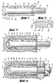
Der aus Fig. 1 bis 4 ersichtliche Spreizdübel besteht aus einem Ankerbolzen 1 und einer diesen umgebenden, gegenüber dem Ankerbolzen 1 axial verschiebbaren Spreizhülse 2. Der Ankerbolzen 1 weist ein in Setzrichtung vorderes Ende 1a und ein rückwärtiges Ende 1b auf. Der mittlere Bereich des Ankerbolzens 1 ist als zylindrischer Schaft 1c ausgebildet. Der rückwärtige Endbereich des Schaftes 1c trägt ein Gewinde 1d als Angriffsmittel zur Lastaufnahme. An den zylindrischen Schaft 1c schliesst sich in Setzrichtung eine Erweiterung 1e an. Die Erweiterung 1e ist als konkave Wölbung ausgebildet. Der Radius R der Wölbung entspricht etwa dem grössten Durchmesser D des Ankerbolzens 1. Die konkave Wölbung der Erweiterung 1e ergibt eine zum vorderen Ende 1a zunehmende Konizität.The expansion dowel shown in FIGS. 1 to 4 consists of an
Die Spreizhülse 2 weist eine Bohrung 2a auf, deren Innendurchmesser etwa dem Aussendurchmesser des Schaftes 1c entspricht. Die Spreizhülse ist mit der radialen Aufweitbarkeit dienenden Längsschlitzen 2b versehen. An ihrem in Setzrichtung vorderen Ende 2c weist die Spreizhülse 2 einen umlaufenden Schneidzahn 2d auf. Entgegen der Setzrichtung sind am Mantel der Spreizhülse 2 zwei weitere Schneidzähne 2e, 2f angeordnet. Die Schneidzähne 2d, 2e, 2f weisen ein im wesentlichen sägezahnförmiges, zum Mantel hin offenes Profil auf, wobei die steilen Flanken gegen das vordere Ende 2c und die flachen Flanken entgegen der Setzrichtung gerichtet sind. In dem entgegen der Setzrichtung an die Schneidzähne 2d, 2e, 2f angrenzenden Bereich ist die Spreizhülse 2 mit einer durch eine Ringnut 2g gebildeten Querschnittsverjüngung versehen. Diese Querschnittsverjüngung dient einer besseren Verformung der Spreizhülse beim Setzvorgang. Die Spreizhülse 2 weist in ihrem rückwärtigen Endbereich eine oder mehrere Einprägungen 2h auf, welche auf der Innenseie in das Gewinde 1d eingreifende Vorsprünge schaffen und zum axialen Sichern der Spreizhülse 2 auf dem Ankerbolzen 1 dienen.The
Wie insbesondere Fig. 2 zeigt, nimmt die radial gemessene Tiefe t der die Schneidzähne 2d, 2e, 2f bildenden Einschnürungen entgegen der Setzrichtung ab. Durch diese abnehmende Tiefe wird gewährleistet, dass die Zwischenräume zwischen den Schneidzähnen 2d, 2e, 2f durch das von den Schneidzähnen abgetragene Aufnahmematerial gefüllt werden und es bei einer Zugbelastung des Ankerbolzens zu einer Verkeilung dieses Aufnahmematerials kommt.As shown in FIG. 2 in particular, the radially measured depth t of the constrictions forming the cutting
In Fig. 3 ist der Spreizdübel in ein Bohrloch 3a eines Aufnahmematerials 3 eingesetzt. Der Ankerbolzen 1 stützt sich dabei mit seinem vorderen Ende 1a am Bohrlochgrund 3b ab. Die Spreizhülse 2 ist mit Hilfe eines rohrförmigen Setzwerkzeuges 4 über die Erweiterung 1e des Ankerbolzens 1 getrieben worden. Die durch die Einprägungen 2h geschaffenen Vorsprünge an der Innenseite der Spreizhülse 2 wurden dabei abgeschert. Die Schneidzähne 2d, 2e, 2f greifen in die Wandung des Bohrloches 3a ein und tragen einen Teil des Aufnahmematerials 3 ab. Somit entsteht eine formschlüssige Verbindung der Spreizhülse 2 mit dem Aufnahmematerial 3. Die an der Aussenseite der Spreizhülse 2 angeordnete Ringnut 2g sowie die Längsschlitze 2b erleichtern das radiale Aufweiten der Spreizhülse 2.In Fig. 3, the expansion anchor is inserted into a
In Fig. 4 ist ein zu befestigendes Bauteil 5 auf das Gewinde 1d des Ankerbolzens 1 aufgesteckt und mittels einer Unterlagscheibe 6 sowie einer auf das Gewinde 1b aufgeschraubten Mutter 7 befestigt. Im Bereich des Bohrloches 3a befindet sich ein Riss 3c im Aufnahmematerial 3. Das Oeffnen dieses Risses 3c ermöglicht ein Einziehen des Ankerbolzens 1 in die im Aufnahmematerial 3 formschlüssig verankerte Spreizhülse 2. Durch die am vorderen Ende 1a sehr starke Konizität der Erweiterung 1e ist die Spreizwirkung des Spreizdübels auf den Riss 3c gering. Nach einer anfänglichen Nachspreizung kommt diese schliesslich zum Stillstand.In FIG. 4, a
Claims (6)
- An expansible dowel having a tie bolt (1), the cylindrical shank (1c) of which has a widening (1e) designed as a concave arch and extending in the setting direction and, at the end remote from this widening, the shank (1c), bears attack means (1d) for the load reception, in which respect the tie bolt (1) is surrounded by an expansible sleeve (2) which is displaceable relative thereto and which is longitudinally slotted at least partially from the setting-direction-sided end and the inside diameter of which corresponds to the outside diameter of the shank (1c) and the expansible sleeve (2) at its front end (2c) in the setting direction has an encircling cutting tooth (2d), which possesses a substantially saw-tooth-shaped profile, open towards the jacket, with the steeper flank pointing in the setting direction, characterised in that the widening (1e) designed as a concave arch is adjacent in the setting direction to the cylindrical shank (1c) of the tie bolt (1), on the jacket of the expansible sleeve (2) contrary to the setting direction adjacent to the encircling cutting tooth (2d) further such cutting teeth (2e, 2f) are arranged and the expansible sleeve (2) in the region contiguous contrary to the setting direction to cutting teeth (2d, 2e, 2f) has a cross-sectional narrowing.
- An expansible dowel according to claim 1, characterised in that altogether three cutting teeth (2d, 2e, 2f) are provided.
- An expansible dowel according to claim 1 or 2, characterised in that the radially measured depth (t) of the constrictions forming the cutting teeth decreases contrary to the setting direction.
- An expansible dowel according to one of claims 1 to 3, characterised in that the concave arch is formed by a radius (R).
- An expansible dowel according to claim 4, characterised in that the radius (R) corresponds approximately to the greatest diameter (D) of the tie bolt (1).
- An expansible dowel according to one of claims 1 to 5, characterised in that the cross-sectional narrowing is formed by an annular groove (2g) arranged on the outside of the expansible sleeve (2).
Priority Applications (1)
| Application Number | Priority Date | Filing Date | Title |
|---|---|---|---|
| AT88112085T ATE73524T1 (en) | 1987-09-22 | 1988-07-27 | EXPANSION DOWEL. |
Applications Claiming Priority (2)
| Application Number | Priority Date | Filing Date | Title |
|---|---|---|---|
| DE19873731818 DE3731818A1 (en) | 1987-09-22 | 1987-09-22 | SPREADING DOWEL |
| DE3731818 | 1987-09-22 |
Publications (2)
| Publication Number | Publication Date |
|---|---|
| EP0308619A1 EP0308619A1 (en) | 1989-03-29 |
| EP0308619B1 true EP0308619B1 (en) | 1992-03-11 |
Family
ID=6336559
Family Applications (1)
| Application Number | Title | Priority Date | Filing Date |
|---|---|---|---|
| EP88112085A Expired - Lifetime EP0308619B1 (en) | 1987-09-22 | 1988-07-27 | Expansion dowel |
Country Status (9)
| Country | Link |
|---|---|
| US (1) | US4984945A (en) |
| EP (1) | EP0308619B1 (en) |
| JP (2) | JPS6483907A (en) |
| KR (1) | KR910010086B1 (en) |
| AT (1) | ATE73524T1 (en) |
| AU (1) | AU610640B2 (en) |
| CA (1) | CA1320363C (en) |
| DE (2) | DE3731818A1 (en) |
| ES (1) | ES2029501T3 (en) |
Cited By (2)
| Publication number | Priority date | Publication date | Assignee | Title |
|---|---|---|---|---|
| EP3118469A1 (en) | 2015-07-15 | 2017-01-18 | fischerwerke GmbH & Co. KG | Self-cutting undercut anchor |
| DE102016110162A1 (en) | 2015-07-15 | 2017-01-19 | Fischerwerke Gmbh & Co. Kg | Self-cutting undercut anchor |
Families Citing this family (43)
| Publication number | Priority date | Publication date | Assignee | Title |
|---|---|---|---|---|
| DE4026816A1 (en) * | 1990-08-24 | 1992-02-27 | Grohe Armaturen Friedrich | CONNECTOR |
| JPH0462911U (en) * | 1990-10-04 | 1992-05-28 | ||
| DE4116149A1 (en) * | 1991-05-17 | 1992-11-19 | Hilti Ag | SPREADING DOWEL WITH FRICTION REDUCING COATING |
| DE4208834A1 (en) * | 1992-03-19 | 1993-09-23 | Fischer Artur Werke Gmbh | Borehole fitted anchor bolt with cylindrical sleeve - has expanding cone at borehole base to act on adhesive sleeve,on bolt driven in. |
| DE4213941A1 (en) * | 1992-04-28 | 1993-11-11 | Arndt Dr Ing Bergner | Dowels |
| DE9303899U1 (en) * | 1993-03-17 | 1993-05-13 | Liebig, Heinrich, 6102 Pfungstadt, De | |
| DE4344421A1 (en) * | 1993-12-24 | 1995-06-29 | Wuerth Adolf Gmbh & Co Kg | Straddling dowel with bolt and truncated cone shaped part |
| DE4344410A1 (en) * | 1993-12-24 | 1995-06-29 | Wuerth Adolf Gmbh & Co Kg | Straddling dowel with bolt and conical-truncated wide part |
| DE19504216A1 (en) * | 1995-02-09 | 1996-08-22 | Fischer Artur Werke Gmbh | Expansion dowels for anchoring in an undercut borehole |
| DE59701561D1 (en) * | 1996-06-05 | 2000-06-08 | Hilti Ag | Undercut anchor |
| DE19652278A1 (en) * | 1996-12-16 | 1998-06-18 | Hilti Ag | Self-tapping undercut dowel |
| DE19652280A1 (en) * | 1996-12-16 | 1998-06-18 | Hilti Ag | Self-tapping undercut dowel |
| DE19848704A1 (en) * | 1998-10-22 | 2000-04-27 | Hilti Ag | Undercut dowels |
| US6213697B1 (en) | 2000-02-25 | 2001-04-10 | Illinois Tool Works Inc. | Self-cutting expansion anchor |
| FR2818333B1 (en) * | 2000-12-20 | 2003-09-26 | Prospection & Inventions | ANCHOR WITH EXPANDABLE SOCKET FOR HARD MATERIAL |
| JP5236504B2 (en) * | 2006-02-28 | 2013-07-17 | モノグラム・エアロスペース・ファスナーズ・インコーポレーテッド | Mechanically locked blind bolt fastener |
| US20070243037A1 (en) * | 2006-02-28 | 2007-10-18 | Pratt John D | Blind bolt fastener |
| US7744320B2 (en) * | 2006-06-05 | 2010-06-29 | Illinois Tool Works Inc. | Anchor bolt and annularly grooved expansion sleeve assembly exhibiting high pull-out resistance, particularly under cracked concrete test conditions |
| US7811037B2 (en) * | 2006-06-05 | 2010-10-12 | Illinois Tool Works Inc. | Anchor bolt and annularly grooved expansion sleeve assembly exhibiting high pull-out resistance, particularly under cracked concrete test conditions |
| WO2008022630A1 (en) * | 2006-08-22 | 2008-02-28 | Ccg-Concept Consulting Gmbh | Sleeve anchor |
| DE102006000486A1 (en) * | 2006-09-28 | 2008-04-10 | Hilti Ag | Anchor rod and arrangement for reinforcing existing components against punching with such an anchor rod |
| US8398345B2 (en) * | 2006-10-05 | 2013-03-19 | Monogram Aerospace Fasteners, Inc. | Low profile dual-action disposable clamp |
| US8511952B2 (en) * | 2006-10-05 | 2013-08-20 | Monogram Aerospace Fasteners, Inc. | Dual-action disposable clamp |
| US8517649B2 (en) * | 2006-10-05 | 2013-08-27 | Monogram Aerospace Fasteners, Inc. | Dual-action disposable clamp |
| DE102007041058A1 (en) * | 2007-08-29 | 2009-03-12 | Zimmer, Günther | Dowel for automatic cover plate rear handle and its injection adhesive method |
| ITTO20070146U1 (en) * | 2007-11-29 | 2009-05-30 | Itw Construction Products Ital | EXPANSION ANCHOR |
| WO2010111593A2 (en) | 2009-03-27 | 2010-09-30 | Monogram Aerospace Fasteners, Inc. | Blind bolt fastener |
| CN102817893A (en) * | 2011-06-09 | 2012-12-12 | 郭振春 | Detachable expansion bolt |
| CN103174727A (en) * | 2011-12-22 | 2013-06-26 | 鸿富锦精密工业(深圳)有限公司 | Fastening component |
| CN102635616A (en) * | 2012-04-17 | 2012-08-15 | 王春华 | Self-tangency broaching anchor bolt |
| WO2015038085A2 (en) * | 2013-09-13 | 2015-03-19 | Turunc Osman Cavit | A development method for mounting natural stones on facade coatings easily |
| JP6231506B2 (en) * | 2015-01-19 | 2017-11-15 | 株式会社ミヤナガ | Anchor bolt |
| EP3073130A1 (en) * | 2015-03-27 | 2016-09-28 | HILTI Aktiengesellschaft | Split anchor |
| EP3121461B1 (en) * | 2015-07-22 | 2018-09-05 | fischerwerke GmbH & Co. KG | Fastening assembly and expansion anchor |
| DE102016103196A1 (en) * | 2015-07-22 | 2017-01-26 | Fischerwerke Gmbh & Co. Kg | Fastening arrangement and expansion anchor |
| CN106763048A (en) * | 2016-12-25 | 2017-05-31 | 黄传勇 | A kind of expansion bolt |
| CN108506304A (en) * | 2017-04-15 | 2018-09-07 | 裴志胜 | A kind of high strong pluck-resistant anchoring piece with bending slot |
| EP3499054A1 (en) | 2017-12-18 | 2019-06-19 | HILTI Aktiengesellschaft | Expansion anchor comprising adapted annular groove on expanding sleeve |
| EP3499053A1 (en) | 2017-12-18 | 2019-06-19 | HILTI Aktiengesellschaft | Expansion anchor comprising broad annular groove on expanding sleeve |
| US11092180B2 (en) | 2018-05-14 | 2021-08-17 | Carl Barrow | Locking dowel assembly |
| CN110145522B (en) * | 2019-06-19 | 2024-04-02 | 广州花都区乐思富科技有限公司 | Expansion connecting piece |
| WO2021197897A1 (en) * | 2020-04-02 | 2021-10-07 | Fischerwerke Gmbh & Co. Kg | Undercut anchor and method for anchoring same |
| US20220162849A1 (en) * | 2021-12-08 | 2022-05-26 | Black & Decker Inc. | Undercut anchor |
Family Cites Families (18)
| Publication number | Priority date | Publication date | Assignee | Title |
|---|---|---|---|---|
| US688756A (en) * | 1900-05-24 | 1901-12-10 | Jacob W Tripp | Expansion-bolt. |
| US2470924A (en) * | 1946-08-29 | 1949-05-24 | South Chester Corp | Fastening device |
| FR1297330A (en) * | 1961-05-19 | 1962-06-29 | Louis Colin & Fils | Method of fixing mechanical parts on supports mainly soft material supports |
| GB1070692A (en) * | 1963-10-14 | 1967-06-01 | Phillips Drill Co | Expansion stud anchor |
| FR1469966A (en) * | 1965-03-02 | 1967-02-17 | Anchor for fixing objects in materials such as wood | |
| NL6508503A (en) * | 1965-07-01 | 1967-01-02 | ||
| US3448651A (en) * | 1967-06-02 | 1969-06-10 | Usm Corp | Expansion bolts |
| DE2221267C3 (en) * | 1971-04-30 | 1978-10-05 | Giorgio Mailand Feige (Italien) | Expansion anchor |
| ZA746402B (en) * | 1974-04-30 | 1975-10-29 | Rawlplug Co Ltd | Bolt anchoring device |
| DE2828497A1 (en) * | 1978-06-29 | 1980-01-17 | Fischer Artur Dr H C | METAL SPREADING DOWEL |
| JPS55155905A (en) * | 1980-01-31 | 1980-12-04 | Okabe Kk | Manufacture of cylindrical body for anchor |
| DE3025816A1 (en) * | 1980-07-08 | 1982-02-04 | Werkzeugfabrik Fritz Mächtle GmbH & Co KG, 7015 Korntal | METHOD FOR FASTENING LOADS BY SPREADING ANCHOR AND SPREADING ANCHOR FOR CARRYING OUT THIS METHOD |
| DE3134876A1 (en) * | 1981-09-03 | 1983-03-17 | Artur Dr.H.C. 7244 Waldachtal Fischer | Expanding dowel for anchoring in bores which are produced such that they widen conically inwards |
| DE3146027A1 (en) * | 1981-11-20 | 1983-05-26 | Hilti AG, 9494 Schaan | ANCHOR BOLT WITH BOLT BODY AND SPREADING SLEEVE |
| DE3246275A1 (en) * | 1982-12-14 | 1984-06-14 | Hilti Ag, Schaan | SPREADING DOWEL |
| DE3315451A1 (en) * | 1983-04-28 | 1984-10-31 | Artur Dr.H.C. 7244 Waldachtal Fischer | Expandable dowel for anchoring in drilled holes which are produced such that they expand conically inwards |
| DE3420375A1 (en) * | 1984-06-01 | 1986-02-20 | Fischer, Artur, Dr.H.C., 7244 Waldachtal | DUEBEL |
| DE3535262A1 (en) * | 1985-10-03 | 1987-04-09 | Upat Max Langensiepen Kg | SPREADING ANCHOR |
-
1987
- 1987-09-22 DE DE19873731818 patent/DE3731818A1/en not_active Withdrawn
-
1988
- 1988-07-27 EP EP88112085A patent/EP0308619B1/en not_active Expired - Lifetime
- 1988-07-27 AT AT88112085T patent/ATE73524T1/en not_active IP Right Cessation
- 1988-07-27 ES ES198888112085T patent/ES2029501T3/en not_active Expired - Lifetime
- 1988-07-27 DE DE8888112085T patent/DE3869029D1/en not_active Expired - Lifetime
- 1988-08-29 JP JP63212630A patent/JPS6483907A/en active Pending
- 1988-09-09 AU AU22026/88A patent/AU610640B2/en not_active Ceased
- 1988-09-21 CA CA000578011A patent/CA1320363C/en not_active Expired - Fee Related
- 1988-09-21 KR KR1019880012186A patent/KR910010086B1/en not_active IP Right Cessation
- 1988-09-22 US US07/247,957 patent/US4984945A/en not_active Expired - Lifetime
-
1997
- 1997-03-13 JP JP1997001653U patent/JP2568893Y2/en not_active Expired - Lifetime
Cited By (2)
| Publication number | Priority date | Publication date | Assignee | Title |
|---|---|---|---|---|
| EP3118469A1 (en) | 2015-07-15 | 2017-01-18 | fischerwerke GmbH & Co. KG | Self-cutting undercut anchor |
| DE102016110162A1 (en) | 2015-07-15 | 2017-01-19 | Fischerwerke Gmbh & Co. Kg | Self-cutting undercut anchor |
Also Published As
| Publication number | Publication date |
|---|---|
| CA1320363C (en) | 1993-07-20 |
| US4984945A (en) | 1991-01-15 |
| DE3869029D1 (en) | 1992-04-16 |
| ATE73524T1 (en) | 1992-03-15 |
| KR890005400A (en) | 1989-05-13 |
| JPS6483907A (en) | 1989-03-29 |
| ES2029501T3 (en) | 1992-08-16 |
| JP2568893Y2 (en) | 1998-04-15 |
| AU2202688A (en) | 1989-03-23 |
| DE3731818A1 (en) | 1989-03-30 |
| AU610640B2 (en) | 1991-05-23 |
| KR910010086B1 (en) | 1991-12-14 |
| JPH09498U (en) | 1997-09-22 |
| EP0308619A1 (en) | 1989-03-29 |
Similar Documents
| Publication | Publication Date | Title |
|---|---|---|
| EP0308619B1 (en) | Expansion dowel | |
| EP0308620B1 (en) | Expansion dowel | |
| EP0318426B1 (en) | Expansion dowel with an expansion sleeve and a retractable expanding cone | |
| EP0905385B1 (en) | Expansion dowel | |
| EP0192913B1 (en) | Expansive dowel with an application indication | |
| EP0499580B1 (en) | Extraction tool | |
| CH656193A5 (en) | SPREADING DOWEL. | |
| EP0307590B1 (en) | Expansion dowel | |
| DE3413854C2 (en) | ||
| EP0733813B1 (en) | Expanding dowel | |
| EP0964168B1 (en) | Undercut anchor | |
| EP0926360B1 (en) | Dowel for an undercut anchor hole | |
| EP0225845A1 (en) | Expansion dowel incorporating an attachment on the expansion element | |
| EP0905386B1 (en) | Expansion dowel | |
| EP0995913B1 (en) | Anchor for borehole with undercut | |
| EP0171354B1 (en) | Expansion dowel | |
| EP0905388A1 (en) | Anchoring bolt | |
| EP0913592B1 (en) | Percussion dowel | |
| DE3309006A1 (en) | Mounting kit | |
| EP0701068A1 (en) | Insulation anchor dowell | |
| EP0893610B1 (en) | Expansion dowel | |
| EP1026413A2 (en) | Plastic dowel | |
| EP1205674A2 (en) | Expansion dowel | |
| WO2001061198A1 (en) | Expansion dowel | |
| DE19720033A1 (en) | Masonry plug for screw fitting into porous wall |
Legal Events
| Date | Code | Title | Description |
|---|---|---|---|
| PUAI | Public reference made under article 153(3) epc to a published international application that has entered the european phase |
Free format text: ORIGINAL CODE: 0009012 |
|
| AK | Designated contracting states |
Kind code of ref document: A1 Designated state(s): AT BE CH DE ES FR GB IT LI NL SE |
|
| 17P | Request for examination filed |
Effective date: 19890909 |
|
| 17Q | First examination report despatched |
Effective date: 19900528 |
|
| GRAA | (expected) grant |
Free format text: ORIGINAL CODE: 0009210 |
|
| ITF | It: translation for a ep patent filed |
Owner name: BARZANO' E ZANARDO MILANO S.P.A. |
|
| AK | Designated contracting states |
Kind code of ref document: B1 Designated state(s): AT BE CH DE ES FR GB IT LI NL SE |
|
| REF | Corresponds to: |
Ref document number: 73524 Country of ref document: AT Date of ref document: 19920315 Kind code of ref document: T |
|
| REF | Corresponds to: |
Ref document number: 3869029 Country of ref document: DE Date of ref document: 19920416 |
|
| ET | Fr: translation filed | ||
| GBT | Gb: translation of ep patent filed (gb section 77(6)(a)/1977) | ||
| REG | Reference to a national code |
Ref country code: ES Ref legal event code: FG2A Ref document number: 2029501 Country of ref document: ES Kind code of ref document: T3 |
|
| PLBE | No opposition filed within time limit |
Free format text: ORIGINAL CODE: 0009261 |
|
| STAA | Information on the status of an ep patent application or granted ep patent |
Free format text: STATUS: NO OPPOSITION FILED WITHIN TIME LIMIT |
|
| 26N | No opposition filed | ||
| EAL | Se: european patent in force in sweden |
Ref document number: 88112085.1 |
|
| REG | Reference to a national code |
Ref country code: GB Ref legal event code: IF02 |
|
| PGFP | Annual fee paid to national office [announced via postgrant information from national office to epo] |
Ref country code: NL Payment date: 20040704 Year of fee payment: 17 |
|
| PGFP | Annual fee paid to national office [announced via postgrant information from national office to epo] |
Ref country code: SE Payment date: 20040706 Year of fee payment: 17 |
|
| PGFP | Annual fee paid to national office [announced via postgrant information from national office to epo] |
Ref country code: FR Payment date: 20040708 Year of fee payment: 17 |
|
| PGFP | Annual fee paid to national office [announced via postgrant information from national office to epo] |
Ref country code: AT Payment date: 20040713 Year of fee payment: 17 |
|
| PGFP | Annual fee paid to national office [announced via postgrant information from national office to epo] |
Ref country code: ES Payment date: 20040719 Year of fee payment: 17 |
|
| PGFP | Annual fee paid to national office [announced via postgrant information from national office to epo] |
Ref country code: CH Payment date: 20040729 Year of fee payment: 17 |
|
| PGFP | Annual fee paid to national office [announced via postgrant information from national office to epo] |
Ref country code: BE Payment date: 20040909 Year of fee payment: 17 |
|
| PG25 | Lapsed in a contracting state [announced via postgrant information from national office to epo] |
Ref country code: AT Free format text: LAPSE BECAUSE OF NON-PAYMENT OF DUE FEES Effective date: 20050727 Ref country code: IT Free format text: LAPSE BECAUSE OF NON-PAYMENT OF DUE FEES;WARNING: LAPSES OF ITALIAN PATENTS WITH EFFECTIVE DATE BEFORE 2007 MAY HAVE OCCURRED AT ANY TIME BEFORE 2007. THE CORRECT EFFECTIVE DATE MAY BE DIFFERENT FROM THE ONE RECORDED. Effective date: 20050727 |
|
| PG25 | Lapsed in a contracting state [announced via postgrant information from national office to epo] |
Ref country code: SE Free format text: LAPSE BECAUSE OF NON-PAYMENT OF DUE FEES Effective date: 20050728 Ref country code: ES Free format text: LAPSE BECAUSE OF NON-PAYMENT OF DUE FEES Effective date: 20050728 |
|
| PG25 | Lapsed in a contracting state [announced via postgrant information from national office to epo] |
Ref country code: BE Free format text: LAPSE BECAUSE OF NON-PAYMENT OF DUE FEES Effective date: 20050731 Ref country code: LI Free format text: LAPSE BECAUSE OF NON-PAYMENT OF DUE FEES Effective date: 20050731 Ref country code: CH Free format text: LAPSE BECAUSE OF NON-PAYMENT OF DUE FEES Effective date: 20050731 |
|
| PG25 | Lapsed in a contracting state [announced via postgrant information from national office to epo] |
Ref country code: NL Free format text: LAPSE BECAUSE OF NON-PAYMENT OF DUE FEES Effective date: 20060201 |
|
| REG | Reference to a national code |
Ref country code: CH Ref legal event code: PL |
|
| EUG | Se: european patent has lapsed | ||
| PG25 | Lapsed in a contracting state [announced via postgrant information from national office to epo] |
Ref country code: FR Free format text: LAPSE BECAUSE OF NON-PAYMENT OF DUE FEES Effective date: 20060331 |
|
| NLV4 | Nl: lapsed or anulled due to non-payment of the annual fee |
Effective date: 20060201 |
|
| REG | Reference to a national code |
Ref country code: FR Ref legal event code: ST Effective date: 20060331 |
|
| REG | Reference to a national code |
Ref country code: ES Ref legal event code: FD2A Effective date: 20050728 |
|
| PGFP | Annual fee paid to national office [announced via postgrant information from national office to epo] |
Ref country code: DE Payment date: 20070705 Year of fee payment: 20 |
|
| BERE | Be: lapsed |
Owner name: *HILTI A.G. Effective date: 20050731 |
|
| PGFP | Annual fee paid to national office [announced via postgrant information from national office to epo] |
Ref country code: GB Payment date: 20070725 Year of fee payment: 20 |
|
| REG | Reference to a national code |
Ref country code: GB Ref legal event code: PE20 Expiry date: 20080726 |
|
| PG25 | Lapsed in a contracting state [announced via postgrant information from national office to epo] |
Ref country code: GB Free format text: LAPSE BECAUSE OF EXPIRATION OF PROTECTION Effective date: 20080726 |