EP0308327B1 - Méthode de détermination de l'usure d'organes de découpe d'un outil en cours de forage d'une formation rocheuse - Google Patents
Méthode de détermination de l'usure d'organes de découpe d'un outil en cours de forage d'une formation rocheuse Download PDFInfo
- Publication number
- EP0308327B1 EP0308327B1 EP88402319A EP88402319A EP0308327B1 EP 0308327 B1 EP0308327 B1 EP 0308327B1 EP 88402319 A EP88402319 A EP 88402319A EP 88402319 A EP88402319 A EP 88402319A EP 0308327 B1 EP0308327 B1 EP 0308327B1
- Authority
- EP
- European Patent Office
- Prior art keywords
- tool
- wear
- weight
- curve
- torque
- Prior art date
- Legal status (The legal status is an assumption and is not a legal conclusion. Google has not performed a legal analysis and makes no representation as to the accuracy of the status listed.)
- Expired - Lifetime
Links
- 238000005553 drilling Methods 0.000 title claims description 35
- 238000000034 method Methods 0.000 title claims description 21
- 230000015572 biosynthetic process Effects 0.000 title claims description 15
- 239000011435 rock Substances 0.000 title claims description 14
- 238000005755 formation reaction Methods 0.000 title description 13
- 238000012360 testing method Methods 0.000 claims description 35
- 238000005259 measurement Methods 0.000 claims description 23
- 230000007423 decrease Effects 0.000 claims description 16
- 238000013101 initial test Methods 0.000 claims 3
- 230000001419 dependent effect Effects 0.000 claims 1
- 230000006870 function Effects 0.000 description 20
- 230000003416 augmentation Effects 0.000 description 3
- 239000012634 fragment Substances 0.000 description 3
- 230000014509 gene expression Effects 0.000 description 3
- 230000035515 penetration Effects 0.000 description 3
- 238000012549 training Methods 0.000 description 3
- 238000013459 approach Methods 0.000 description 2
- 229910003460 diamond Inorganic materials 0.000 description 2
- 239000010432 diamond Substances 0.000 description 2
- 239000004459 forage Substances 0.000 description 2
- 238000005457 optimization Methods 0.000 description 2
- 238000004441 surface measurement Methods 0.000 description 2
- 101100203709 Caenorhabditis elegans spe-11 gene Proteins 0.000 description 1
- 235000019738 Limestone Nutrition 0.000 description 1
- 229920000297 Rayon Polymers 0.000 description 1
- 208000004188 Tooth Wear Diseases 0.000 description 1
- 240000008042 Zea mays Species 0.000 description 1
- 230000000295 complement effect Effects 0.000 description 1
- 238000001514 detection method Methods 0.000 description 1
- 238000011161 development Methods 0.000 description 1
- 230000018109 developmental process Effects 0.000 description 1
- 238000010586 diagram Methods 0.000 description 1
- 230000000694 effects Effects 0.000 description 1
- 239000012530 fluid Substances 0.000 description 1
- 210000001061 forehead Anatomy 0.000 description 1
- 230000010354 integration Effects 0.000 description 1
- 239000006028 limestone Substances 0.000 description 1
- 239000003129 oil well Substances 0.000 description 1
- 210000000056 organ Anatomy 0.000 description 1
- 238000012545 processing Methods 0.000 description 1
- 230000000750 progressive effect Effects 0.000 description 1
- 239000000700 radioactive tracer Substances 0.000 description 1
- 239000002964 rayon Substances 0.000 description 1
- 238000005096 rolling process Methods 0.000 description 1
- 239000010802 sludge Substances 0.000 description 1
- 238000010998 test method Methods 0.000 description 1
- 230000001960 triggered effect Effects 0.000 description 1
- XLYOFNOQVPJJNP-UHFFFAOYSA-N water Substances O XLYOFNOQVPJJNP-UHFFFAOYSA-N 0.000 description 1
Images

Classifications
-
- E—FIXED CONSTRUCTIONS
- E21—EARTH OR ROCK DRILLING; MINING
- E21B—EARTH OR ROCK DRILLING; OBTAINING OIL, GAS, WATER, SOLUBLE OR MELTABLE MATERIALS OR A SLURRY OF MINERALS FROM WELLS
- E21B12/00—Accessories for drilling tools
- E21B12/02—Wear indicators
-
- E—FIXED CONSTRUCTIONS
- E21—EARTH OR ROCK DRILLING; MINING
- E21B—EARTH OR ROCK DRILLING; OBTAINING OIL, GAS, WATER, SOLUBLE OR MELTABLE MATERIALS OR A SLURRY OF MINERALS FROM WELLS
- E21B44/00—Automatic control systems specially adapted for drilling operations, i.e. self-operating systems which function to carry out or modify a drilling operation without intervention of a human operator, e.g. computer-controlled drilling systems; Systems specially adapted for monitoring a plurality of drilling variables or conditions
Definitions
- the present invention relates to a method for determining the wear of cutting elements of a tool during drilling of a rock formation.
- US-A-3,782,190 deals with the detection of faults on the rolling bearings of a tricone bit tool.
- surface sensors 33 and 36, Fig. 1 measure the torque at the rotation table (T) and the weight suspended from the drilling hook.
- the method consists in using an analog module to calculate the T / WD ratio. W being the weight on the tool, deducted from the hook load in a conventional manner, D being the diameter of the drilling tool.
- Patent EP-A-0.168.996 presents a device for detecting events during drilling, such as in particular ruptures on the drilling tools.
- said first series of measurements from which the first portion of the curve is obtained is carried out on a new tool practically without wear.
- the quantity linked to said portions of curves depends on the value of the mean radius of curvature of said portion of curves.
- the portion of the curve obtained can be considered to be more representative of actual wear.
- the weight value is scanned in stages in the vicinity of its target value and the corresponding values of W and T are determined during this sweep.
- the invention makes it possible to obtain a determination of the wear of cutting members such as, in particular, the teeth of a tool. It therefore applies perfectly to tools with knurled teeth with countersunk teeth and spikes, or to drilling tools having a relationship of the same type of the applied torque (T) as a function of the weight (W), which is the case, for example. example, PDC tools (Polycrystalline Diamond Compact).
- the present invention makes it possible to determine the wear of a tool from the measurement of the torque on the tool and of the weight on the tool.
- the present invention is concerned with the determination of the parameters u and v.
- K1 being a constant, for a given tool, function of the decentering of the axis of the wheels relative to the axis of the tool, R the current radius of a wheel and ⁇ ′ the complementary angle of the half-angle at top of the same wheel.
- equation (12) knowing that the penetration ⁇ is related to the weight on the tool according to Cheatham and Gnirk by relationship: with: K2 and K3, parameters depending on the geometrical characteristics of the teeth, the internal friction angle of the formation and, to a small extent, the speed of rotation N. ⁇ , compressive stress at differential pressure P. ⁇ , width of the flat surface of the worn teeth.
- Equation (14) is written:
- FIG. 3 represents the experimental curves 15, 16, 17 of the torque (T) as a function of the weight on the tool (W).
- Curve 15 corresponds to a new tool, curve 16 to the same type of tool with a degree of wear T4 (the designation of the tool in this state being: J3DT4).
- Curve 17 corresponds to the same tool type with a degree of wear T8 (the tool in this state being designated by J3DT8).
- the abscissa of FIG. 3 represents the weight exerted on the tool expressed in tonnes and on the ordinate, the torque T expressed in m.daN.
- Table 1 gives for each curve the designation of the tool and the values of u * and v *.
- the present invention will now be described in its practical implementation on a drilling site and in particular in the implementation of the determination of the wear of the cutting members.
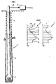
- FIG. 1 diagrams the environment allowing the value of the wear criterion v or f (v) to be obtained, the function f corresponding to an additional processing of the parameter v, for example to present the results in a simple manner to the operator.
- the invention mainly requires knowledge of the two background parameters, weight on the tool (W) and torque on the tool (T).
- a weight sweep is carried out in stages on the tool.
- the scanning range and the number of steps must be sufficient.
- the duration of each weight step is determined by establishing a stabilized operating regime.
- the reference 1 represents a well drilled using a drilling tool of the tricone type 2 fixed to the end of a drill string 3.
- the weight and torque measurements exerted on the tool 2 can be transmitted to the surface, for example by the drilling fluid channel, or by any other means (electric cable, etc.) and to the computer 4 by a power line symbolized by the arrow 5.
- the computer supplies the operator with the value of the wear criterion according to the invention.
- FIG. 2 shows side by side an evolution curve 6 of the weight W acting on the tool as a function of the depth PR and a curve 7 of evolution of the torque T acting on the tool as a function of the PR depth.
- the depth scales PR of curves 6 and 7 are identical and correspond to each other.
- the weight and torque measurements exerted on the tool can be carried out in a manner known to those skilled in the art, for example using the method known as M.W.D. ("Measurement While Drilling").
- the variation of the weight exerted on the tool can be obtained in a conventional manner by supporting more or less the drill string from the surface.
- Parameter measurements are made as a function of depth and / or time. It is recommended to be able to perform at least five steps per test, which leads to an overall test duration of around fifteen minutes.
- FIG. 2 schematically represents a test comprising five stages.
- the level of the bearing 8 corresponds to the weight on the tool being drilled from which the operator decides to trigger the test.
- the test includes a reduction in the weight on the tool to arrive at level 9 and then an increase in four other levels, respectively 10, 11, 12 and 13 corresponding to an increase in weight on the tool.
- the first series of measurements carried out at the bottom of the well, at the level of the tool, on the torque and the weight corresponds to the beginning of the attack of the rock by the tool, that is to say that its wear can to be considered practically zero.
- the series of measurements made during the first test period is transmitted to the surface of the computer, which establishes from this data a portion of the curve representative of the variations in torque as a function of variations in weight.
- the computer then keeps in memory this curve corresponding to the test period.
- the operator triggers a new test period, causing a step change in the weight applied to the tool, the computer again receives a new series of measurements from which he can obtain the curve representative of the variations of T as a function of W.
- the measurements made at the bottom of the well may present some inaccuracies, it is therefore necessary, from these measurements, to determine an average curve, for example by the method of least squares, and to deduce therefrom the average concavity of this curve represented by the mean radius of curvature, or a quantity linked to this mean value. Then, the determination of the wear can be done, either by controlling the evolution of the average concavity according to the progress of the drilling, or by composing the average concavity with average concavities established during reference tests.
- this surface measurement can possibly be used in the context of the present invention.
- the characteristics of the formation crossed, of the tool, the values of the hydraulic conditions and of N can be taken into account to normalize the value of the parameter v and / or that of the criterion.
- the abscissa of FIG. 4 expresses the weight exerted on the tool in tonnes and the ordinate the torque exerted on the tool expressed in m.daN.
- Curve 18 is located between dimensions 1320 and 1347 m, curve 19 between dimensions 1460 and 1463.5 m and curve 20 between dimensions 1559 and 1566.5 m.
- the method according to the present invention makes it possible to avoid drilling with worn tools or to reassemble tools too early.
- the knowledge of the degree of wear of the tools that it allows plays a direct role in reducing the cost of drilling.
Landscapes
- Engineering & Computer Science (AREA)
- Life Sciences & Earth Sciences (AREA)
- Geology (AREA)
- Mining & Mineral Resources (AREA)
- Physics & Mathematics (AREA)
- Environmental & Geological Engineering (AREA)
- Fluid Mechanics (AREA)
- General Life Sciences & Earth Sciences (AREA)
- Geochemistry & Mineralogy (AREA)
- Mechanical Engineering (AREA)
- Earth Drilling (AREA)
- Investigating Strength Of Materials By Application Of Mechanical Stress (AREA)
Applications Claiming Priority (2)
| Application Number | Priority Date | Filing Date | Title |
|---|---|---|---|
| FR8712928A FR2620819B1 (fr) | 1987-09-17 | 1987-09-17 | Methode de determination de l'usure d'un trepan en cours de forage |
| FR8712928 | 1987-09-17 |
Publications (2)
| Publication Number | Publication Date |
|---|---|
| EP0308327A1 EP0308327A1 (fr) | 1989-03-22 |
| EP0308327B1 true EP0308327B1 (fr) | 1992-04-22 |
Family
ID=9355014
Family Applications (1)
| Application Number | Title | Priority Date | Filing Date |
|---|---|---|---|
| EP88402319A Expired - Lifetime EP0308327B1 (fr) | 1987-09-17 | 1988-09-14 | Méthode de détermination de l'usure d'organes de découpe d'un outil en cours de forage d'une formation rocheuse |
Country Status (7)
| Country | Link |
|---|---|
| US (1) | US4926686A (da) |
| EP (1) | EP0308327B1 (da) |
| CA (1) | CA1310753C (da) |
| DE (1) | DE3870374D1 (da) |
| DK (1) | DK509388A (da) |
| FR (1) | FR2620819B1 (da) |
| NO (1) | NO884098L (da) |
Families Citing this family (25)
| Publication number | Priority date | Publication date | Assignee | Title |
|---|---|---|---|---|
| US5679894A (en) * | 1993-05-12 | 1997-10-21 | Baker Hughes Incorporated | Apparatus and method for drilling boreholes |
| US6186248B1 (en) | 1995-12-12 | 2001-02-13 | Boart Longyear Company | Closed loop control system for diamond core drilling |
| US5794720A (en) * | 1996-03-25 | 1998-08-18 | Dresser Industries, Inc. | Method of assaying downhole occurrences and conditions |
| US6408953B1 (en) * | 1996-03-25 | 2002-06-25 | Halliburton Energy Services, Inc. | Method and system for predicting performance of a drilling system for a given formation |
| US7032689B2 (en) * | 1996-03-25 | 2006-04-25 | Halliburton Energy Services, Inc. | Method and system for predicting performance of a drilling system of a given formation |
| US6109368A (en) * | 1996-03-25 | 2000-08-29 | Dresser Industries, Inc. | Method and system for predicting performance of a drilling system for a given formation |
| US6612382B2 (en) * | 1996-03-25 | 2003-09-02 | Halliburton Energy Services, Inc. | Iterative drilling simulation process for enhanced economic decision making |
| US6353799B1 (en) | 1999-02-24 | 2002-03-05 | Baker Hughes Incorporated | Method and apparatus for determining potential interfacial severity for a formation |
| US6276465B1 (en) | 1999-02-24 | 2001-08-21 | Baker Hughes Incorporated | Method and apparatus for determining potential for drill bit performance |
| US6386297B1 (en) | 1999-02-24 | 2002-05-14 | Baker Hughes Incorporated | Method and apparatus for determining potential abrasivity in a wellbore |
| US6634441B2 (en) | 2000-08-21 | 2003-10-21 | Halliburton Energy Services, Inc. | System and method for detecting roller bit bearing wear through cessation of roller element rotation |
| US6631772B2 (en) | 2000-08-21 | 2003-10-14 | Halliburton Energy Services, Inc. | Roller bit rearing wear detection system and method |
| US6722450B2 (en) | 2000-11-07 | 2004-04-20 | Halliburton Energy Svcs. Inc. | Adaptive filter prediction method and system for detecting drill bit failure and signaling surface operator |
| US6817425B2 (en) | 2000-11-07 | 2004-11-16 | Halliburton Energy Serv Inc | Mean strain ratio analysis method and system for detecting drill bit failure and signaling surface operator |
| US6712160B1 (en) | 2000-11-07 | 2004-03-30 | Halliburton Energy Services Inc. | Leadless sub assembly for downhole detection system |
| US6648082B2 (en) | 2000-11-07 | 2003-11-18 | Halliburton Energy Services, Inc. | Differential sensor measurement method and apparatus to detect a drill bit failure and signal surface operator |
| US7357197B2 (en) | 2000-11-07 | 2008-04-15 | Halliburton Energy Services, Inc. | Method and apparatus for monitoring the condition of a downhole drill bit, and communicating the condition to the surface |
| US9051781B2 (en) | 2009-08-13 | 2015-06-09 | Smart Drilling And Completion, Inc. | Mud motor assembly |
| US9745799B2 (en) | 2001-08-19 | 2017-08-29 | Smart Drilling And Completion, Inc. | Mud motor assembly |
| US6684949B1 (en) | 2002-07-12 | 2004-02-03 | Schlumberger Technology Corporation | Drilling mechanics load cell sensor |
| JP4016796B2 (ja) * | 2002-10-22 | 2007-12-05 | オムロン株式会社 | 車載用撮像装置及びそれを用いた車両運転支援装置 |
| GB2413403B (en) | 2004-04-19 | 2008-01-09 | Halliburton Energy Serv Inc | Field synthesis system and method for optimizing drilling operations |
| WO2009075667A2 (en) * | 2007-11-30 | 2009-06-18 | Halliburton Energy Services | Method and system for predicting performance of a drilling system having multiple cutting structures |
| WO2010039342A1 (en) | 2008-10-03 | 2010-04-08 | Halliburton Energy Services Inc. | Method and system for predicting performance of a drilling system |
| BR112016007602A2 (pt) | 2013-11-08 | 2017-08-01 | Halliburton Energy Services Inc | método para predição de desgaste dinâmico e sistema para predição de desgaste dinâmico |
Family Cites Families (5)
| Publication number | Priority date | Publication date | Assignee | Title |
|---|---|---|---|---|
| US3782190A (en) * | 1972-08-03 | 1974-01-01 | Texaco Inc | Method and apparatus for rotary drill testing |
| US4064749A (en) * | 1976-11-11 | 1977-12-27 | Texaco Inc. | Method and system for determining formation porosity |
| GB8411361D0 (en) * | 1984-05-03 | 1984-06-06 | Schlumberger Cambridge Researc | Assessment of drilling conditions |
| GB8416708D0 (en) * | 1984-06-30 | 1984-08-01 | Prad Res & Dev Nv | Drilling motor |
| US4627276A (en) * | 1984-12-27 | 1986-12-09 | Schlumberger Technology Corporation | Method for measuring bit wear during drilling |
-
1987
- 1987-09-17 FR FR8712928A patent/FR2620819B1/fr not_active Expired - Fee Related
-
1988
- 1988-09-13 DK DK509388A patent/DK509388A/da not_active Application Discontinuation
- 1988-09-14 DE DE8888402319T patent/DE3870374D1/de not_active Expired - Lifetime
- 1988-09-14 EP EP88402319A patent/EP0308327B1/fr not_active Expired - Lifetime
- 1988-09-15 NO NO88884098A patent/NO884098L/no unknown
- 1988-09-16 CA CA000577576A patent/CA1310753C/fr not_active Expired - Lifetime
- 1988-09-19 US US07/246,192 patent/US4926686A/en not_active Expired - Fee Related
Also Published As
| Publication number | Publication date |
|---|---|
| FR2620819B1 (fr) | 1993-06-18 |
| US4926686A (en) | 1990-05-22 |
| DK509388A (da) | 1989-03-18 |
| NO884098L (no) | 1989-03-20 |
| CA1310753C (fr) | 1992-11-24 |
| DE3870374D1 (de) | 1992-05-27 |
| FR2620819A1 (fr) | 1989-03-24 |
| EP0308327A1 (fr) | 1989-03-22 |
| NO884098D0 (no) | 1988-09-15 |
| DK509388D0 (da) | 1988-09-13 |
Similar Documents
| Publication | Publication Date | Title |
|---|---|---|
| EP0308327B1 (fr) | Méthode de détermination de l'usure d'organes de découpe d'un outil en cours de forage d'une formation rocheuse | |
| EP0330558B1 (fr) | Méthode et dispositif de transmission de l'information par câble et par ondes de boue | |
| EP3074748B1 (fr) | Procédé et dispositif de détermination de l'usure d'une face de dépouille d'un outil de coupe | |
| CN1082128C (zh) | 测定地下钻头所做功的方法 | |
| FR2611804A1 (fr) | Procede de controle des operations de forage d'un puits | |
| FR2544377A1 (fr) | Appareil et procede pour detecter des problemes de pompe dans une unite de pompage de puits | |
| EP3647533A1 (fr) | Optimisation du forage d'un tunnelier en fonction d'interactions terrain/machine | |
| EP1046781A1 (fr) | Méthode et système de détection du déplacement longitudinal d'un outil de forage | |
| EP0816629B1 (fr) | Méthode et système d'estimation en temps reel d'au moins un paramètre lié au déplacement d'un outil de forage | |
| EP0995009B1 (fr) | Dispositif et methode de mesure du debit de deblais de forage | |
| FR3066224A1 (fr) | Procede et systeme pour forer un puits de forage et identifier une defaillance du trepan de forage par deconvolution des donnees de capteur | |
| CN114526054A (zh) | 钻头井下工况实时识别系统、方法及相关设备 | |
| EP1448304A1 (fr) | Procede d'evaluation du taux de remplissage d'un broyeur rotatif tubulaire et dispositif pour sa mise en oeuvre | |
| CN115018164B (zh) | 泥水平衡顶管施工沉降预测方法、系统、设备及存储介质 | |
| WO2009004166A1 (fr) | Sonde ultrasonique d'imagerie 3-d pour caracteriser une zone de terrain autour d'un forage | |
| FR2674284A1 (fr) | Sonde pour determiner notamment l'injectivite d'un puits petroflier et procede de mesures la mettant en óoeuvre. | |
| EP3655591B1 (fr) | Pénétromètre statique et procédé de mesure associé | |
| CA2933504C (fr) | Procede de detection d'un dysfonctionnement en forage | |
| EP2157277A1 (fr) | Dispositif pour la réalisation d'un puits dans un sol | |
| EP0887511B1 (fr) | Méthode et système de détection de la précession d'un élément d'une garniture de forage | |
| FR2986247A1 (fr) | Machine de forage pour la realisation de pieux comprenant une sonde penetrometrique | |
| FR2723447A1 (fr) | Procede et systeme de reconnaissance des terrains autour d'une machine d'excavation | |
| EP1229172B1 (fr) | Procédé et machine pour la réalisation de pieux forés en terrain dur | |
| FR3052483A1 (fr) | Aide a la conduite d'un tunnelier par correlation entre mesures effectuees sur le tunnelier et donnees issues de sondages depuis la surface | |
| WO2021053005A1 (en) | A method for determination of properties of cuttings from rock drilling |
Legal Events
| Date | Code | Title | Description |
|---|---|---|---|
| PUAI | Public reference made under article 153(3) epc to a published international application that has entered the european phase |
Free format text: ORIGINAL CODE: 0009012 |
|
| 17P | Request for examination filed |
Effective date: 19880922 |
|
| AK | Designated contracting states |
Kind code of ref document: A1 Designated state(s): DE FR GB IT NL |
|
| 17Q | First examination report despatched |
Effective date: 19900608 |
|
| ITF | It: translation for a ep patent filed | ||
| GRAA | (expected) grant |
Free format text: ORIGINAL CODE: 0009210 |
|
| AK | Designated contracting states |
Kind code of ref document: B1 Designated state(s): DE FR GB IT NL |
|
| REF | Corresponds to: |
Ref document number: 3870374 Country of ref document: DE Date of ref document: 19920527 |
|
| GBT | Gb: translation of ep patent filed (gb section 77(6)(a)/1977) | ||
| PLBE | No opposition filed within time limit |
Free format text: ORIGINAL CODE: 0009261 |
|
| STAA | Information on the status of an ep patent application or granted ep patent |
Free format text: STATUS: NO OPPOSITION FILED WITHIN TIME LIMIT |
|
| 26N | No opposition filed | ||
| PGFP | Annual fee paid to national office [announced via postgrant information from national office to epo] |
Ref country code: DE Payment date: 19931020 Year of fee payment: 6 |
|
| PGFP | Annual fee paid to national office [announced via postgrant information from national office to epo] |
Ref country code: NL Payment date: 19940930 Year of fee payment: 7 |
|
| PG25 | Lapsed in a contracting state [announced via postgrant information from national office to epo] |
Ref country code: DE Effective date: 19950601 |
|
| PG25 | Lapsed in a contracting state [announced via postgrant information from national office to epo] |
Ref country code: NL Effective date: 19960401 |
|
| NLV4 | Nl: lapsed or anulled due to non-payment of the annual fee |
Effective date: 19960401 |
|
| PGFP | Annual fee paid to national office [announced via postgrant information from national office to epo] |
Ref country code: FR Payment date: 19960712 Year of fee payment: 9 |
|
| PGFP | Annual fee paid to national office [announced via postgrant information from national office to epo] |
Ref country code: GB Payment date: 19960819 Year of fee payment: 9 |
|
| PG25 | Lapsed in a contracting state [announced via postgrant information from national office to epo] |
Ref country code: GB Free format text: LAPSE BECAUSE OF NON-PAYMENT OF DUE FEES Effective date: 19970914 |
|
| PG25 | Lapsed in a contracting state [announced via postgrant information from national office to epo] |
Ref country code: FR Free format text: THE PATENT HAS BEEN ANNULLED BY A DECISION OF A NATIONAL AUTHORITY Effective date: 19970930 |
|
| GBPC | Gb: european patent ceased through non-payment of renewal fee |
Effective date: 19970914 |
|
| REG | Reference to a national code |
Ref country code: FR Ref legal event code: ST |
|
| PG25 | Lapsed in a contracting state [announced via postgrant information from national office to epo] |
Ref country code: IT Free format text: LAPSE BECAUSE OF NON-PAYMENT OF DUE FEES;WARNING: LAPSES OF ITALIAN PATENTS WITH EFFECTIVE DATE BEFORE 2007 MAY HAVE OCCURRED AT ANY TIME BEFORE 2007. THE CORRECT EFFECTIVE DATE MAY BE DIFFERENT FROM THE ONE RECORDED. Effective date: 20050914 |