EP0308083A2 - Vorrichtung und Verfahren zum Entnehmen von Bodenproben und zum Aufbewahren von flüchtigen Elementen die sich darin befinden - Google Patents
Vorrichtung und Verfahren zum Entnehmen von Bodenproben und zum Aufbewahren von flüchtigen Elementen die sich darin befinden Download PDFInfo
- Publication number
- EP0308083A2 EP0308083A2 EP88307786A EP88307786A EP0308083A2 EP 0308083 A2 EP0308083 A2 EP 0308083A2 EP 88307786 A EP88307786 A EP 88307786A EP 88307786 A EP88307786 A EP 88307786A EP 0308083 A2 EP0308083 A2 EP 0308083A2
- Authority
- EP
- European Patent Office
- Prior art keywords
- soil
- sample
- casing
- annulus
- sampling
- Prior art date
- Legal status (The legal status is an assumption and is not a legal conclusion. Google has not performed a legal analysis and makes no representation as to the accuracy of the status listed.)
- Withdrawn
Links
Images


Classifications
-
- G—PHYSICS
- G01—MEASURING; TESTING
- G01N—INVESTIGATING OR ANALYSING MATERIALS BY DETERMINING THEIR CHEMICAL OR PHYSICAL PROPERTIES
- G01N1/00—Sampling; Preparing specimens for investigation
-
- E—FIXED CONSTRUCTIONS
- E21—EARTH OR ROCK DRILLING; MINING
- E21B—EARTH OR ROCK DRILLING; OBTAINING OIL, GAS, WATER, SOLUBLE OR MELTABLE MATERIALS OR A SLURRY OF MINERALS FROM WELLS
- E21B49/00—Testing the nature of borehole walls; Formation testing; Methods or apparatus for obtaining samples of soil or well fluids, specially adapted to earth drilling or wells
- E21B49/02—Testing the nature of borehole walls; Formation testing; Methods or apparatus for obtaining samples of soil or well fluids, specially adapted to earth drilling or wells by mechanically taking samples of the soil
-
- E—FIXED CONSTRUCTIONS
- E21—EARTH OR ROCK DRILLING; MINING
- E21B—EARTH OR ROCK DRILLING; OBTAINING OIL, GAS, WATER, SOLUBLE OR MELTABLE MATERIALS OR A SLURRY OF MINERALS FROM WELLS
- E21B10/00—Drill bits
- E21B10/02—Core bits
- E21B10/04—Core bits with core destroying means
-
- E—FIXED CONSTRUCTIONS
- E21—EARTH OR ROCK DRILLING; MINING
- E21B—EARTH OR ROCK DRILLING; OBTAINING OIL, GAS, WATER, SOLUBLE OR MELTABLE MATERIALS OR A SLURRY OF MINERALS FROM WELLS
- E21B25/00—Apparatus for obtaining or removing undisturbed cores, e.g. core barrels or core extractors
- E21B25/08—Coating, freezing, consolidating cores; Recovering uncontaminated cores or cores at formation pressure
-
- E—FIXED CONSTRUCTIONS
- E21—EARTH OR ROCK DRILLING; MINING
- E21B—EARTH OR ROCK DRILLING; OBTAINING OIL, GAS, WATER, SOLUBLE OR MELTABLE MATERIALS OR A SLURRY OF MINERALS FROM WELLS
- E21B49/00—Testing the nature of borehole walls; Formation testing; Methods or apparatus for obtaining samples of soil or well fluids, specially adapted to earth drilling or wells
- E21B49/005—Testing the nature of borehole walls or the formation by using drilling mud or cutting data
-
- E—FIXED CONSTRUCTIONS
- E21—EARTH OR ROCK DRILLING; MINING
- E21B—EARTH OR ROCK DRILLING; OBTAINING OIL, GAS, WATER, SOLUBLE OR MELTABLE MATERIALS OR A SLURRY OF MINERALS FROM WELLS
- E21B7/00—Special methods or apparatus for drilling
- E21B7/002—Drilling with diversely driven shafts extending into the borehole
-
- E—FIXED CONSTRUCTIONS
- E21—EARTH OR ROCK DRILLING; MINING
- E21B—EARTH OR ROCK DRILLING; OBTAINING OIL, GAS, WATER, SOLUBLE OR MELTABLE MATERIALS OR A SLURRY OF MINERALS FROM WELLS
- E21B21/00—Methods or apparatus for flushing boreholes, e.g. by use of exhaust air from motor
- E21B21/01—Arrangements for handling drilling fluids or cuttings outside the borehole, e.g. mud boxes
Definitions
- Prior known soil sampling techniques and devices are capable of removing an essentially undisturbed sample of soil from a subterranean location for the usual purpose of running compaction tests and the like in advance of a construction project or for characterizing contaminants in the soil.
- Such devices suffer from two disadvantages in that, first, they have no means for continuously removing soil from above the sampler as drilling progresses, and, secondly, known apparatus for taking samples is generally incapable of retaining volatile components in the sample during removal of the sample to the surface and while the sample is removed from the sampler at the surface.
- the present invention accordingly provides a soil sampling device comprising a tubular casing, a tubular sampling section connected to the lower and of said casing for collecting an undisturbed sample of soil from a subsurface location, means for inserting said casing and said sampling section into the soil to the subsurface location prior to removal of a soil sample therefrom, cutter means in said casing disposed above the undisturbed sample to be taken for continuously cutting soil from the upper surface of said sample as said casing and sampling section are driven into the soil and means for removing the unwanted cut soil from above the undisturbed sample.
- the preferred embodiment comprises a subterranean soil sampling device which cleanly penetrates the soil while continuously removing the undesirable portion of the soil above the sampling device and which removes an undisturbed soil sample with all contaminant fractions therein, including volatile components so that the sample can be analyzed at a surface test facility to provide an accurate indication of the types and concentration of contaminants present.
- the present invention further provides a method of sampling of soil to determine the location, identity and concentration of contaminants therein comprising the steps of:
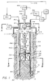
- the soil sampling device is comprised of a rotatable tubular sampler section 10 having a sharpened lower cutting edge 12.
- the vertical length of the sampler section 10 is preferably selected such that the sample S to be tested will be sandwiched between cover layers of soil of sufficient thickness at both the top and bottom ends of the sampler section 10 so that the cover layers will effectively seal and prevent the sample S from loss of any volatile contaminants through exposed upper and lower surfaces.
- Removably affixed to the upper end of sampler section 10 is an adapter connector 14 which in turn is connected to casing sections 16.
- a casing cap 18 is provided to effectively pressure seal the interior of the casing.
- the casing sections 16, adapter connector 14 and sampler section 10 are rotatably driven together by a surface located casing drive motor 24 shown schematically.
- the device disclosed herein can be mounted on a standard drilling rig, not shown.
- a rotatable cutter 28 comprised of a rotatable blade 32 for removing soil from above the undisturbed sample S.
- Blade 32 is drivingly affixed to a vertically extending drive rod 34 which in turn is driven by a surface located cutter blade drive motor 36 shown schematically.
- a bearing support 40 is provided in the casing 16 at the adapter connector 14 above the cutter 28 to keep the cutter blade 32 centrally disposed in the casing.
- Cuttings produced by the rotating cutter blade 32 are discharged from the cutting surface radially outwardly from the cutter 28 through discharge ports 44 through the walls of casing 16 into an annulus 46 between the outer casing wall and the edge 54 of the borehole.
- This annulus 46 is created by an annulus cutter blade 50 rigidly affixed to the lower end of the sampler section 10 and rotatable therewith under the influence of the casing drive motor 24.
- a source 56 of high pressure fluid which may comprise hot or ambient temperature air or steam is preferably provided for the purpose of flushing the annulus 46 of cuttings created both by the annulus cutter 50 and by the central cutter blade 32.
- Hot air or steam may be chosen as desired by the operator if the presense of volatilizable contaminants is suspected or detected.
- a conduit 58 is provided which extends downwardly from the source 56 of high pressure fluid to a discharge location having a plurality of circumfrentially spaced upwardly directed discharge jets 62 located slightly above the upper surface of annulus cutter blade 50.
- high pressure fluid can be discharged continuously or periodically as desired by the operator to upwardly flush the cuttings and any volatile contaminant fractions present through the annulus 46.
- the fluid supply conduit 58 extends from the fluid supply source 56 to a centrally located swivel connector 66 which is mounted on the cutter drive rod 34 above the cutter blade drive motor 36. High pressure fluid is thus permitted to enter a downwardly extending passageway 68 provided for this purpose in the cutter drive rod 34.
- This passageway 68 continues downwardly and is in fluid communication with a plurality of vertically spaced swivels 74a - 74d mounted on the cutter drive rod 34 below the casing cap 18.
- a non-rotatable generally horizontally extending conduit 59 is provided in fluid communication with each of the swivels 74 for transmitting high pressure fluid generally radially from the cutter blade drive rod passageway 68 to vertically extending continuations 60 of the fluid conduit affixed to the casing 16 and movable therewith. These in turn are placed into fluid communication with the upwardly directed jets 62 above the annulus cutter 50.
- a gas containment hood 64 is provided at the ground surface in sealing engagement therewith and in sealing engagement with the outer wall of the casing so that volatile contaminants liberated from the downhole sampling and cutting are retained in the hood 64 and are thus prevented from escaping to atmosphere.
- a particularly important feature of the invention comprises the provision of means for cryogenically cooling or freezing of the undisturbed soil sample S at the subsurface location so that volatile components in the sample S will not be lost during removal of the sample from the subsurface location nor lost during removal of the sample from the sampler section 10.
- a thermally insulating jacket 80 is provided which substantially surrounds the exterior of the sampler section 10.
- a source 82 of cold fluid, preferably liquid nitrogen, is provided at the surface and is connected when desired via a quick disconnect coupling 84 to a downwardly extending coolant feed line 88 which extends in the annulus outside of the casing 16 and which at its lower end is attached to the thermally insulating jacket 80.
- jacket 80 may comprise a continuous spiral coil of coolant conduit extending around the periphery of the sampler section 10 and in heat transfer relationship therewith.
- FIG. 4 An alternative form of sample cooling means is shown in Fig. 4 which, instead of a jacket, comprises a centrally disposed pointed probe 90 intended to cool the soil sample S from the inside out rather than from the outside in
- the source 82 of cooling liquid is conducted downwardly through a vertically extending passageway 92 in the cutter blade drive rod 34 specially provided for this purpose.
- Expendable inert coolant liquid is then discharged through apertures 96 in the probe 90 to cool the sample S.
- a slightly modified swivel 66A like swivel 66, can be used for connecting the air supply source to the passageway 92 in the drive rod and also for use as the connection to the liquid coolant source 82.
- a separate quick disconnect coupling 84 will then be provided for easily connecting or disconnecting the liquid coolant source 82 which is not in use during boring.
- Spent liquid coolant or vapor from the jacket 80 may, if desired, be returned to the surface for recovery or analysis.
- Spent fluid may be analyzed if desired in monitor 100 or is bypassed directly to a holding tank 102 which in turn is connected by a return line 104 to the source 82 of cold fluid.
- Spent vapors may be discharged to atmosphere provided that the coolant is non -toxic.
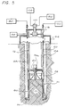
- FIG. 5 An alternative embodiment of the invention is shown in Fig. 5 and employs a pressurized casing 16 sealed be casing cap 18 and a cutter drive motor 36A located downhole in the pressurized casing 16. Since there is no cutter blade drive rod which extends to the surface as in the embodiment of the invention shown in Figs. 1-3 and 4, means must be provided for supplying pressurized motive fluid to the downhole cutter drive motor 36A.
- a second source 106 of high pressure air typically at higher pressure than that which is required of the first source 56 used to flush the cuttings from the annulus 46, is provided at the surface and is placed in fluid communication with the interior of the casing 16 by a swivel 107 which extends through casing cap 18.
- FIG. 5 embodiment are similar to those shown in Fig. 1 and like reference numerals have therefore been used to designate the same components.
- Use of a down hole cutter drive motor 36A may be preferred in some instances to the use of a long cutter drive rod extending from the surface to the downhole location at which the sample is to be taken.
- the sample remover 110 shown in Fig. 6 is attachable by fastening pins 114 or the like to the lower end of the casing 16 after it has been removed from the ground.
- the remover 110 comprises a frame 116 which may include a cylindrical wall section 118 and an annular base 120 integral therewith.
- An annular split sample cutter removal mold 130 having a flat supporting base 132 and a sharpened, preferably sawtooth leading edge 134 is centrally mounted for longitudinal movement in the frame 116.
- a worm gear 136 centrally extending through a worm gear bearing 138 in the base 120 of the frame 116 is non-rotatably connected to the supporting base so that the removal mold 130 rotates about its longitudinal axis as the worm gear 136 rotates under power imparted thereto by a motor 140 or a hand crank 142 shown schematically.
- the sampler section 10 and attached adapter and casing sections 14, 16 are rotatably driven into the soil to the desired depth of the sample S to be taken.
- the centrally disposed cutter 28 is rotated and driven into the soil such that the cutter blade 32 continuously cuts and removes unwanted soil from immediately above the level of the sampler section 10.
- the cuttings are radially discharged through the discharge ports 44 and thence upwardly through the annulus 46 created by annulus cutter 50 to surface disposal. Fluid from the high pressure source 56 is used as necessary to assist in the removal of the cuttings.
- Means may be provided for sampling the gases collected in the containment hood 64 to determine the presence and concentration of preselected volatile contaminants therein.
- the sampled gases may then be scrubbed to remove contaminants to a safe level and the remaining cleansed gases discharged to atmosphere. It is particularly contemplated that the operator will use steam or heated air as the source of high pressure fluid to be emitted from the annulus cutter jets 62 whenever the presence of volatile contaminants is suspected or sensed in the collected gases in the containment hood 64 since heated fluid will liberate a greater proportion of the volatile contaminants which the operator wishes to detect than would be liberated by unheated fluid.
- the operator may be signaled to take a soil sample in which the volatiles are retained and which then may be subjected to a more rigorous analysis at the surface with the results being compared With the results of the sensing of the volatile contaminants from the gases collected in the hood 64. All of this collected data may then be correlated with vertical and horizontal position data and used to prepare detailed two or three dimensional mapping of the sampled area.
- disconnect couplings 84 are attached to the coolant source 82 and the sample S is rapidly chilled by introducing cooling fluid to the jacket 80 and/or the central cooling probe 90. The centrally disposed cutter assembly is subsequently removed. Continuous circulation of cooling liquid is maintained during this time. Finally the casing sections 16 and attached adapter connector 14 and sampler section 10 with the undisturbed sample S therein are removed to the surface where the sample is quickly removed by the removal device 110 so that the sample may then be safely transported in a freeze box or the like to a laboratory for testing and without loss of volatile components.
Landscapes
- Life Sciences & Earth Sciences (AREA)
- Engineering & Computer Science (AREA)
- Geology (AREA)
- Mining & Mineral Resources (AREA)
- Physics & Mathematics (AREA)
- Environmental & Geological Engineering (AREA)
- Fluid Mechanics (AREA)
- General Life Sciences & Earth Sciences (AREA)
- Geochemistry & Mineralogy (AREA)
- Mechanical Engineering (AREA)
- Soil Sciences (AREA)
- Health & Medical Sciences (AREA)
- Chemical & Material Sciences (AREA)
- Analytical Chemistry (AREA)
- Biochemistry (AREA)
- General Health & Medical Sciences (AREA)
- General Physics & Mathematics (AREA)
- Immunology (AREA)
- Pathology (AREA)
- Sampling And Sample Adjustment (AREA)
- Investigation Of Foundation Soil And Reinforcement Of Foundation Soil By Compacting Or Drainage (AREA)
Applications Claiming Priority (2)
| Application Number | Priority Date | Filing Date | Title |
|---|---|---|---|
| US07/093,305 US4809790A (en) | 1987-09-04 | 1987-09-04 | Device for sampling soils and retaining volatiles therein and method of using same |
| US93305 | 1987-09-04 |
Publications (2)
| Publication Number | Publication Date |
|---|---|
| EP0308083A2 true EP0308083A2 (de) | 1989-03-22 |
| EP0308083A3 EP0308083A3 (de) | 1989-06-14 |
Family
ID=22238221
Family Applications (1)
| Application Number | Title | Priority Date | Filing Date |
|---|---|---|---|
| EP88307786A Withdrawn EP0308083A3 (de) | 1987-09-04 | 1988-08-23 | Vorrichtung und Verfahren zum Entnehmen von Bodenproben und zum Aufbewahren von flüchtigen Elementen die sich darin befinden |
Country Status (6)
| Country | Link |
|---|---|
| US (1) | US4809790A (de) |
| EP (1) | EP0308083A3 (de) |
| JP (1) | JPS6471992A (de) |
| KR (1) | KR890005506A (de) |
| AU (1) | AU602789B2 (de) |
| NZ (1) | NZ225776A (de) |
Cited By (4)
| Publication number | Priority date | Publication date | Assignee | Title |
|---|---|---|---|---|
| EP0893570A1 (de) * | 1997-07-11 | 1999-01-27 | Mait - S.p.A. | Mehrfachbohrkopfeinheit für lockeren Untergrund |
| EP0855490A3 (de) * | 1997-01-24 | 2000-03-29 | Bauer Spezialtiefbau GmbH | Bohrvorrichtung und Drehmomentstütze für eine Bohrvorrichtung |
| CN104458317A (zh) * | 2014-09-19 | 2015-03-25 | 航天东方红卫星有限公司 | 微弱引力天体岩石骤冷采样方法 |
| CN109115545A (zh) * | 2018-08-03 | 2019-01-01 | 邹城兖矿泰德工贸有限公司 | 地质套管 |
Families Citing this family (33)
| Publication number | Priority date | Publication date | Assignee | Title |
|---|---|---|---|---|
| US5135058A (en) * | 1990-04-26 | 1992-08-04 | Millgard Environmental Corporation | Crane-mounted drill and method for in-situ treatment of contaminated soil |
| US5104525A (en) * | 1991-05-13 | 1992-04-14 | Roderick James R | Portable self-contained water remediation package |
| US5979569A (en) * | 1993-09-21 | 1999-11-09 | Simulprobe Technologies, Inc. | Method and apparatus for environmental sampling |
| US5421419A (en) * | 1993-09-21 | 1995-06-06 | Simulprobe Technologies, Inc. | Method and apparatus for fluid and soil sampling |
| US5743343A (en) * | 1993-09-21 | 1998-04-28 | Simulprobe Technologies, Inc. | Method and apparatus for fluid and soil sampling |
| US5474140A (en) * | 1994-10-31 | 1995-12-12 | Stevens; Jim A. | Soil sampling probe |
| US6098724A (en) * | 1997-12-01 | 2000-08-08 | U.S. Oil Company, Incorporated | Soil sample procuring tool and associated method of testing the soil sample |
| US6591702B2 (en) * | 2000-12-04 | 2003-07-15 | Gas Technology Institute | Method for identifying sources of rapidly released contaminants at contaminated sites |
| AU2002244190A1 (en) * | 2001-02-26 | 2002-09-12 | Diedrich Drill, Inc. | Sonic drill head |
| US6597992B2 (en) | 2001-11-01 | 2003-07-22 | Soil And Topography Information, Llc | Soil and topography surveying |
| WO2004027677A1 (en) * | 2002-09-23 | 2004-04-01 | Columbia Technologies, Llc | System, method and computer program product for subsurface contamination detection and analysis |
| US7100707B2 (en) * | 2004-01-16 | 2006-09-05 | Harold Howard | Stabilized soil core samples and method for preparing same |
| US7677330B2 (en) * | 2007-02-14 | 2010-03-16 | Peter Hammond | Apparatus for in situ testing of a soil sample |
| US7644610B2 (en) * | 2007-08-24 | 2010-01-12 | Baker Hughes Incorporated | Automated formation fluid clean-up to sampling switchover |
| KR200459759Y1 (ko) * | 2009-12-07 | 2012-06-12 | 대한민국 | 전단시험기용 토양 채취기 |
| KR101179070B1 (ko) | 2010-12-17 | 2012-09-03 | 한국지질자원연구원 | 오염 토양에서 채취된 시료의 대표성 검증 방법 |
| US8851203B2 (en) | 2011-04-08 | 2014-10-07 | Layne Christensen Company | Sonic drill head |
| CN103939143B (zh) * | 2014-04-17 | 2015-12-30 | 中国矿业大学 | 煤层巷道破碎带影响范围的测定方法及其装置 |
| DK3143240T3 (da) * | 2014-05-16 | 2019-07-29 | Aarbakke Innovation A S | Rørformet multifunktionspenetreringsredskab til brøndboring |
| WO2017130557A1 (ja) * | 2016-01-27 | 2017-08-03 | ハイテック株式会社 | 地下水の検出方法、ボーリング装置およびコア採取装置 |
| CN106769240B (zh) * | 2016-12-16 | 2019-04-23 | 重庆大学 | 一种自动补冷的液氮制冷式煤瓦斯取样器 |
| CN106761393B (zh) * | 2017-01-19 | 2018-11-06 | 中国矿业大学(北京) | 一种特种空间气液循环钻进方法和装置 |
| US11053763B2 (en) | 2018-07-03 | 2021-07-06 | Halliburton Energy Services, Inc. | Method and apparatus for pinching control lines |
| US11573156B2 (en) * | 2019-01-15 | 2023-02-07 | Westinghouse Electric Company Llc | Minimally invasive microsampler for intact removal of surface deposits and substrates |
| CN110068478B (zh) * | 2019-05-13 | 2020-01-03 | 长安大学 | 一种基于不扰动土探井取样机器人的探井取样方法 |
| CN110567756B (zh) * | 2019-10-10 | 2022-08-02 | 上海格林曼环境技术有限公司 | 一种用于原位热修复场地的土壤热采样方法 |
| US11549315B2 (en) | 2020-06-26 | 2023-01-10 | Aarbakke Innovation As | Method for separating nested well tubulars in gravity contact with each other |
| CN113984490A (zh) * | 2021-08-26 | 2022-01-28 | 四川航天系统工程研究所 | 利用侵彻生热诱导分析地外天体土壤挥发分的系统及方法 |
| CN114295805B (zh) * | 2021-12-06 | 2022-06-24 | 生态环境部南京环境科学研究所 | 一种模拟土壤有机污染物在土壤中迁移转化的装置 |
| CN118794728A (zh) * | 2022-06-30 | 2024-10-18 | 中国地质科学院郑州矿产综合利用研究所 | 一种车载单孔多点式防挥发土样采集装置 |
| CN115127868B (zh) * | 2022-08-31 | 2023-04-28 | 江苏汉鼎汉方环境科技有限公司 | 一种用于环境监测的取样装置 |
| CN116301094B (zh) * | 2022-12-08 | 2025-09-19 | 哈尔滨工业大学 | 一种月壤水冰模拟物的温度控制保持装置、力载测试装置及方法 |
| CN116558876B (zh) * | 2023-07-12 | 2023-09-08 | 北京建工环境修复股份有限公司 | 一种便于携带的土壤修复用采样装置 |
Family Cites Families (19)
| Publication number | Priority date | Publication date | Assignee | Title |
|---|---|---|---|---|
| US2514586A (en) * | 1946-10-25 | 1950-07-11 | Lester Callahan | Apparatus for drilling wells |
| US2626780A (en) * | 1951-06-06 | 1953-01-27 | Standard Oil Dev Co | Double-acting drill bit |
| US2779195A (en) * | 1952-04-10 | 1957-01-29 | Simon Karl | Device for subsoil testing and taking of specimens |
| US2812160A (en) * | 1953-06-30 | 1957-11-05 | Exxon Research Engineering Co | Recovery of uncontaminated cores |
| US2854219A (en) * | 1954-11-22 | 1958-09-30 | Alvin S Macneil | Apparatus for deep well drilling |
| US2915285A (en) * | 1956-05-23 | 1959-12-01 | Jersey Prod Res Co | Coring subterranean formations |
| US2975849A (en) * | 1958-04-25 | 1961-03-21 | Diamond Oil Well Drilling | Core disintegrating drill bit |
| FR1240063A (fr) * | 1959-07-23 | 1960-09-02 | Perfectionnements aux têtes de mèches de forage | |
| US3055443A (en) * | 1960-05-31 | 1962-09-25 | Jersey Prod Res Co | Drill bit |
| DE1171848B (de) * | 1960-06-09 | 1964-06-11 | Bade & Co Gmbh | Vorrichtung und Verfahren zum Niederbringen eines Bohrloches |
| US3318394A (en) * | 1965-02-19 | 1967-05-09 | Univ Michigan Central | Method and apparatus for obtaining soil samples |
| FR1478619A (fr) * | 1966-03-17 | 1967-04-28 | Aquitaine Petrole | Outil pour la destruction des carottes |
| US3416374A (en) * | 1967-04-24 | 1968-12-17 | Colen S. Smith | Sampling device |
| US3552505A (en) * | 1968-11-22 | 1971-01-05 | American Coldset Corp | Core bit and core crusher apparatus |
| FR2408693A1 (fr) * | 1977-11-15 | 1979-06-08 | Causse Antoine | Outil de carottage a clapets pour le creusement de trous dans le sol |
| US4345484A (en) * | 1980-10-14 | 1982-08-24 | Gregory Gould | Sampling device |
| DE3114612C2 (de) * | 1981-04-07 | 1983-11-10 | Hochstrasser, Jürgen, 6600 Saarbrücken | Bohrvorrichtung für Hartgestein |
| FR2535781B1 (fr) * | 1982-11-09 | 1985-08-09 | Rech Geolog Miniere | Procede et appareil pour la traversee rapide de terrains ininteressants, au cours d'un forage de recherches minieres |
| GB2154630B (en) * | 1984-02-24 | 1986-09-17 | Matsuzawa Kiko Kabushiki Kaish | Construction method for foundation piling |
-
1987
- 1987-09-04 US US07/093,305 patent/US4809790A/en not_active Expired - Fee Related
-
1988
- 1988-08-10 NZ NZ225776A patent/NZ225776A/xx unknown
- 1988-08-23 EP EP88307786A patent/EP0308083A3/de not_active Withdrawn
- 1988-09-02 AU AU21815/88A patent/AU602789B2/en not_active Expired - Fee Related
- 1988-09-03 KR KR1019880011421A patent/KR890005506A/ko not_active Withdrawn
- 1988-09-05 JP JP63220601A patent/JPS6471992A/ja active Pending
Cited By (5)
| Publication number | Priority date | Publication date | Assignee | Title |
|---|---|---|---|---|
| EP0855490A3 (de) * | 1997-01-24 | 2000-03-29 | Bauer Spezialtiefbau GmbH | Bohrvorrichtung und Drehmomentstütze für eine Bohrvorrichtung |
| EP0893570A1 (de) * | 1997-07-11 | 1999-01-27 | Mait - S.p.A. | Mehrfachbohrkopfeinheit für lockeren Untergrund |
| CN104458317A (zh) * | 2014-09-19 | 2015-03-25 | 航天东方红卫星有限公司 | 微弱引力天体岩石骤冷采样方法 |
| CN104458317B (zh) * | 2014-09-19 | 2017-04-19 | 航天东方红卫星有限公司 | 微弱引力天体岩石骤冷采样方法 |
| CN109115545A (zh) * | 2018-08-03 | 2019-01-01 | 邹城兖矿泰德工贸有限公司 | 地质套管 |
Also Published As
| Publication number | Publication date |
|---|---|
| JPS6471992A (en) | 1989-03-16 |
| NZ225776A (en) | 1989-12-21 |
| US4809790A (en) | 1989-03-07 |
| AU602789B2 (en) | 1990-10-25 |
| EP0308083A3 (de) | 1989-06-14 |
| KR890005506A (ko) | 1989-05-15 |
| AU2181588A (en) | 1989-03-09 |
Similar Documents
| Publication | Publication Date | Title |
|---|---|---|
| US4809790A (en) | Device for sampling soils and retaining volatiles therein and method of using same | |
| US5435176A (en) | Hazardous waste characterizer and remediation method and system | |
| US4834194A (en) | Method and apparatus for detection of volatile soil contaminants in situ | |
| US5201219A (en) | Method and apparatus for measuring free hydrocarbons and hydrocarbons potential from whole core | |
| EP0581976B1 (de) | Bodengasprobennehmer | |
| US8904857B2 (en) | Downhole sampling | |
| US10309177B2 (en) | Cryogenic core collection | |
| US5447052A (en) | Microwave hydrocarbon gas extraction system | |
| CA2833576C (en) | Sampling and evaluation of subterranean formation fluid | |
| DK154529B (da) | Fremgangsmaade til bestemmelse af olieegenskaber hos geologiske sedimenter paa basis af mindre proeveudtagninger | |
| EP0543944A1 (de) | Verfahren und gerät zum entnehmen und analysieren von porengas-/porenflüssigkeitsproben aus unterirdischen formationen von bestimmter tiefe. | |
| MX2007011470A (es) | Metodo y aparato para el muestreo de fluidos de una formacion. | |
| EP1620631B1 (de) | Aufzeichnungsvorrichtung für kontinuierliche daten für einen bohrlochprobenbehälter | |
| MX2007009018A (es) | Metodos y aparato para monitorear los niveles de contaminacion en un fluido de formacion. | |
| NO321922B1 (no) | Anordning og fremgangsmate for nedihulls analyse av en grunnformasjons-fluidprove i et borehull | |
| US11761942B2 (en) | System and method for environmental sampling and analysis | |
| US5036916A (en) | Method and apparatus for locating wet cement plugs in open bore holes | |
| US5673762A (en) | Expendable protective sleeve and method of use for soil and groundwater sampling | |
| CN110567756B (zh) | 一种用于原位热修复场地的土壤热采样方法 | |
| US20080236822A1 (en) | System and method for separating, monitoring and sampling coiled tubing flow back returns | |
| US3857289A (en) | Soil sampling auger | |
| US3221558A (en) | Sampling method and apparatus | |
| CN111257042A (zh) | 土壤热采样用冷却装置、土壤热采样系统及采样方法 | |
| CN222812607U (zh) | 一种土壤耕层深度测量装置 | |
| Harrison et al. | A probe method for soil water sampling and subsurface measurements |
Legal Events
| Date | Code | Title | Description |
|---|---|---|---|
| PUAI | Public reference made under article 153(3) epc to a published international application that has entered the european phase |
Free format text: ORIGINAL CODE: 0009012 |
|
| AK | Designated contracting states |
Kind code of ref document: A2 Designated state(s): AT BE CH DE ES FR GB GR IT LI NL SE |
|
| PUAL | Search report despatched |
Free format text: ORIGINAL CODE: 0009013 |
|
| AK | Designated contracting states |
Kind code of ref document: A3 Designated state(s): AT BE CH DE ES FR GB GR IT LI NL SE |
|
| 17P | Request for examination filed |
Effective date: 19891212 |
|
| RAP1 | Party data changed (applicant data changed or rights of an application transferred) |
Owner name: MANCHAK, FRANK, JR. |
|
| 17Q | First examination report despatched |
Effective date: 19900612 |
|
| STAA | Information on the status of an ep patent application or granted ep patent |
Free format text: STATUS: THE APPLICATION IS DEEMED TO BE WITHDRAWN |
|
| 18D | Application deemed to be withdrawn |
Effective date: 19910410 |