EP0308027A2 - Dichteregelung einer Suspension unter Verwendung einer Strahlungsquelle - Google Patents
Dichteregelung einer Suspension unter Verwendung einer Strahlungsquelle Download PDFInfo
- Publication number
- EP0308027A2 EP0308027A2 EP88202000A EP88202000A EP0308027A2 EP 0308027 A2 EP0308027 A2 EP 0308027A2 EP 88202000 A EP88202000 A EP 88202000A EP 88202000 A EP88202000 A EP 88202000A EP 0308027 A2 EP0308027 A2 EP 0308027A2
- Authority
- EP
- European Patent Office
- Prior art keywords
- mixture
- radiation
- suspension density
- source
- detector
- Prior art date
- Legal status (The legal status is an assumption and is not a legal conclusion. Google has not performed a legal analysis and makes no representation as to the accuracy of the status listed.)
- Granted
Links
Images
Classifications
-
- B—PERFORMING OPERATIONS; TRANSPORTING
- B01—PHYSICAL OR CHEMICAL PROCESSES OR APPARATUS IN GENERAL
- B01J—CHEMICAL OR PHYSICAL PROCESSES, e.g. CATALYSIS OR COLLOID CHEMISTRY; THEIR RELEVANT APPARATUS
- B01J8/00—Chemical or physical processes in general, conducted in the presence of fluids and solid particles; Apparatus for such processes
- B01J8/18—Chemical or physical processes in general, conducted in the presence of fluids and solid particles; Apparatus for such processes with fluidised particles
- B01J8/1809—Controlling processes
-
- C—CHEMISTRY; METALLURGY
- C10—PETROLEUM, GAS OR COKE INDUSTRIES; TECHNICAL GASES CONTAINING CARBON MONOXIDE; FUELS; LUBRICANTS; PEAT
- C10J—PRODUCTION OF PRODUCER GAS, WATER-GAS, SYNTHESIS GAS FROM SOLID CARBONACEOUS MATERIAL, OR MIXTURES CONTAINING THESE GASES; CARBURETTING AIR OR OTHER GASES
- C10J3/00—Production of combustible gases containing carbon monoxide from solid carbonaceous fuels
- C10J3/46—Gasification of granular or pulverulent flues in suspension
- C10J3/48—Apparatus; Plants
- C10J3/50—Fuel charging devices
-
- C—CHEMISTRY; METALLURGY
- C10—PETROLEUM, GAS OR COKE INDUSTRIES; TECHNICAL GASES CONTAINING CARBON MONOXIDE; FUELS; LUBRICANTS; PEAT
- C10J—PRODUCTION OF PRODUCER GAS, WATER-GAS, SYNTHESIS GAS FROM SOLID CARBONACEOUS MATERIAL, OR MIXTURES CONTAINING THESE GASES; CARBURETTING AIR OR OTHER GASES
- C10J3/00—Production of combustible gases containing carbon monoxide from solid carbonaceous fuels
- C10J3/72—Other features
- C10J3/723—Controlling or regulating the gasification process
-
- G—PHYSICS
- G01—MEASURING; TESTING
- G01F—MEASURING VOLUME, VOLUME FLOW, MASS FLOW OR LIQUID LEVEL; METERING BY VOLUME
- G01F1/00—Measuring the volume flow or mass flow of fluid or fluent solid material wherein the fluid passes through a meter in a continuous flow
- G01F1/74—Devices for measuring flow of a fluid or flow of a fluent solid material in suspension in another fluid
-
- G—PHYSICS
- G05—CONTROLLING; REGULATING
- G05D—SYSTEMS FOR CONTROLLING OR REGULATING NON-ELECTRIC VARIABLES
- G05D11/00—Control of flow ratio
- G05D11/02—Controlling ratio of two or more flows of fluid or fluent material
- G05D11/035—Controlling ratio of two or more flows of fluid or fluent material with auxiliary non-electric power
- G05D11/06—Controlling ratio of two or more flows of fluid or fluent material with auxiliary non-electric power by sensing density of mixture, e.g. using aerometer
-
- B—PERFORMING OPERATIONS; TRANSPORTING
- B01—PHYSICAL OR CHEMICAL PROCESSES OR APPARATUS IN GENERAL
- B01J—CHEMICAL OR PHYSICAL PROCESSES, e.g. CATALYSIS OR COLLOID CHEMISTRY; THEIR RELEVANT APPARATUS
- B01J2208/00—Processes carried out in the presence of solid particles; Reactors therefor
- B01J2208/00008—Controlling the process
- B01J2208/00584—Controlling the density
-
- B—PERFORMING OPERATIONS; TRANSPORTING
- B01—PHYSICAL OR CHEMICAL PROCESSES OR APPARATUS IN GENERAL
- B01J—CHEMICAL OR PHYSICAL PROCESSES, e.g. CATALYSIS OR COLLOID CHEMISTRY; THEIR RELEVANT APPARATUS
- B01J2219/00—Chemical, physical or physico-chemical processes in general; Their relevant apparatus
- B01J2219/00049—Controlling or regulating processes
- B01J2219/00191—Control algorithm
- B01J2219/00193—Sensing a parameter
- B01J2219/00195—Sensing a parameter of the reaction system
- B01J2219/002—Sensing a parameter of the reaction system inside the reactor
-
- B—PERFORMING OPERATIONS; TRANSPORTING
- B01—PHYSICAL OR CHEMICAL PROCESSES OR APPARATUS IN GENERAL
- B01J—CHEMICAL OR PHYSICAL PROCESSES, e.g. CATALYSIS OR COLLOID CHEMISTRY; THEIR RELEVANT APPARATUS
- B01J2219/00—Chemical, physical or physico-chemical processes in general; Their relevant apparatus
- B01J2219/00049—Controlling or regulating processes
- B01J2219/00191—Control algorithm
- B01J2219/00211—Control algorithm comparing a sensed parameter with a pre-set value
- B01J2219/00213—Fixed parameter value
-
- B—PERFORMING OPERATIONS; TRANSPORTING
- B01—PHYSICAL OR CHEMICAL PROCESSES OR APPARATUS IN GENERAL
- B01J—CHEMICAL OR PHYSICAL PROCESSES, e.g. CATALYSIS OR COLLOID CHEMISTRY; THEIR RELEVANT APPARATUS
- B01J2219/00—Chemical, physical or physico-chemical processes in general; Their relevant apparatus
- B01J2219/00049—Controlling or regulating processes
- B01J2219/00191—Control algorithm
- B01J2219/00222—Control algorithm taking actions
- B01J2219/00227—Control algorithm taking actions modifying the operating conditions
- B01J2219/00229—Control algorithm taking actions modifying the operating conditions of the reaction system
- B01J2219/00231—Control algorithm taking actions modifying the operating conditions of the reaction system at the reactor inlet
-
- C—CHEMISTRY; METALLURGY
- C10—PETROLEUM, GAS OR COKE INDUSTRIES; TECHNICAL GASES CONTAINING CARBON MONOXIDE; FUELS; LUBRICANTS; PEAT
- C10J—PRODUCTION OF PRODUCER GAS, WATER-GAS, SYNTHESIS GAS FROM SOLID CARBONACEOUS MATERIAL, OR MIXTURES CONTAINING THESE GASES; CARBURETTING AIR OR OTHER GASES
- C10J2300/00—Details of gasification processes
- C10J2300/12—Heating the gasifier
- C10J2300/1223—Heating the gasifier by burners
Definitions
- the present invention relates to a method and apparatus for controlling the suspension density of a particulate solids and gas mixture conveyed from a vessel to at least one means for injecting the mixture into a reactor so as to yield a uniform, constant mass flow rate to the reactor.
- this invention relates to a method and apparatus for controlling the suspension density of a particulate solid coal and gas mixture having a suspension density ranging from about 50-800 kg/m3, advantageously 200-500 kg/m3, delivered to a gasifier where the residence time for the fuel within the reactor is approximately 0.2 seconds.
- U.S. Patent Specification No. 4,049,394 is related to maintaining a predetermined volumetric ratio between fuel and a gasification agent during feeding thereof into a gasification reactor.
- this patent is not directed to controlling the suspension density to yield a uniform, constant mass flow rate of the fuel and gasification agent to the reactor.
- the present invention is directed to controlling the suspension density of the coal to provide a uniform, constant mass flow rate to the burners of a gasifier over time periods as short as 0.2 seconds or less.
- the invention therefore provides a method for controlling the suspension density of a particulate solids and gas mixture conveyed from a vessel to at least one means for injecting said mixture into a reactor, characterized by the steps of: - positioning at least one radiation source to penetrate the cross-sectional area of said mixture being conveyed; - positioning at least one radiation detector substantially diametrically opposite said radiation source to receive radiation from said source at least a portion of which is transmitted through said mixture; - transmitting radiation from said source to said detector; - receiving radiation by said detector, said detector includes means for converting the transmitted radiation to yield a determination of the suspension density of said mixture; - transmitting signals relative to the determined suspension density of said mixture to a means for comparing the determined suspension density with a preselected value; - comparing the determined suspension density with a preselected value; and - adjusting the suspension density of said mixture to obtain substantially the preselected value.
- the invention also provides an apparatus for controlling the suspension density of a particulate solids and gas mixture conveyed from a vessel to at least one means for injecting said mixture into a reactor, characterized by: - means for positioning at least one radiation source to penetrate the cross-sectional area of said mixture being conveyed; - means for positioning at least one radiation detector substantially diametrically opposite said radiation source to receive radiation from said source at least a portion of which is transmitted through said mixture; - means for transmitting radiation from said source to said detector; - means for receiving radiation by said detector, said detector includes means for converting the transmitted radiation to yield a determination of the suspension density of said mixture; - means for transmitting signals relative to the determined suspension density of said mixture to a means for comparing the determined suspension density with a preselected value; - means for comparing the determined suspension density with a preselected value; and - means for adjusting the suspension density of said mixture to obtain substantially the preselected value.
- synthesis gas occurs by partially combusting organic or carbonaceous fuel, such as coal, at relatively high temperatures in the range of 800 to 2000 °C and at a pressure range of from about 1 to 200 bar in the presence of oxygen or oxygen-containing gases.
- Oxygen-containing gases include air, oxygen-enriched air, and oxygen optionally diluted with steam, carbon dioxide and/or nitrogen.
- the fuel and gas mixture is discharged from a feed vessel apparatus, advantageously having multiple outlets, each outlet being in communication with at least one burner associated with the gasifier.
- a gasifier will have burners in diametrically opposing positions.
- the burners have their discharge ends positioned to introduce the resulting flame and the agent of combustion into the gasifier.
- the present invention advantageously utilizes local suspension density measurements of the mixture discharged from the feed vessel and/or transport conduit to the gasifier that are derived from density-indicating devices to independently control the suspension density and the mass flow rate of the mixture conveyed to the reactor.
- An advantage of the present invention is the controlling of the suspension density of the coal and gas mixture to provide a uniform, steady mass flow rate of the mixture to the reactor.
- Another advantage of the present invention is the rapid detection of changes in coal mass flow rate so that the oxygen or oxidizing agent may be adjusted in ratio to the coal mass flow rate to the gasifier which provides more efficient and safer operation of the gasification process.
- the method and apparatus according to the invention are also suitable for catalysts and other finely divided reactive solid fuels which could be partially combusted, such as lignite, anthracite, bituminous brown coal, soot, petroleum coke, and the like.
- the size of solid carbonaceous fuel is such that 90 percent by weight of the fuel has a particle size smaller than No. 6 mesh (A.S.T.M.).
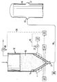
- FIG. 1 the figure represents schematically a sectional view of an apparatus of the invention.
- the drawing is of the process flow type in which auxiliary equipment, such as pumps, compressors, cleaning devices, etc. are not shown.
- an apparatus for controlling the suspension density of a particulate solids and gas mixture pneumatically conveyed via conduit 18 from a vessel, such as a feed hopper 10, to means for injecting the mixture into a reactor 16, such as a burner 17, includes a hopper 10 advantageously including injection of gas into the lower portion thereof.
- Gas such as nitrogen, carbon dioxide, or synthesis gas
- a source 12 can be injected from a source 12 into the lower portion of the hopper through porous material 14, which serves to distribute the gas throughout the bed 15 formed in the lower portion of the hopper 10.
- Injecting gas into the lower portion of the hopper 10 provides for a uniform discharge flow rate of the mixture exiting the hopper 10 and allows for a smaller diameter conduit 18, say 40mm, so as to maintain the high velocities, say 10 m/s, within the conduit 18 which are required to achieve a uniform mass flow rate of the mixture to the burners 17 of the gasifier 16 for the suspension densities used in the present invention.
- At least one radiation source 20 is positioned downstream of injecting the gas from source 12 into the lower portion of the hopper 10 and upstream of the burners 17 to direct radiation to penetrate the cross-sectional area of the mixture.
- a collimator may be used to reduce the scatter of radiation received by the detector 22 to increase the sensitivity of the densitometer at low suspension densities.
- the source 20 is located in proximity to the discharge port 21 but downstream of injecting the gas from source 12 since injecting the gas into the lower portion of the hopper 10 causes the suspension density of the mixture to fluctuate.
- another source (not shown) can be located downstream of the discharge port 21 but upstream of the burner 17.
- another source (not shown) can be located downstream of the discharge port 21 but upstream of the burner 17.
- the source and detector are located in close proximity to injecting transport gas from source 30, then correction of the suspension density would be required for the reason stated above.
- At least one radiation detector/transmitter 22 is positioned substantially diametrically opposite the source 20 to receive radiation transmitted from the source 20 after it has penetrated at least a portion of the mixture.
- the detector/transmitter 22 includes means for converting the received radiation to yield a determination of the suspension density of the mixture. It is to be recognized that this detection/transmittal could be performed in any other manner well known to the art.
- Signals relative to the determined suspension density of the mixture are transmitted from the detector/transmitter 22 a processor-controller 25.
- the processor-controller 25 compares the determined suspension density with a preselected value. If the determined suspension density is higher than the preselected value, then the suspension density of the mixture can be decreased to provide a uniform, constant mass flow rate to the gasifier by increasing the rate of injecting gas from source 12 by actuating flow control valve 27. In a like manner, if the determined suspension density is lower than a preselected value, then the suspension density of the mixture can be increased to provide a uniform, constant mass flow rate to the gasifier by decreasing the rate of injecting gas from source 12.
- the figure illustrates that the processor-controller 25 transmits signals, shown for ease of illustration as dashed line 26, to actuate valve 27 for increasing or decreasing the flow rate of the gas injected from source 12.
- gas can be vented from the hopper 10 by actuating flow control valve 28 via transmission of a signal 29 from the processor-controller 25.
Landscapes
- Chemical & Material Sciences (AREA)
- Engineering & Computer Science (AREA)
- Organic Chemistry (AREA)
- Combustion & Propulsion (AREA)
- General Physics & Mathematics (AREA)
- Physics & Mathematics (AREA)
- Oil, Petroleum & Natural Gas (AREA)
- Automation & Control Theory (AREA)
- Power Engineering (AREA)
- Chemical Kinetics & Catalysis (AREA)
- Fluid Mechanics (AREA)
- Feeding And Controlling Fuel (AREA)
- Devices And Processes Conducted In The Presence Of Fluids And Solid Particles (AREA)
- Regulation And Control Of Combustion (AREA)
Applications Claiming Priority (2)
| Application Number | Priority Date | Filing Date | Title |
|---|---|---|---|
| US07/098,179 US5127772A (en) | 1987-09-18 | 1987-09-18 | Method and apparatus for the control of suspension density by use of a radiation source |
| US98179 | 1993-07-28 |
Publications (3)
| Publication Number | Publication Date |
|---|---|
| EP0308027A2 true EP0308027A2 (de) | 1989-03-22 |
| EP0308027A3 EP0308027A3 (en) | 1989-10-11 |
| EP0308027B1 EP0308027B1 (de) | 1993-09-01 |
Family
ID=22267781
Family Applications (1)
| Application Number | Title | Priority Date | Filing Date |
|---|---|---|---|
| EP88202000A Expired - Lifetime EP0308027B1 (de) | 1987-09-18 | 1988-09-13 | Dichteregelung einer Suspension unter Verwendung einer Strahlungsquelle |
Country Status (8)
| Country | Link |
|---|---|
| US (1) | US5127772A (de) |
| EP (1) | EP0308027B1 (de) |
| JP (1) | JP2719794B2 (de) |
| CN (1) | CN1013926B (de) |
| AU (1) | AU602610B2 (de) |
| CA (1) | CA1318720C (de) |
| DE (1) | DE3883671T2 (de) |
| ZA (1) | ZA886919B (de) |
Cited By (7)
| Publication number | Priority date | Publication date | Assignee | Title |
|---|---|---|---|---|
| FR2655053A1 (fr) * | 1989-11-24 | 1991-05-31 | Inst Francais Du Petrole | Procede et dispositif de regulation des conditions de fonctionnement d'un reacteur de craquage catalytique utilisant une source de rayonnements ionisants. |
| FR2670204A1 (fr) * | 1990-12-10 | 1992-06-12 | Inst Francais Du Petrole | Procede et dispositif de regulation des conditions de fonctionnement d'un reacteur de conversion catalytique d'un compose heteroatomique utilisant une source de rayonnements ionisants. |
| EP0510341A1 (de) * | 1991-04-25 | 1992-10-28 | Krupp Koppers GmbH | Verfahren zur Steuerung des Betriebsablaufes eines Vergasungsreaktors |
| EP0522905A1 (de) * | 1991-07-10 | 1993-01-13 | Total Raffinage Distribution S.A. | Verfahren und Apparat zur kontinuierlichen Erneuerung der Katalysatormasse in einem Fliessbett |
| WO1999048602A1 (en) * | 1998-03-26 | 1999-09-30 | Renner Herrmann S.A. | Apparatus and process for the continuous preparation of a fluid with automatic adjustment of the properties thereof |
| WO2001097962A1 (en) * | 2000-06-22 | 2001-12-27 | Chr. Hansen A/S | On-line monitoring and/or control of headspace in a fluid bed reactor system |
| DE102008027336A1 (de) * | 2008-06-07 | 2009-12-17 | Forschungszentrum Karlsruhe Gmbh | Vorrichtung und Verfahren zur Bestimmung einer Partikelumwandlungsintensität |
Families Citing this family (9)
| Publication number | Priority date | Publication date | Assignee | Title |
|---|---|---|---|---|
| DE19900655C1 (de) * | 1999-01-11 | 2000-10-12 | Kurt Wolf Velco Ges Fuer Foerd | Vorrichtung zur Erzeugung stetiger und beliebig starker Schüttgutströme |
| US7128812B1 (en) * | 2001-03-19 | 2006-10-31 | Cupit Carl E | Apparatus and method for determining the level in a coke drum |
| US20090218371A1 (en) * | 2003-03-25 | 2009-09-03 | Wouter Detlof Berggren | Sluice Vessel and Method of Operating Such a Sluice Vessel |
| DE102008014475A1 (de) * | 2008-03-17 | 2009-11-12 | Uhde Gmbh | Verfahren und Vorrichtung zur dosierten Entnahme eines fein- bis grobkörnigen Feststoffes oder Feststoffgemisches aus einem Vorratsbehälter |
| US8377387B2 (en) | 2010-06-23 | 2013-02-19 | General Electric Company | Fluidization device for solid fuel particles |
| JP6121309B2 (ja) * | 2013-11-08 | 2017-04-26 | 三菱日立パワーシステムズ株式会社 | チャー供給ホッパ、チャー回収装置及びガス化炉システム |
| JP6695163B2 (ja) * | 2016-02-17 | 2020-05-20 | 三菱日立パワーシステムズ株式会社 | 微粉燃料供給装置及び方法、ガス化複合発電設備 |
| CN108748861B (zh) * | 2018-08-02 | 2024-12-13 | 广州金吉拉链制造有限公司 | 一种拉链制作设备 |
| CN113717757B (zh) * | 2021-11-03 | 2022-02-08 | 华能(天津)煤气化发电有限公司 | 一种粉煤加压输送的变比例反馈调节方法 |
Family Cites Families (15)
| Publication number | Priority date | Publication date | Assignee | Title |
|---|---|---|---|---|
| US2924489A (en) * | 1954-11-09 | 1960-02-09 | Beckmann Heinrich | Process and apparatus for conveying finely divided material |
| FR1230526A (fr) * | 1959-03-21 | 1960-09-16 | Siderurgie Fse Inst Rech | Dispositif de régulation automatique d'un distributeur de poudre sous pression |
| US3514217A (en) * | 1968-02-23 | 1970-05-26 | Shell Oil Co | Method of controlling pipeline slurries |
| DE2554565A1 (de) * | 1975-12-04 | 1977-06-16 | Otto & Co Gmbh Dr C | Anlage zur druckvergasung feinkoerniger brennstoffe |
| US4089563A (en) * | 1977-05-11 | 1978-05-16 | Societe Anonyme Des Etablissements Neu | Apparatus for pneumatic conveyance of pulverulent or granular materials |
| DE2757032A1 (de) * | 1977-12-21 | 1979-06-28 | Krupp Koppers Gmbh | Verfahren zur ermittlung des bei der partialoxydation von feinkoernigen bis staubfoermigen festen brennstoffen dem vergaser zugefuehrten brennstoffstromes |
| US4186306A (en) * | 1977-12-02 | 1980-01-29 | Johns-Manville Corporation | Perlite expansion density control system |
| US4611955A (en) * | 1980-07-23 | 1986-09-16 | Conoco Inc. | Slurry pump tram control apparatus |
| EP0074365A1 (de) * | 1981-03-16 | 1983-03-23 | Mount Isa Mines Limited | Messen der massendichte von teilförmigem material |
| DD206309A3 (de) * | 1981-07-17 | 1984-01-18 | Kretschmer Horst | Verfahren zur regelung von massenstroemen |
| US4490077A (en) * | 1981-07-28 | 1984-12-25 | Nippon Kokan Kabushiki Kaisha | Apparatus for continuously measuring flow rate of fine material flowing through transport pipe |
| US4415296A (en) * | 1981-09-14 | 1983-11-15 | Kamyr, Inc. | Materials transfer system and methodology |
| US4498819A (en) * | 1982-11-08 | 1985-02-12 | Conoco Inc. | Multipoint slurry injection junction |
| US4779762A (en) * | 1984-05-30 | 1988-10-25 | Nordson Corporation | Method and apparatus for controlling the gas content of dispensed hot melt thermoplastic adhesive foam |
| US4613259A (en) * | 1984-11-28 | 1986-09-23 | United Technologies Corporation | Apparatus for controlling powder flow rate in a carrier gas |
-
1987
- 1987-09-18 US US07/098,179 patent/US5127772A/en not_active Expired - Lifetime
-
1988
- 1988-09-13 DE DE88202000T patent/DE3883671T2/de not_active Expired - Lifetime
- 1988-09-13 EP EP88202000A patent/EP0308027B1/de not_active Expired - Lifetime
- 1988-09-16 JP JP63230241A patent/JP2719794B2/ja not_active Expired - Lifetime
- 1988-09-16 ZA ZA886919A patent/ZA886919B/xx unknown
- 1988-09-16 CA CA000577644A patent/CA1318720C/en not_active Expired - Lifetime
- 1988-09-16 CN CN88106712A patent/CN1013926B/zh not_active Expired
- 1988-09-16 AU AU22350/88A patent/AU602610B2/en not_active Expired
Cited By (13)
| Publication number | Priority date | Publication date | Assignee | Title |
|---|---|---|---|---|
| FR2655053A1 (fr) * | 1989-11-24 | 1991-05-31 | Inst Francais Du Petrole | Procede et dispositif de regulation des conditions de fonctionnement d'un reacteur de craquage catalytique utilisant une source de rayonnements ionisants. |
| FR2670204A1 (fr) * | 1990-12-10 | 1992-06-12 | Inst Francais Du Petrole | Procede et dispositif de regulation des conditions de fonctionnement d'un reacteur de conversion catalytique d'un compose heteroatomique utilisant une source de rayonnements ionisants. |
| EP0490742A1 (de) * | 1990-12-10 | 1992-06-17 | Institut Français du Pétrole | Verfahren zur Regulierung von Funktionierungsumständen von einem Reaktor zur katalytischen Umsetzung von einer Sauerstoffverbindung unter Verwendung einer Quelle von ionisierenden Strahlungen |
| EP0510341A1 (de) * | 1991-04-25 | 1992-10-28 | Krupp Koppers GmbH | Verfahren zur Steuerung des Betriebsablaufes eines Vergasungsreaktors |
| US5512166A (en) * | 1991-07-10 | 1996-04-30 | Total Raffinage Distribution, S.A. | Process and apparatus for the continuous replacement of the catalyst in a moving-bed unit |
| FR2678944A1 (fr) * | 1991-07-10 | 1993-01-15 | Total Raffinage Distribution | Procede et dispositif pour le remplacement en continu du catalyseur dans une unite a lit mobile. |
| EP0522905A1 (de) * | 1991-07-10 | 1993-01-13 | Total Raffinage Distribution S.A. | Verfahren und Apparat zur kontinuierlichen Erneuerung der Katalysatormasse in einem Fliessbett |
| WO1999048602A1 (en) * | 1998-03-26 | 1999-09-30 | Renner Herrmann S.A. | Apparatus and process for the continuous preparation of a fluid with automatic adjustment of the properties thereof |
| US6533449B1 (en) | 1998-03-26 | 2003-03-18 | Renner Herrmann S.A. | Apparatus and process for the continuous preparation of a fluid, utilizing a fluid recycling means including a buffer |
| WO2001097962A1 (en) * | 2000-06-22 | 2001-12-27 | Chr. Hansen A/S | On-line monitoring and/or control of headspace in a fluid bed reactor system |
| US7309610B2 (en) | 2000-06-22 | 2007-12-18 | Chr. Hansen A/S | On-line monitoring and/or control of headspace in a fluid bed reactor system |
| DE102008027336A1 (de) * | 2008-06-07 | 2009-12-17 | Forschungszentrum Karlsruhe Gmbh | Vorrichtung und Verfahren zur Bestimmung einer Partikelumwandlungsintensität |
| DE102008027336B4 (de) * | 2008-06-07 | 2010-07-08 | Karlsruher Institut für Technologie | Vorrichtung und Verfahren zur Bestimmung einer Partikelumwandlungsintensität |
Also Published As
| Publication number | Publication date |
|---|---|
| EP0308027B1 (de) | 1993-09-01 |
| JP2719794B2 (ja) | 1998-02-25 |
| CN1013926B (zh) | 1991-09-18 |
| AU2235088A (en) | 1989-03-23 |
| DE3883671T2 (de) | 1993-12-23 |
| CA1318720C (en) | 1993-06-01 |
| ZA886919B (en) | 1989-05-30 |
| EP0308027A3 (en) | 1989-10-11 |
| CN1032496A (zh) | 1989-04-26 |
| JPH01114619A (ja) | 1989-05-08 |
| AU602610B2 (en) | 1990-10-18 |
| DE3883671D1 (de) | 1993-10-07 |
| US5127772A (en) | 1992-07-07 |
Similar Documents
| Publication | Publication Date | Title |
|---|---|---|
| CA1318720C (en) | Control of suspension density using radiation source | |
| US4941779A (en) | Compartmented gas injection device | |
| EP0348007B1 (de) | Austragvorrichtung mit Belüftung | |
| US7607398B2 (en) | Method and device for the regulated feed of pulverized fuel to an entrained flow gasifier | |
| US4531949A (en) | Entrained flow coal gasification process | |
| US5129766A (en) | Aeration tube discharge control device | |
| US4480559A (en) | Coal and char burner | |
| US4146370A (en) | Process and apparatus for the partial combustion of coal powder | |
| US4721514A (en) | Coal gasification method using coal powder | |
| US4830545A (en) | Feed line design | |
| US4749383A (en) | Method for producing low and medium BTU gas from coal | |
| EP0348008B1 (de) | Entladungssteuerungsvorrichtung mit Belüftungsrohr | |
| EP0308024B1 (de) | Facheinrichtung für Gas-Injektion | |
| US4834588A (en) | Feed line-pulsed gas injection | |
| US4750434A (en) | Mill/dryer gas temperature control | |
| Gutierrez et al. | Fluidized-bed gasification of some Western Canadian coals | |
| US4844663A (en) | Feed line-ultrasonic activated gas injection | |
| JPH083361B2 (ja) | 微粉原料ガス化用バーナ及び微粉原料ガス化装置 | |
| CN102428060A (zh) | 生产合成气的方法以及装置 | |
| CA1320152C (en) | Stripping and depressurization of solids and gas mixture | |
| EP1207191A2 (de) | Festbettvergaser und Verfahren zur Vergasung von organischen Abfällen | |
| WO2006003454A1 (en) | Process for treating a carbonaceous material | |
| KR19980070746A (ko) | 열에 의한 폐기물 처리장치중 온도조절 방법 및 폐기물 처리장치 | |
| JPH086102B2 (ja) | 噴流層ガス化装置 |
Legal Events
| Date | Code | Title | Description |
|---|---|---|---|
| PUAI | Public reference made under article 153(3) epc to a published international application that has entered the european phase |
Free format text: ORIGINAL CODE: 0009012 |
|
| AK | Designated contracting states |
Kind code of ref document: A2 Designated state(s): DE GB IT NL |
|
| PUAL | Search report despatched |
Free format text: ORIGINAL CODE: 0009013 |
|
| AK | Designated contracting states |
Kind code of ref document: A3 Designated state(s): DE GB IT NL |
|
| 17P | Request for examination filed |
Effective date: 19900220 |
|
| 17Q | First examination report despatched |
Effective date: 19901120 |
|
| GRAA | (expected) grant |
Free format text: ORIGINAL CODE: 0009210 |
|
| AK | Designated contracting states |
Kind code of ref document: B1 Designated state(s): DE GB IT NL |
|
| REF | Corresponds to: |
Ref document number: 3883671 Country of ref document: DE Date of ref document: 19931007 |
|
| ITF | It: translation for a ep patent filed | ||
| PLBE | No opposition filed within time limit |
Free format text: ORIGINAL CODE: 0009261 |
|
| STAA | Information on the status of an ep patent application or granted ep patent |
Free format text: STATUS: NO OPPOSITION FILED WITHIN TIME LIMIT |
|
| 26N | No opposition filed | ||
| REG | Reference to a national code |
Ref country code: GB Ref legal event code: IF02 |
|
| PGFP | Annual fee paid to national office [announced via postgrant information from national office to epo] |
Ref country code: DE Payment date: 20070926 Year of fee payment: 20 |
|
| PGFP | Annual fee paid to national office [announced via postgrant information from national office to epo] |
Ref country code: GB Payment date: 20070817 Year of fee payment: 20 |
|
| PGFP | Annual fee paid to national office [announced via postgrant information from national office to epo] |
Ref country code: NL Payment date: 20070925 Year of fee payment: 20 Ref country code: IT Payment date: 20070924 Year of fee payment: 20 |
|
| REG | Reference to a national code |
Ref country code: GB Ref legal event code: PE20 Expiry date: 20080912 |
|
| NLV7 | Nl: ceased due to reaching the maximum lifetime of a patent |
Effective date: 20080913 |
|
| PG25 | Lapsed in a contracting state [announced via postgrant information from national office to epo] |
Ref country code: NL Free format text: LAPSE BECAUSE OF EXPIRATION OF PROTECTION Effective date: 20080913 |
|
| PG25 | Lapsed in a contracting state [announced via postgrant information from national office to epo] |
Ref country code: GB Free format text: LAPSE BECAUSE OF EXPIRATION OF PROTECTION Effective date: 20080912 |