EP0307971B1 - Mandrel for the connection of two pipe ends - Google Patents
Mandrel for the connection of two pipe ends Download PDFInfo
- Publication number
- EP0307971B1 EP0307971B1 EP88117883A EP88117883A EP0307971B1 EP 0307971 B1 EP0307971 B1 EP 0307971B1 EP 88117883 A EP88117883 A EP 88117883A EP 88117883 A EP88117883 A EP 88117883A EP 0307971 B1 EP0307971 B1 EP 0307971B1
- Authority
- EP
- European Patent Office
- Prior art keywords
- securing
- sleeve
- fingers
- bushing
- coupling
- Prior art date
- Legal status (The legal status is an assumption and is not a legal conclusion. Google has not performed a legal analysis and makes no representation as to the accuracy of the status listed.)
- Expired - Lifetime
Links
Images
Classifications
-
- F—MECHANICAL ENGINEERING; LIGHTING; HEATING; WEAPONS; BLASTING
- F16—ENGINEERING ELEMENTS AND UNITS; GENERAL MEASURES FOR PRODUCING AND MAINTAINING EFFECTIVE FUNCTIONING OF MACHINES OR INSTALLATIONS; THERMAL INSULATION IN GENERAL
- F16L—PIPES; JOINTS OR FITTINGS FOR PIPES; SUPPORTS FOR PIPES, CABLES OR PROTECTIVE TUBING; MEANS FOR THERMAL INSULATION IN GENERAL
- F16L37/00—Couplings of the quick-acting type
- F16L37/08—Couplings of the quick-acting type in which the connection between abutting or axially overlapping ends is maintained by locking members
- F16L37/12—Couplings of the quick-acting type in which the connection between abutting or axially overlapping ends is maintained by locking members using hooks, pawls or other movable or insertable locking members
- F16L37/138—Couplings of the quick-acting type in which the connection between abutting or axially overlapping ends is maintained by locking members using hooks, pawls or other movable or insertable locking members using an axially movable sleeve
-
- F—MECHANICAL ENGINEERING; LIGHTING; HEATING; WEAPONS; BLASTING
- F02—COMBUSTION ENGINES; HOT-GAS OR COMBUSTION-PRODUCT ENGINE PLANTS
- F02M—SUPPLYING COMBUSTION ENGINES IN GENERAL WITH COMBUSTIBLE MIXTURES OR CONSTITUENTS THEREOF
- F02M55/00—Fuel-injection apparatus characterised by their fuel conduits or their venting means; Arrangements of conduits between fuel tank and pump F02M37/00
- F02M55/004—Joints; Sealings
-
- F—MECHANICAL ENGINEERING; LIGHTING; HEATING; WEAPONS; BLASTING
- F16—ENGINEERING ELEMENTS AND UNITS; GENERAL MEASURES FOR PRODUCING AND MAINTAINING EFFECTIVE FUNCTIONING OF MACHINES OR INSTALLATIONS; THERMAL INSULATION IN GENERAL
- F16L—PIPES; JOINTS OR FITTINGS FOR PIPES; SUPPORTS FOR PIPES, CABLES OR PROTECTIVE TUBING; MEANS FOR THERMAL INSULATION IN GENERAL
- F16L33/00—Arrangements for connecting hoses to rigid members; Rigid hose connectors, i.e. single members engaging both hoses
- F16L33/30—Arrangements for connecting hoses to rigid members; Rigid hose connectors, i.e. single members engaging both hoses comprising parts inside the hoses only
-
- F—MECHANICAL ENGINEERING; LIGHTING; HEATING; WEAPONS; BLASTING
- F16—ENGINEERING ELEMENTS AND UNITS; GENERAL MEASURES FOR PRODUCING AND MAINTAINING EFFECTIVE FUNCTIONING OF MACHINES OR INSTALLATIONS; THERMAL INSULATION IN GENERAL
- F16L—PIPES; JOINTS OR FITTINGS FOR PIPES; SUPPORTS FOR PIPES, CABLES OR PROTECTIVE TUBING; MEANS FOR THERMAL INSULATION IN GENERAL
- F16L37/00—Couplings of the quick-acting type
- F16L37/08—Couplings of the quick-acting type in which the connection between abutting or axially overlapping ends is maintained by locking members
- F16L37/12—Couplings of the quick-acting type in which the connection between abutting or axially overlapping ends is maintained by locking members using hooks, pawls or other movable or insertable locking members
- F16L37/133—Couplings of the quick-acting type in which the connection between abutting or axially overlapping ends is maintained by locking members using hooks, pawls or other movable or insertable locking members using flexible hooks
-
- F—MECHANICAL ENGINEERING; LIGHTING; HEATING; WEAPONS; BLASTING
- F02—COMBUSTION ENGINES; HOT-GAS OR COMBUSTION-PRODUCT ENGINE PLANTS
- F02M—SUPPLYING COMBUSTION ENGINES IN GENERAL WITH COMBUSTIBLE MIXTURES OR CONSTITUENTS THEREOF
- F02M2200/00—Details of fuel-injection apparatus, not otherwise provided for
- F02M2200/85—Mounting of fuel injection apparatus
- F02M2200/853—Mounting of fuel injection apparatus involving use of quick-acting mechanism, e.g. clips
Definitions
- the invention relates to a coupling sleeve for connecting the ends of two lines for flowing media, in particular for fuel lines on internal combustion engines, with a sleeve part which has at least one insertion opening for receiving a line end.
- a coupling sleeve which has a plug-in part provided with an external O-ring as a sealing element and a coupling part into which the plug-in part is inserted and which is provided with resilient catches which are in a recess on Insert the plug-in part and lock it against being pulled out.
- the resilient catches are connected in one piece via spiral springs to a sliding sleeve, which enables unlocking.
- a hose coupling of this type is suitable for garden hoses, but not as a coupling for fuel lines on motor vehicles, since the necessary freedom from play with regard to the vibrations present during operation is not guaranteed and there is therefore a risk of unintentional loosening and / or breaking of individual parts.
- a similar hose coupling is known from US-A-4 451 069.
- This consists of a plug-in part provided with a securing sleeve and carrying an external seal and a socket part to be connected to the other line end and provided with exposed securing fingers.
- it is not possible to directly insert a line end provided with a bead into the socket part, but rather a plug-in part or a socket part must be connected to both line ends.
- a disadvantage of this design is also that the securing of the plug connection with the retaining sleeve pushed back is insufficient, so that separation is possible even with low axial forces.
- the support of the coupling sleeves against lateral forces is insufficient here, especially in the operating position, because of the slight overlap.
- the invention is based on the object of creating a socket connection of the type described at the outset which fulfills the requirements listed above.
- At least two securing fingers which can be deflected transversely to the insertion opening are arranged on the socket part in the region of the insertion opening, the free ends of which are each provided with radially inwardly directed projections which act on the outer wall of a tubular elastic sealing body forming the insertion opening, so that an axially displaceable and snap-in locking sleeve is provided on the sleeve part, which in its operating position engages around the free ends of the locking fingers essentially without play.
- a coupling sleeve designed in this way has a number of advantages.
- the free end of the pipe to be connected either a pipe or a hose, with a pipe insert in the end area can be inserted into the insertion opening of the socket part in a simple plug-in installation, the tubular sealing body made of elastic material in the socket part having the cable end pushed in on it Seals around the outer surface.
- the free opening of the elastic sealing body has a somewhat smaller diameter from the outer diameter of the line end to be inserted, so that when the line end is inserted, the sealing body is correspondingly pressed and the required Sealing force is present.
- the tubular sealing body in contrast to the previously known couplings, has a sufficient volume of deformation, additional deformations of the elastic sealing body will not impair the sealing force when the coupling sleeve is subjected to transverse forces.
- the inserted line end is encompassed in a sealing manner on its outer surface by the sealing body, a contact force between the sealing body and the line end being effective in the area of the lugs of the securing fingers due to the pushed-over securing sleeve, which improves the sealing effect.
- the annular projection arranged at the end of the line now lies within the sealing body, there is nevertheless a positive-locking securing of the end of the line against being pulled out by the projections of the securing fingers.
- protrusions are provided on the securing fingers in the area of the lugs on the sealing body on the outside, which form a detent defining the operating position in cooperation with the securing sleeve, then, with a corresponding shaping of the protrusions, both securing the operating position and the desired increase can be achieved achieve the sealing effect, which is not reduced by transverse forces acting on the line.
- a preferred embodiment of the invention provides that the securing fingers have a fixed end are attached to a retaining ring which engages around the socket part in a form-fitting manner.
- the arrangement of the locking fingers as a separate component requires an additional operation when assembling the clutch sleeve, since the retaining ring and the sleeve part initially must be put together and then the locking sleeve must be pushed over.
- the particular advantage of this design is that it makes it possible to directly vulcanize the elastic sealing body into a cup-like extension in the sleeve part that is open against the direction of insertion, since the edge of the insertion opening is exposed, so that the sleeve part and the tool are moved in rotation relative to one another can and the elastic material can be introduced.
- the particular advantage here lies in the fact that by vulcanizing the elastic sealing body, the connection between the sealing body and the socket part is absolutely tight, so that only the appropriate compression between the sealing body and the inserted pipe part means that the seal between the socket part and the line end is to be taken care of.
- the retaining ring carrying the securing fingers is divided.
- the retaining ring can either consist of two loose sections or can be provided in one piece with a thin flexible connection, as is possible in the production of a plastic in the form of a so-called "film hinge".
- the retaining ring is expediently bowl-shaped and encompasses a correspondingly shaped retaining web on the socket part, so that the retaining ring is positively and axially displaceably connected to the socket part with the securing fingers.
- the securing fingers are colored differently than the securing sleeve, at least in the area of their free ends. This has the advantage that in the assembly position described above, the assembly position is visible through the color of the securing fingers, so that an optical check is also possible as to whether the securing sleeve is also shifted into the operating position after assembly. With the appropriate length of the securing sleeve this completely covers the securing fingers in the operating position.
- At least the securing sleeve is made of metal and is guided on the sleeve part at a radial distance and, in the operating position, covers the sleeve part including the securing fingers and part of the flexible hose line connected to the sleeve part. This allows the fire resistance to be increased even in the case of plug-in socket parts made of plastic, as is desirable, for example, for fuel lines.
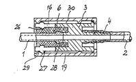
- the embodiment shown has an elastic sealing body 6 which is fixedly connected to a socket part 3, which is tubular and which seals the inserted end of the pipeline 1 on the outside over a greater length in a sealing manner.
- the socket part 3 with its peg-like extension 4 for connecting a hose line 2 forms, together with securing fingers 16, a cylindrical receiving space for the tubular sealing body 6, the securing fingers 16 lying loosely on the outside of the sealing body 6 in the installed position.
- the sleeve part 3 is surrounded by an axially displaceable securing sleeve 19.
- the securing fingers 16 are provided in the region of their free ends with projections 26 on the inside as well as with projections 27 on the outside.
- the pipeline 1 provided with a bead 28 at its end can be pressed into the sealing body 6, since the securing fingers 16 bend outwards correspondingly due to their elasticity.
- the securing sleeve 19 is advanced into the operating position shown, and so far until one on the inside annular projection 29 which also engages around a ring forming projections 27 of the locking fingers 16.
- the securing sleeve 19 is made of metal, in the case of parts which are otherwise made of plastic, then there is an additional increase in the fire resistance of the coupling sleeve, since a heat-conducting connection between these parts is limited to a few narrow zones and the intermediate space 30 has an insulating effect.
- An increase in fire resistance to, for example, three minutes can be life-saving in the event of an accident when used in motor vehicle construction.
- the securing fingers 16 are integrally formed on the sleeve part 3.
Abstract
Description
Die Erfindung betrifft eine Kupplungsmuffe zum Verbinden der Enden zweier Leitungen für strömende Medien, insbesondere für Kraftstoffleitungen an Verbrennungsmotoren, mit einem Muffenteil, das wenigstens eine Einschuböffnung zur Aufnahme eines Leitungsendes aufweist.The invention relates to a coupling sleeve for connecting the ends of two lines for flowing media, in particular for fuel lines on internal combustion engines, with a sleeve part which has at least one insertion opening for receiving a line end.
In einer Vielzahl von Einsatzfällen müssen bei Maschinen Nebenaggregate über Rohr- und/oder Schlauchleitungen miteinander verbunden werden. Hierbei ist vielfach auch die Notwendigkeit gegeben, daß eine starre Rohrleitung, beispielsweise aus Metall, mit einer biegsamen Schlauchleitung aus Gummi oder Kunststoff verbunden werden muß, wie dies beispielsweise für Kraftstoffleitungen an Verbrennungsmotoren üblich ist. Gerade im Fall der Verbrennungsmotoren, insbesondere bei der Automobil-Serienproduktion, kommt es vor allem darauf an, daß zum einen die Kupplungsmuffe leicht zu montieren ist, insbesondere durch eine einfache Steckmontage, andererseits die Muffenverbindung aber so fest ist, daß sie sich auch bei den starken Erschütterungen beim Betrieb eines Kraftfahrzeuges nicht lösen kann. Gleichwohl muß die Muffenverbindung so ausgebildet sein, daß zu Reparaturzwecken beide Leitungsteile voneinander gelöst werden können, wobei es wichtig ist, daß die Außenfläche der Leitungsenden, die gleichzeitig als Dichtenden dienen, durch die Muffenverbindung nicht beschädigt werden.In a large number of applications, machine ancillaries must be connected to one another via pipe and / or hose lines. In many cases there is also the need for a rigid pipeline, for example made of metal, to be connected to a flexible hose made of rubber or plastic, as is customary, for example, for fuel lines on internal combustion engines. Especially in the case of internal combustion engines, particularly in the case of series production of automobiles, it is particularly important that, on the one hand, the coupling sleeve is easy to assemble, in particular by simple plug-in assembly, and, on the other hand, the sleeve connection but it is so firm that it cannot be released even with the strong vibrations when operating a motor vehicle. Nevertheless, the socket connection must be designed such that both line parts can be detached from one another for repair purposes, it being important that the outer surface of the line ends, which also serve as sealing ends, not be damaged by the socket connection.
Aus der DE-A-2 734 117 ist eine Kupplungsmuffe bekannt, die einen mit einem außenliegenden O-Ring als Dichtelement versehenen Steckteil und einen Kupplungsteil aufweist, in den der Steckteil eingeschoben wird und der mit federnden Rasten versehen ist, die in eine Ausnehmung am Steckteil eingreifen und dieses gegen Herausziehen arretieren. Die federnden Rasten sind über Biegefedern einstückig mit einer Schiebehülse verbunden, die eine Entriegelung ermöglicht. Eine Schlauchkupplung dieser Bauart ist für Gartenschläuche geeignet, jedoch nicht als Kupplung für Kraftstoffleitungen an Kraftfahrzeugen, da die notwendige Spielfreiheit im Hinblick auf die im Betrieb vorhandenen Erschütterungen nicht gewährleistet ist und somit die Gefahr eines unbeabsichtigten Lösens und/oder ein Brechen von Einzelteilen besteht.From DE-A-2 734 117 a coupling sleeve is known which has a plug-in part provided with an external O-ring as a sealing element and a coupling part into which the plug-in part is inserted and which is provided with resilient catches which are in a recess on Insert the plug-in part and lock it against being pulled out. The resilient catches are connected in one piece via spiral springs to a sliding sleeve, which enables unlocking. A hose coupling of this type is suitable for garden hoses, but not as a coupling for fuel lines on motor vehicles, since the necessary freedom from play with regard to the vibrations present during operation is not guaranteed and there is therefore a risk of unintentional loosening and / or breaking of individual parts.
Aus der US-A-4 451 069 ist eine ähnliche Schlauchkupplung bekannt. Diese besteht aus einem mit einer Sicherungshülse versehenen und eine außenliegende Dichtung getragenden Steckteil und einem mit dem anderen Leitungsende zu verbindenden, mit freiliegenden Sicherungsfingern versehenen Muffenteil. Auch hier ist es nicht möglich, in den Muffenteil unmittelbar ein mit einer Wulst versehenes Leitungsende einzuschieben, sondern es muß vielmehr jeweils mit beiden Leitungsenden ein Steckteil bzw. ein Muffenteil verbunden werden. Ein Nachteil dieser Bauform besteht ferner darin, daß die Sicherung der Steckverbindung mit zurückgeschobener Sicherungshülse ungenügend ist, so daß eine Trennung schon bei geringen Axialkräften möglich ist. Die Abstützung der Kupplungsmuffen gegenüber Querkräften ist hierbei wegen der geringen Überdeckung gerade in der Betriebsstellung ungenügend.A similar hose coupling is known from US-A-4 451 069. This consists of a plug-in part provided with a securing sleeve and carrying an external seal and a socket part to be connected to the other line end and provided with exposed securing fingers. Here, too, it is not possible to directly insert a line end provided with a bead into the socket part, but rather a plug-in part or a socket part must be connected to both line ends. A disadvantage of this design is also that the securing of the plug connection with the retaining sleeve pushed back is insufficient, so that separation is possible even with low axial forces. The support of the coupling sleeves against lateral forces is insufficient here, especially in the operating position, because of the slight overlap.
Der Erfindung liegt nun die Aufgabe zugrunde, eine Muffenverbindung der eingangs bezeichneten Art zu schaffen, die die vorstehend aufgeführten Forderungen erfüllt.The invention is based on the object of creating a socket connection of the type described at the outset which fulfills the requirements listed above.
Dies wird erfindungsgemäß dadurch gelöst, daß am Muffenteil im Bereich der Einschuböffnung wenigstens zwei quer zur Einschuböffnung auslenkbare Sicherungsfinger angeordnet sind, deren freie Enden jeweils mit radial nach innen gerichteten Ansätzen versehen sind, die auf die Außenwandung eines die Einschuböffnung bildenden rohrförmigen elastischen Dichtungskörpers einwirken, so daß eine auf dem Muffenteil axial verschiebbare und auf diesem einrastbare Sicherungshülse vorgesehen ist, die in ihrer Betriebsstellung die freien Enden der Sicherungsfinger im wesentlichen Spielfrei umgreift.This is achieved according to the invention in that at least two securing fingers which can be deflected transversely to the insertion opening are arranged on the socket part in the region of the insertion opening, the free ends of which are each provided with radially inwardly directed projections which act on the outer wall of a tubular elastic sealing body forming the insertion opening, so that an axially displaceable and snap-in locking sleeve is provided on the sleeve part, which in its operating position engages around the free ends of the locking fingers essentially without play.
Eine derart ausgebildete Kupplungsmuffe weist eine Reihe von Vorteilen auf. Zur Montage kann das freie Ende der anzuschließenden Leitung, entweder ein Rohr oder aber auch ein Schlauch, mit einem Rohreinsatz im Endbereich in einfacher Steckmontage in die Einschuböffnung des Muffenteils eingeschoben werden, wobei der im Muffenteil vorhandene rohrförmige Dichtungskörper aus elastischem Material das engeschobene Leitungsende auf seiner Außenfläche dichtend umgreift. Überlicherweise weist hier die freie Öffnung des elastischen Dichtungskörpers einen etwas geringeren Durchmesser auf aus der Außendurchmesser des einzuschiebenden Leitungsendes, so daß bei eingeschobenem Leitungsende der Dichtkörper entsprechend verpreßt wird und die erforderliche Dichtkraft vorhanden ist. Da der rohrförmige Dichtungskörper im Gegensatz zu den bisher bekannten Kupplungen ein ausreichendes Verformungsvolumen aufweist, werden bei einer Belastung der Kupplungsmuffe durch Querkräfte zusätzliche Verformungen des elastischen Dichtungskörpers nicht zu einer Beeinträchtigung der Dichtkraft führen. Das eingeschobene Leitungsende ist über eine erhebliche Länge auf seiner Außenfläche vom Dichtungskörper dichtend umfaßt, wobei im Bereich der Ansätze der Sicherungsfinger durch die übergeschobene Sicherungshülse eine Anpreßkraft zwischen Dichtkörper und Leitungsende wirksam wird, die die Dichtwirkung verbessert. Obwohl der am Leitungsende angeordnete ringförmige Vorsprung nunmehr innerhalb des Dichtungskörpers liegt, ergibt sich gleichwohl eine formschlüssig wirkende Sicherung des Leitungsendes gegen ein Herausziehen durch die Ansätze der Sicherungsfinger.A coupling sleeve designed in this way has a number of advantages. For assembly, the free end of the pipe to be connected, either a pipe or a hose, with a pipe insert in the end area can be inserted into the insertion opening of the socket part in a simple plug-in installation, the tubular sealing body made of elastic material in the socket part having the cable end pushed in on it Seals around the outer surface. Usually, the free opening of the elastic sealing body has a somewhat smaller diameter from the outer diameter of the line end to be inserted, so that when the line end is inserted, the sealing body is correspondingly pressed and the required Sealing force is present. Since the tubular sealing body, in contrast to the previously known couplings, has a sufficient volume of deformation, additional deformations of the elastic sealing body will not impair the sealing force when the coupling sleeve is subjected to transverse forces. The inserted line end is encompassed in a sealing manner on its outer surface by the sealing body, a contact force between the sealing body and the line end being effective in the area of the lugs of the securing fingers due to the pushed-over securing sleeve, which improves the sealing effect. Although the annular projection arranged at the end of the line now lies within the sealing body, there is nevertheless a positive-locking securing of the end of the line against being pulled out by the projections of the securing fingers.
Sieht man erfindungsgemäß an den Sicherungsfingern im Bereich der am Dichtungskörper anliegenden Ansätze auf der Außenseite Vorsprünge vor, die im Zusammenwirken mit der Sicherungshülse eine die Betriebsstellung definierende Rast bilden, so läßt sich bei entsprechender Formgebung der Vorsprünge sowohl eine Sicherung der Betriebsstellung als auch die gewünschte Erhöhung der Dichtwirkung erreichen, die sich auch durch auf die Leitung wirkende Querkräfte nicht mindert.If, according to the invention, protrusions are provided on the securing fingers in the area of the lugs on the sealing body on the outside, which form a detent defining the operating position in cooperation with the securing sleeve, then, with a corresponding shaping of the protrusions, both securing the operating position and the desired increase can be achieved achieve the sealing effect, which is not reduced by transverse forces acting on the line.
Während es grundsätzlich möglich ist, das Muffenteil mit den Sicherungsfingern einstückig herzustellen, was insbesondere dann angezeigt ist, wenn elastische Dichtungskörper als gesondertes Bauteil unter Vorspannung in die Einschuböffnung eingesetzt werden, ist in einer bevorzugten Ausgestaltung der Erfindung vorgesehen, daß die Sicherungsfinger mit ihrem festen Ende an einem das Muffenteil formschlüssig umgreifenden Haltering befestigt sind. Die Anordnung der Sicherungsfinger als gesondertes Bauteil erfordert zwar bei der Konfektionierung der Mupplungsmuffe einen zusätzlichen Arbeitsgang, da der Haltering und das Muffenteil zunächst zusammengesteckt werden müssen und anschließend die Sicherungshülse übergeschoben werden muß. Der besondere Vorteil dieser Bauform liegt jedoch darin, daß es hierdurch möglich wird, den elastischen Dichtungskörper in eine gegen die Einschubrichtung geöffnete napfartige Erweiterung im Muffenteil unmittelbar einzuvulkanisieren, da der Rand der Einschuböffnung freiliegt, so daß das Muffenteil und das Werkzeug relativ zueinander drehend bewegt werden können und das elastische Material eingebracht werden kann. Der besondere Vorteil liegt hier vor allem darin, daß durch das Einvulkanisieren des elastischen Dichtungskörpers die Verbindung zwischen Dichtungskörper und Muffenteil absolut dicht ist, so daß nur noch durch entsprechende Verpressung zwischen Dichtungskörper und eingeschobenem Rohrteil für die Abdichtung zwischen Muffenteil und Leitungsende Sorge zu tragen ist.While it is fundamentally possible to manufacture the sleeve part in one piece with the securing fingers, which is particularly indicated when elastic sealing bodies are inserted as a separate component under prestress into the insertion opening, a preferred embodiment of the invention provides that the securing fingers have a fixed end are attached to a retaining ring which engages around the socket part in a form-fitting manner. The arrangement of the locking fingers as a separate component requires an additional operation when assembling the clutch sleeve, since the retaining ring and the sleeve part initially must be put together and then the locking sleeve must be pushed over. The particular advantage of this design, however, is that it makes it possible to directly vulcanize the elastic sealing body into a cup-like extension in the sleeve part that is open against the direction of insertion, since the edge of the insertion opening is exposed, so that the sleeve part and the tool are moved in rotation relative to one another can and the elastic material can be introduced. The particular advantage here lies in the fact that by vulcanizing the elastic sealing body, the connection between the sealing body and the socket part is absolutely tight, so that only the appropriate compression between the sealing body and the inserted pipe part means that the seal between the socket part and the line end is to be taken care of.
In zweckmäßiger Ausgestaltung der Erfindung ist ferner vorgesehen, daß der die Sicherungsfinger tragende Haltering geteilt ist. Der Haltering kann hier entweder aus zwei losen Teilstücken bestehen oder aber einstückig mit einer dünnen biegsamen Verbindung versehen sein, wie dies bei der Herstellung aus einem Kunststoff in Form eines sogenannten "Filmgelenkes" möglich ist. Der Haltering ist zweckmäßigerweise schalenförmig ausgebildet und umgreift einen entsprechend geformten Haltesteg am Muffenteil, so daß der Haltering mit den Sicherungsfingern formschlüssig und axial verschiebbar fest mit dem Muffenteil verbunden ist.In an advantageous embodiment of the invention it is further provided that the retaining ring carrying the securing fingers is divided. The retaining ring can either consist of two loose sections or can be provided in one piece with a thin flexible connection, as is possible in the production of a plastic in the form of a so-called "film hinge". The retaining ring is expediently bowl-shaped and encompasses a correspondingly shaped retaining web on the socket part, so that the retaining ring is positively and axially displaceably connected to the socket part with the securing fingers.
In bevorzugter Ausgestaltung der Erfindung ist ferner vorgesehen, daß die Sicherungsfinger zumindest im Bereich ihrer freien Enden anders gefärbt sind als die Sicherungshülse. Dies hat den Vorteil, daß in der vorstehend beschriebenen Montagestellung die Montagestellung durch die Farbgebung der Sicherungsfinger sichtbar ist, so daß auch eine optische Kontrolle möglich ist, ob nach dem Montieren die Sicherungshülse auch in die Betriebsstellung verschoben ist. Bei entsprechender Längenausbildung der Sicherungshülse überdeckt diese in der Betriebsstellung die Sicherungsfinger vollständig.In a preferred embodiment of the invention it is further provided that the securing fingers are colored differently than the securing sleeve, at least in the area of their free ends. This has the advantage that in the assembly position described above, the assembly position is visible through the color of the securing fingers, so that an optical check is also possible as to whether the securing sleeve is also shifted into the operating position after assembly. With the appropriate length of the securing sleeve this completely covers the securing fingers in the operating position.
In Ausgestaltung der Erfindung ist vorgesehen, daß zumindest die Sicherungshülse aus Metall hergestellt und auf dem Muffenteil mit radialem Abstand geführt ist sowie in Betriebsstellung das Muffenteil einschließlich der Sicherungsfinger sowie einen Teil der mit dem Muffenteil verbundenen flexiblen Schlauchleitung überdeckt. Dies erlaubt es, auch bei aus Kunststoff hergestellten Steckmuffenteilen die Feuerwiderstandfähigkeit zu erhöhen, wie dies beispielsweise für Kraftstoffleitungen wünschenswert ist.In an embodiment of the invention it is provided that at least the securing sleeve is made of metal and is guided on the sleeve part at a radial distance and, in the operating position, covers the sleeve part including the securing fingers and part of the flexible hose line connected to the sleeve part. This allows the fire resistance to be increased even in the case of plug-in socket parts made of plastic, as is desirable, for example, for fuel lines.
Die Erfindung wird anhand einer schematischen Zeichnung eines Ausführungsbeispieles näher erläutert.The invention is explained in more detail using a schematic drawing of an embodiment.
Die gezeigte Ausführungsform weist einen mit einem Muffenteil 3 fest verbundenen elastischen Dichtungskörper 6 auf, der rohrförmig ausgebildet ist und der das eingeschobene Ende der Rohrleitung 1 auf der Außenseite über eine größere Länge dichtend umschließt. Der Muffenteil 3 mit seinem zapfenartigen Ansatz 4 zum Anschluß einer Schlauchleitung 2 bildet zusammen mit Sicherungsfingern 16 einen zylindrischen Aufnahmeraum für den rohrförmigen Dichtungskörper 6, wobei die Sicherungsfinger 16 in Montagestellung lose auf der Außenseite des Dichtungskörpers 6 aufliegen. Auf der Außenseite ist das Muffenteil 3 von einer axial verschiebbaren Sicherungshülse 19 umfaßt.The embodiment shown has an
Die Sicherungsfinger 16 sind im Bereich ihrer freien Enden sowohl auf der Innenseite mit Ansätzen 26 als auch auf der Außenseite mit Vorsprüngen 27 versehen. Bei zurückgeschobener Sicherungshülse 19, also in der Montagestellung, kann die an ihrem Ende mit einem Wulst 28 versehene Rohrleitung 1 in den Dichtungskörper 6 eingedrückt werden, da die Sicherungsfinger 16 sich infolge ihrer Elastizität entsprechend nach außen biegen. Anschließend wird die Sicherungshülse 19 in die dargestellte Betriebsstellung vorgeschoben und zwar so weit, bis ein auf der Innenseite befindlicher ringförmiger Vorsprung 29 die ebenfalls einen Ring bildenden Vorsprünge 27 der Sicherungsfinger 16 rastend übergreift. Hierdurch werden die Sicherungsfinger 16 auf den Dichtungskörper 6 gepreßt, so daß durch diese Anpreßkraft die Dichtwirkung zwischen dem Dichtungskörper 6 und dem Rohrleitungsende erhöht wird. Zugleich ergibt sich hierdurch eine formschlüssige Sicherung der Rohrleitung 1 gegen ein Herausziehen, da der Wulst 28 wegen des hohen Verformungswiderstandes des Materials des unter Vorspannung stehenden Dichtungskörpers 6 nicht über die Ansätze 26 herausgezogen werden kann. Auch Querkräfte mindern nicht die Abdichtung.The securing
Stellt man die Sicherungshülse 19 aus Metall her, bei sonst aus Kunststoff gefertigten Teilen, dann ergibt sich zusätzlich eine Erhöhung der Feuerwiderstandsfähigkeit der Kupplungsmuffe, da eine wärmeleitende Verbindung zwischen diesen Teilen auf wenige schmale Zonen beschränkt ist und der Zwischenraum 30 isolierend wirkt. Eine Erhöhung der Feuerwiderstandsfähigkeit auf beispielsweise drei Minuten kann bei der Verwendung im Kraftfahrzeugbau bei Unfällen lebensrettend sein.If the
Bei dem Ausführungsbeispiel sind die Sicherungsfinger 16 an das Muffenteil 3 einstückig angeformt. In Abwandlung ist es jedoch möglich, die Sicherungsfinger über einen ggf. axial geteilten Haltering als gesondertes Bauteil auszubilden. Nach dem Einsetzen des Dichtungskörpers wird der Haltering auf das Muffenteil aufgesetzt und anschließend die Sicherungshülse montiert.In the embodiment, the
Claims (6)
- Coupling bushing for connecting the ends of two lines for fluid media, in particular for fuel lines on internal combustion engines, having a bushing part (3) which has at least one insertion opening for receiving a line end, characterised in that at least two securing fingers (16) which can be deflected transversely to the direction of insertion (8) are located on the bushing part (3) in the region of the insertion opening (5), the free ends of which fingers are each provided with shoulders (26) directed radially inward which act on the outer walls of a tubular elastic sealing member (6) forming the insertion opening, and that a securing sleeve (19) which is axially displaceable on the bushing part (3) and can be engaged thereon is provided which in its operating position surrounds the free ends of the securing fingers (16) substantially without play.
- Coupling bushing according to Claim 1, characterised in that projections (27) are located on the outside on the securing fingers (16) in the region of the shoulders (26) bearing on the sealing member (6), which projections, in combination with projections (29) on the securing sleeve (19), form a catch defining the operating position.
- Coupling bushing according to Claim 1 or 2, characterised in that the securing fingers (16) are attached by their fixed ends to a divided holding ring which surrounds the bushing part (3) positively.
- Coupling bushing according to Claim 3, characterised in that the holding ring is divided.
- Coupling bushings according to one of Claims 1 to 4, characterised in that the securing fingers (16), at least in the region of their free ends, are of a different colour from the securing sleeve (19).
- Coupling bushing according to one of Claims 1 to 5, characterised in that at least the securing sleeve (19) is made of metal and is guided on the bushing part (3) at a radial distance therefrom, and also in the operating position covers the bushing part (3) including the securing fingers (16) and also part of the flexible hose (2) connected to the bushing part (3).
Applications Claiming Priority (2)
| Application Number | Priority Date | Filing Date | Title |
|---|---|---|---|
| DE19843438173 DE3438173A1 (en) | 1984-10-18 | 1984-10-18 | COUPLING SLEEVE TO CONNECT TWO PIPE ENDS |
| DE3438173 | 1984-10-18 |
Related Parent Applications (1)
| Application Number | Title | Priority Date | Filing Date |
|---|---|---|---|
| EP85113037.7 Division | 1985-10-15 |
Publications (3)
| Publication Number | Publication Date |
|---|---|
| EP0307971A2 EP0307971A2 (en) | 1989-03-22 |
| EP0307971A3 EP0307971A3 (en) | 1989-04-05 |
| EP0307971B1 true EP0307971B1 (en) | 1991-12-18 |
Family
ID=6248186
Family Applications (2)
| Application Number | Title | Priority Date | Filing Date |
|---|---|---|---|
| EP85113037A Expired - Lifetime EP0178626B1 (en) | 1984-10-18 | 1985-10-15 | Mandrel for the connection of two pipe ends |
| EP88117883A Expired - Lifetime EP0307971B1 (en) | 1984-10-18 | 1985-10-15 | Mandrel for the connection of two pipe ends |
Family Applications Before (1)
| Application Number | Title | Priority Date | Filing Date |
|---|---|---|---|
| EP85113037A Expired - Lifetime EP0178626B1 (en) | 1984-10-18 | 1985-10-15 | Mandrel for the connection of two pipe ends |
Country Status (2)
| Country | Link |
|---|---|
| EP (2) | EP0178626B1 (en) |
| DE (3) | DE3438173A1 (en) |
Families Citing this family (8)
| Publication number | Priority date | Publication date | Assignee | Title |
|---|---|---|---|---|
| IT210764Z2 (en) * | 1987-06-19 | 1989-01-11 | Weber Srl | INPUT CONNECTION COMPLEX FOR A DEVICE IN WHICH A CIRCUIT FOR THE FUEL IS DETECTED, IN PARTICULAR FOR A DEVICE FORMING A MIXTURE OF AIR AND FUEL FOR AN INTERNAL COMBUSTION ENGINE |
| DE3741250A1 (en) * | 1987-12-05 | 1989-06-15 | Voss Armaturen | DEVICE FOR INTERMEDIALLY CONNECTING TWO PIPES, IN PARTICULAR FUEL PIPES |
| DE4006200A1 (en) * | 1990-02-28 | 1991-08-29 | Continental Ag | Plug coupling for vehicle hose pipes - consists of hose nipple with free end, sealing ring, bolt and radial flank |
| DE4240136C1 (en) * | 1992-01-10 | 1993-06-17 | Rasmussen Gmbh, 6457 Maintal, De | |
| DE29721023U1 (en) * | 1997-11-27 | 1998-01-22 | Voss Armaturen | Snap-in line connector, especially for fuel lines |
| DE20319558U1 (en) * | 2003-12-17 | 2005-04-28 | Voss Automotive Gmbh | Plug-in and lockable cable connector |
| DE102013200620A1 (en) * | 2012-02-09 | 2013-08-14 | Schaeffler Technologies AG & Co. KG | Connector i.e. plug connector for connecting low-pressure line between reservoir and working cylinder in motor car, has socket part with mounting device that is displaced towards connector part, and detent device latched with connector part |
| CN115059696B (en) * | 2022-05-12 | 2023-11-10 | 无锡瑞金源机械有限公司 | Coupling shaft sleeve convenient to be connected with shaft |
Family Cites Families (14)
| Publication number | Priority date | Publication date | Assignee | Title |
|---|---|---|---|---|
| US3674292A (en) * | 1969-10-15 | 1972-07-04 | Amp Inc | Tubular connection devices |
| DE2307154A1 (en) * | 1973-02-14 | 1974-08-22 | Daimler Benz Ag | HOSE OR PIPE CONNECTOR |
| US3916929A (en) * | 1974-08-16 | 1975-11-04 | Scovill Manufacturing Co | Self-sealing break-away fitting |
| DE2622269C3 (en) * | 1976-05-19 | 1979-05-23 | Technoform Caprano + Brunnhofer Kg, 3501 Fuldabrueck | Connection device between a plastic pipe and a stationary connection piece |
| FR2359358A1 (en) * | 1976-07-23 | 1978-02-17 | Ferodo Sa | Moulded plastics connector for tubes or hoses - has one part with spring hooks which snap over rims on other part |
| IT1086546B (en) * | 1977-05-23 | 1985-05-28 | Uniflex Spa | JOINT FOR FLEXIBLE HOSES WITH QUICK CONNECTION AND RELEASE |
| FR2425605A1 (en) * | 1978-05-11 | 1979-12-07 | Staubli Sa Ets | Flexible pipe union collar - has elastic ring acting against locking jaw rear ends to swing jaws outwards |
| DE2830799C2 (en) * | 1978-07-13 | 1983-11-17 | Technoform Caprano + Brunnhofer KG, 3501 Fuldabrück | Connection device for a motor vehicle pipeline |
| US4296950A (en) * | 1979-07-18 | 1981-10-27 | Dresser Industries, Inc. | Corrosion resistant pipe joint |
| US4601497A (en) * | 1980-10-29 | 1986-07-22 | Proprietary Technology | Swivelable quick connector assembly |
| US4332402A (en) * | 1980-10-30 | 1982-06-01 | General Motors Corporation | Quick connect hydraulic coupling assembly |
| IT1214330B (en) * | 1982-02-26 | 1990-01-10 | Uniflex Utiltime Spa | FITTING FOR THE CONNECTION OF FLEXIBLE HOSES OF A VERY VARIOUS DIAMETER. |
| FR2528148B1 (en) * | 1982-06-08 | 1986-04-18 | Ind | SELF-LOCKING COUPLING DEVICE |
| US4451069A (en) * | 1982-08-09 | 1984-05-29 | Smith Investment Company | Quick connect fluid coupling |
-
1984
- 1984-10-18 DE DE19843438173 patent/DE3438173A1/en not_active Withdrawn
-
1985
- 1985-10-15 EP EP85113037A patent/EP0178626B1/en not_active Expired - Lifetime
- 1985-10-15 DE DE8888117883T patent/DE3584979D1/en not_active Expired - Fee Related
- 1985-10-15 DE DE8585113037T patent/DE3577906D1/en not_active Expired - Fee Related
- 1985-10-15 EP EP88117883A patent/EP0307971B1/en not_active Expired - Lifetime
Also Published As
| Publication number | Publication date |
|---|---|
| DE3577906D1 (en) | 1990-06-28 |
| EP0307971A3 (en) | 1989-04-05 |
| DE3438173A1 (en) | 1986-04-24 |
| EP0307971A2 (en) | 1989-03-22 |
| DE3584979D1 (en) | 1992-01-30 |
| EP0178626B1 (en) | 1990-05-23 |
| EP0178626A1 (en) | 1986-04-23 |
Similar Documents
| Publication | Publication Date | Title |
|---|---|---|
| DE102015207231B4 (en) | filtering device | |
| DE69532720T2 (en) | QUICK COUPLING WITH POSITIVE LOCKING | |
| DE3310385C2 (en) | ||
| DE2638856C3 (en) | Fragile fluid coupling | |
| EP2739519B1 (en) | Steering arrangement | |
| DE4022558A1 (en) | SEALING DEVICES FOR FLOW OPENINGS | |
| DE4430037C2 (en) | Bearing bush | |
| DE10147131A1 (en) | Sliding arrangement for a steering column | |
| DE2952468A1 (en) | PLUG-IN CONNECTING DEVICE WITH SNAP LOCK | |
| DE102008016449A1 (en) | Hydraulic connector | |
| WO2009007165A1 (en) | Charge-air hose | |
| EP0307971B1 (en) | Mandrel for the connection of two pipe ends | |
| DE102018108829A1 (en) | retaining element | |
| EP0545037A1 (en) | Coupling device for two conducts, in particular for fuel conducts | |
| EP0011780A1 (en) | Closing lid for the tank filling pipes of motor vehicles | |
| DE102019116201A1 (en) | Lever assembly for automotive applications | |
| DE102016206723A1 (en) | sealing device | |
| WO2008058581A2 (en) | Arrangement for sealing a passageway, and mounting method | |
| DE3341029A1 (en) | Plug connection for systems to which a pressure medium can be applied | |
| DE102018218632A1 (en) | Filter device | |
| DE102015212896A1 (en) | Hub part for a spline | |
| DE102018124614A1 (en) | Dismantling tool and method for dismantling shafts | |
| DE102021210535B3 (en) | Device for torque transmission | |
| DE4342537B4 (en) | Diaphragm spring clutch, especially for motor vehicles | |
| DE102009030372A1 (en) | Bearing seal attached to the universal joint pivot |
Legal Events
| Date | Code | Title | Description |
|---|---|---|---|
| PUAI | Public reference made under article 153(3) epc to a published international application that has entered the european phase |
Free format text: ORIGINAL CODE: 0009012 |
|
| PUAL | Search report despatched |
Free format text: ORIGINAL CODE: 0009013 |
|
| AC | Divisional application: reference to earlier application |
Ref document number: 178626 Country of ref document: EP |
|
| AK | Designated contracting states |
Kind code of ref document: A2 Designated state(s): DE FR GB IT |
|
| AK | Designated contracting states |
Kind code of ref document: A3 Designated state(s): DE FR GB IT |
|
| 17P | Request for examination filed |
Effective date: 19890907 |
|
| 17Q | First examination report despatched |
Effective date: 19900207 |
|
| GRAA | (expected) grant |
Free format text: ORIGINAL CODE: 0009210 |
|
| AC | Divisional application: reference to earlier application |
Ref document number: 178626 Country of ref document: EP |
|
| AK | Designated contracting states |
Kind code of ref document: B1 Designated state(s): DE FR GB IT |
|
| PG25 | Lapsed in a contracting state [announced via postgrant information from national office to epo] |
Ref country code: IT Free format text: LAPSE BECAUSE OF FAILURE TO SUBMIT A TRANSLATION OF THE DESCRIPTION OR TO PAY THE FEE WITHIN THE PRE;WARNING: LAPSES OF ITALIAN PATENTS WITH EFFECTIVE DATE BEFORE 2007 MAY HAVE OCCURRED AT ANY TIME BEFORE 2007. THE CORRECT EFFECTIVE DATE MAY BE DIFFERENT FROM THE ONE RECORDED.SCRIBED TIME-LIMIT Effective date: 19911218 |
|
| REF | Corresponds to: |
Ref document number: 3584979 Country of ref document: DE Date of ref document: 19920130 |
|
| ET | Fr: translation filed | ||
| GBT | Gb: translation of ep patent filed (gb section 77(6)(a)/1977) | ||
| PLBE | No opposition filed within time limit |
Free format text: ORIGINAL CODE: 0009261 |
|
| STAA | Information on the status of an ep patent application or granted ep patent |
Free format text: STATUS: NO OPPOSITION FILED WITHIN TIME LIMIT |
|
| 26N | No opposition filed | ||
| PGFP | Annual fee paid to national office [announced via postgrant information from national office to epo] |
Ref country code: GB Payment date: 19931028 Year of fee payment: 9 |
|
| PGFP | Annual fee paid to national office [announced via postgrant information from national office to epo] |
Ref country code: FR Payment date: 19931029 Year of fee payment: 9 |
|
| PGFP | Annual fee paid to national office [announced via postgrant information from national office to epo] |
Ref country code: DE Payment date: 19931108 Year of fee payment: 9 |
|
| PG25 | Lapsed in a contracting state [announced via postgrant information from national office to epo] |
Ref country code: GB Effective date: 19941015 |
|
| GBPC | Gb: european patent ceased through non-payment of renewal fee |
Effective date: 19941015 |
|
| PG25 | Lapsed in a contracting state [announced via postgrant information from national office to epo] |
Ref country code: FR Effective date: 19950630 |
|
| PG25 | Lapsed in a contracting state [announced via postgrant information from national office to epo] |
Ref country code: DE Effective date: 19950701 |
|
| REG | Reference to a national code |
Ref country code: FR Ref legal event code: ST |