EP0307209A1 - A battery - Google Patents
A battery Download PDFInfo
- Publication number
- EP0307209A1 EP0307209A1 EP88308322A EP88308322A EP0307209A1 EP 0307209 A1 EP0307209 A1 EP 0307209A1 EP 88308322 A EP88308322 A EP 88308322A EP 88308322 A EP88308322 A EP 88308322A EP 0307209 A1 EP0307209 A1 EP 0307209A1
- Authority
- EP
- European Patent Office
- Prior art keywords
- electrode composition
- positive
- negative
- composition
- electrode
- Prior art date
- Legal status (The legal status is an assumption and is not a legal conclusion. Google has not performed a legal analysis and makes no representation as to the accuracy of the status listed.)
- Granted
Links
- 239000000203 mixture Substances 0.000 claims abstract description 105
- 239000007784 solid electrolyte Substances 0.000 claims abstract description 29
- 239000007942 layered tablet Substances 0.000 claims abstract description 19
- 239000000463 material Substances 0.000 claims description 32
- 239000000843 powder Substances 0.000 claims description 30
- 229910052739 hydrogen Inorganic materials 0.000 claims description 9
- 239000001257 hydrogen Substances 0.000 claims description 9
- 239000000956 alloy Substances 0.000 claims description 8
- 229910045601 alloy Inorganic materials 0.000 claims description 8
- UFHFLCQGNIYNRP-UHFFFAOYSA-N Hydrogen Chemical compound [H][H] UFHFLCQGNIYNRP-UHFFFAOYSA-N 0.000 claims description 7
- 229910052751 metal Inorganic materials 0.000 claims description 7
- 239000002184 metal Substances 0.000 claims description 7
- 239000007773 negative electrode material Substances 0.000 claims description 7
- 238000003860 storage Methods 0.000 claims description 7
- 150000002739 metals Chemical class 0.000 claims description 5
- 229910002335 LaNi5 Inorganic materials 0.000 claims description 4
- 229910010340 TiFe Inorganic materials 0.000 claims description 4
- 229910010380 TiNi Inorganic materials 0.000 claims description 4
- 239000003792 electrolyte Substances 0.000 claims description 4
- 229920000642 polymer Polymers 0.000 claims description 4
- 239000000919 ceramic Substances 0.000 claims description 3
- 229910001092 metal group alloy Inorganic materials 0.000 claims description 2
- 239000011230 binding agent Substances 0.000 description 20
- PXHVJJICTQNCMI-UHFFFAOYSA-N Nickel Chemical compound [Ni] PXHVJJICTQNCMI-UHFFFAOYSA-N 0.000 description 12
- 239000008151 electrolyte solution Substances 0.000 description 10
- 238000004519 manufacturing process Methods 0.000 description 8
- 239000007774 positive electrode material Substances 0.000 description 8
- 239000000758 substrate Substances 0.000 description 8
- OKTJSMMVPCPJKN-UHFFFAOYSA-N Carbon Chemical compound [C] OKTJSMMVPCPJKN-UHFFFAOYSA-N 0.000 description 7
- KWYUFKZDYYNOTN-UHFFFAOYSA-M Potassium hydroxide Chemical compound [OH-].[K+] KWYUFKZDYYNOTN-UHFFFAOYSA-M 0.000 description 6
- 239000001768 carboxy methyl cellulose Substances 0.000 description 6
- 235000010948 carboxy methyl cellulose Nutrition 0.000 description 6
- 239000008112 carboxymethyl-cellulose Substances 0.000 description 6
- 229940105329 carboxymethylcellulose Drugs 0.000 description 6
- 238000007599 discharging Methods 0.000 description 6
- 229920002134 Carboxymethyl cellulose Polymers 0.000 description 5
- 239000006230 acetylene black Substances 0.000 description 5
- NUJOXMJBOLGQSY-UHFFFAOYSA-N manganese dioxide Chemical compound O=[Mn]=O NUJOXMJBOLGQSY-UHFFFAOYSA-N 0.000 description 5
- XOLBLPGZBRYERU-UHFFFAOYSA-N tin dioxide Chemical compound O=[Sn]=O XOLBLPGZBRYERU-UHFFFAOYSA-N 0.000 description 4
- VYPSYNLAJGMNEJ-UHFFFAOYSA-N Silicium dioxide Chemical compound O=[Si]=O VYPSYNLAJGMNEJ-UHFFFAOYSA-N 0.000 description 3
- 239000007864 aqueous solution Substances 0.000 description 3
- 229910052759 nickel Inorganic materials 0.000 description 3
- 239000000126 substance Substances 0.000 description 3
- 238000010276 construction Methods 0.000 description 2
- 238000005520 cutting process Methods 0.000 description 2
- YADSGOSSYOOKMP-UHFFFAOYSA-N dioxolead Chemical compound O=[Pb]=O YADSGOSSYOOKMP-UHFFFAOYSA-N 0.000 description 2
- 239000004744 fabric Substances 0.000 description 2
- 239000010439 graphite Substances 0.000 description 2
- 150000002431 hydrogen Chemical class 0.000 description 2
- 239000004615 ingredient Substances 0.000 description 2
- 150000002500 ions Chemical class 0.000 description 2
- JKQOBWVOAYFWKG-UHFFFAOYSA-N molybdenum trioxide Chemical compound O=[Mo](=O)=O JKQOBWVOAYFWKG-UHFFFAOYSA-N 0.000 description 2
- 229910000480 nickel oxide Inorganic materials 0.000 description 2
- GNRSAWUEBMWBQH-UHFFFAOYSA-N oxonickel Chemical compound [Ni]=O GNRSAWUEBMWBQH-UHFFFAOYSA-N 0.000 description 2
- -1 polytetrafluoroethylene Polymers 0.000 description 2
- 239000004810 polytetrafluoroethylene Substances 0.000 description 2
- 229920001343 polytetrafluoroethylene Polymers 0.000 description 2
- ZNOKGRXACCSDPY-UHFFFAOYSA-N tungsten trioxide Chemical compound O=[W](=O)=O ZNOKGRXACCSDPY-UHFFFAOYSA-N 0.000 description 2
- 229920001817 Agar Polymers 0.000 description 1
- PNEYBMLMFCGWSK-UHFFFAOYSA-N Alumina Chemical compound [O-2].[O-2].[O-2].[Al+3].[Al+3] PNEYBMLMFCGWSK-UHFFFAOYSA-N 0.000 description 1
- 229920000742 Cotton Polymers 0.000 description 1
- 229910001122 Mischmetal Inorganic materials 0.000 description 1
- 240000003936 Plumbago auriculata Species 0.000 description 1
- 239000004698 Polyethylene Substances 0.000 description 1
- 239000004372 Polyvinyl alcohol Substances 0.000 description 1
- ZLMJMSJWJFRBEC-UHFFFAOYSA-N Potassium Chemical compound [K] ZLMJMSJWJFRBEC-UHFFFAOYSA-N 0.000 description 1
- 239000002253 acid Substances 0.000 description 1
- 239000003929 acidic solution Substances 0.000 description 1
- 239000008272 agar Substances 0.000 description 1
- 239000012670 alkaline solution Substances 0.000 description 1
- LJCFOYOSGPHIOO-UHFFFAOYSA-N antimony pentoxide Inorganic materials O=[Sb](=O)O[Sb](=O)=O LJCFOYOSGPHIOO-UHFFFAOYSA-N 0.000 description 1
- 239000006229 carbon black Substances 0.000 description 1
- 230000000052 comparative effect Effects 0.000 description 1
- 239000004020 conductor Substances 0.000 description 1
- 229910052802 copper Inorganic materials 0.000 description 1
- 230000007812 deficiency Effects 0.000 description 1
- 238000010586 diagram Methods 0.000 description 1
- 230000000694 effects Effects 0.000 description 1
- 229910052737 gold Inorganic materials 0.000 description 1
- 229910002804 graphite Inorganic materials 0.000 description 1
- 150000004677 hydrates Chemical class 0.000 description 1
- GPRLSGONYQIRFK-UHFFFAOYSA-N hydron Chemical compound [H+] GPRLSGONYQIRFK-UHFFFAOYSA-N 0.000 description 1
- 239000011244 liquid electrolyte Substances 0.000 description 1
- 239000011572 manganese Substances 0.000 description 1
- 238000000034 method Methods 0.000 description 1
- 229920000609 methyl cellulose Polymers 0.000 description 1
- 239000001923 methylcellulose Substances 0.000 description 1
- 238000012986 modification Methods 0.000 description 1
- 230000004048 modification Effects 0.000 description 1
- 238000000465 moulding Methods 0.000 description 1
- BFDHFSHZJLFAMC-UHFFFAOYSA-L nickel(ii) hydroxide Chemical compound [OH-].[OH-].[Ni+2] BFDHFSHZJLFAMC-UHFFFAOYSA-L 0.000 description 1
- 239000003960 organic solvent Substances 0.000 description 1
- 239000007800 oxidant agent Substances 0.000 description 1
- TWNQGVIAIRXVLR-UHFFFAOYSA-N oxo(oxoalumanyloxy)alumane Chemical compound O=[Al]O[Al]=O TWNQGVIAIRXVLR-UHFFFAOYSA-N 0.000 description 1
- 238000012856 packing Methods 0.000 description 1
- 239000002245 particle Substances 0.000 description 1
- 229910052697 platinum Inorganic materials 0.000 description 1
- 229920006254 polymer film Polymers 0.000 description 1
- 229920002451 polyvinyl alcohol Polymers 0.000 description 1
- 229910052700 potassium Inorganic materials 0.000 description 1
- 239000011591 potassium Substances 0.000 description 1
- 150000003839 salts Chemical class 0.000 description 1
- 239000000377 silicon dioxide Substances 0.000 description 1
- 235000012239 silicon dioxide Nutrition 0.000 description 1
- 229910052709 silver Inorganic materials 0.000 description 1
- 239000003826 tablet Substances 0.000 description 1
- 229910052719 titanium Inorganic materials 0.000 description 1
- 229910052721 tungsten Inorganic materials 0.000 description 1
- 229910052725 zinc Inorganic materials 0.000 description 1
- 229910052726 zirconium Inorganic materials 0.000 description 1
Images

Classifications
-
- H—ELECTRICITY
- H01—ELECTRIC ELEMENTS
- H01M—PROCESSES OR MEANS, e.g. BATTERIES, FOR THE DIRECT CONVERSION OF CHEMICAL ENERGY INTO ELECTRICAL ENERGY
- H01M4/00—Electrodes
- H01M4/02—Electrodes composed of, or comprising, active material
- H01M4/36—Selection of substances as active materials, active masses, active liquids
- H01M4/38—Selection of substances as active materials, active masses, active liquids of elements or alloys
- H01M4/383—Hydrogen absorbing alloys
-
- H—ELECTRICITY
- H01—ELECTRIC ELEMENTS
- H01M—PROCESSES OR MEANS, e.g. BATTERIES, FOR THE DIRECT CONVERSION OF CHEMICAL ENERGY INTO ELECTRICAL ENERGY
- H01M10/00—Secondary cells; Manufacture thereof
- H01M10/04—Construction or manufacture in general
- H01M10/0436—Small-sized flat cells or batteries for portable equipment
-
- H—ELECTRICITY
- H01—ELECTRIC ELEMENTS
- H01M—PROCESSES OR MEANS, e.g. BATTERIES, FOR THE DIRECT CONVERSION OF CHEMICAL ENERGY INTO ELECTRICAL ENERGY
- H01M10/00—Secondary cells; Manufacture thereof
- H01M10/34—Gastight accumulators
- H01M10/345—Gastight metal hydride accumulators
-
- H—ELECTRICITY
- H01—ELECTRIC ELEMENTS
- H01M—PROCESSES OR MEANS, e.g. BATTERIES, FOR THE DIRECT CONVERSION OF CHEMICAL ENERGY INTO ELECTRICAL ENERGY
- H01M10/00—Secondary cells; Manufacture thereof
- H01M10/34—Gastight accumulators
- H01M10/345—Gastight metal hydride accumulators
- H01M10/347—Gastight metal hydride accumulators with solid electrolyte
-
- H—ELECTRICITY
- H01—ELECTRIC ELEMENTS
- H01M—PROCESSES OR MEANS, e.g. BATTERIES, FOR THE DIRECT CONVERSION OF CHEMICAL ENERGY INTO ELECTRICAL ENERGY
- H01M4/00—Electrodes
- H01M4/02—Electrodes composed of, or comprising, active material
- H01M4/24—Electrodes for alkaline accumulators
- H01M4/242—Hydrogen storage electrodes
-
- H—ELECTRICITY
- H01—ELECTRIC ELEMENTS
- H01M—PROCESSES OR MEANS, e.g. BATTERIES, FOR THE DIRECT CONVERSION OF CHEMICAL ENERGY INTO ELECTRICAL ENERGY
- H01M4/00—Electrodes
- H01M4/02—Electrodes composed of, or comprising, active material
- H01M4/24—Electrodes for alkaline accumulators
- H01M4/32—Nickel oxide or hydroxide electrodes
-
- H—ELECTRICITY
- H01—ELECTRIC ELEMENTS
- H01M—PROCESSES OR MEANS, e.g. BATTERIES, FOR THE DIRECT CONVERSION OF CHEMICAL ENERGY INTO ELECTRICAL ENERGY
- H01M4/00—Electrodes
- H01M4/02—Electrodes composed of, or comprising, active material
- H01M4/36—Selection of substances as active materials, active masses, active liquids
- H01M4/48—Selection of substances as active materials, active masses, active liquids of inorganic oxides or hydroxides
- H01M4/50—Selection of substances as active materials, active masses, active liquids of inorganic oxides or hydroxides of manganese
-
- H—ELECTRICITY
- H01—ELECTRIC ELEMENTS
- H01M—PROCESSES OR MEANS, e.g. BATTERIES, FOR THE DIRECT CONVERSION OF CHEMICAL ENERGY INTO ELECTRICAL ENERGY
- H01M4/00—Electrodes
- H01M4/02—Electrodes composed of, or comprising, active material
- H01M4/62—Selection of inactive substances as ingredients for active masses, e.g. binders, fillers
- H01M4/621—Binders
-
- H—ELECTRICITY
- H01—ELECTRIC ELEMENTS
- H01M—PROCESSES OR MEANS, e.g. BATTERIES, FOR THE DIRECT CONVERSION OF CHEMICAL ENERGY INTO ELECTRICAL ENERGY
- H01M4/00—Electrodes
- H01M4/02—Electrodes composed of, or comprising, active material
- H01M4/62—Selection of inactive substances as ingredients for active masses, e.g. binders, fillers
- H01M4/624—Electric conductive fillers
-
- H—ELECTRICITY
- H01—ELECTRIC ELEMENTS
- H01M—PROCESSES OR MEANS, e.g. BATTERIES, FOR THE DIRECT CONVERSION OF CHEMICAL ENERGY INTO ELECTRICAL ENERGY
- H01M4/00—Electrodes
- H01M4/02—Electrodes composed of, or comprising, active material
- H01M4/64—Carriers or collectors
-
- H—ELECTRICITY
- H01—ELECTRIC ELEMENTS
- H01M—PROCESSES OR MEANS, e.g. BATTERIES, FOR THE DIRECT CONVERSION OF CHEMICAL ENERGY INTO ELECTRICAL ENERGY
- H01M6/00—Primary cells; Manufacture thereof
- H01M6/04—Cells with aqueous electrolyte
- H01M6/06—Dry cells, i.e. cells wherein the electrolyte is rendered non-fluid
-
- H—ELECTRICITY
- H01—ELECTRIC ELEMENTS
- H01M—PROCESSES OR MEANS, e.g. BATTERIES, FOR THE DIRECT CONVERSION OF CHEMICAL ENERGY INTO ELECTRICAL ENERGY
- H01M4/00—Electrodes
- H01M4/02—Electrodes composed of, or comprising, active material
- H01M4/62—Selection of inactive substances as ingredients for active masses, e.g. binders, fillers
- H01M4/624—Electric conductive fillers
- H01M4/625—Carbon or graphite
-
- Y—GENERAL TAGGING OF NEW TECHNOLOGICAL DEVELOPMENTS; GENERAL TAGGING OF CROSS-SECTIONAL TECHNOLOGIES SPANNING OVER SEVERAL SECTIONS OF THE IPC; TECHNICAL SUBJECTS COVERED BY FORMER USPC CROSS-REFERENCE ART COLLECTIONS [XRACs] AND DIGESTS
- Y02—TECHNOLOGIES OR APPLICATIONS FOR MITIGATION OR ADAPTATION AGAINST CLIMATE CHANGE
- Y02E—REDUCTION OF GREENHOUSE GAS [GHG] EMISSIONS, RELATED TO ENERGY GENERATION, TRANSMISSION OR DISTRIBUTION
- Y02E60/00—Enabling technologies; Technologies with a potential or indirect contribution to GHG emissions mitigation
- Y02E60/10—Energy storage using batteries
-
- Y—GENERAL TAGGING OF NEW TECHNOLOGICAL DEVELOPMENTS; GENERAL TAGGING OF CROSS-SECTIONAL TECHNOLOGIES SPANNING OVER SEVERAL SECTIONS OF THE IPC; TECHNICAL SUBJECTS COVERED BY FORMER USPC CROSS-REFERENCE ART COLLECTIONS [XRACs] AND DIGESTS
- Y02—TECHNOLOGIES OR APPLICATIONS FOR MITIGATION OR ADAPTATION AGAINST CLIMATE CHANGE
- Y02P—CLIMATE CHANGE MITIGATION TECHNOLOGIES IN THE PRODUCTION OR PROCESSING OF GOODS
- Y02P70/00—Climate change mitigation technologies in the production process for final industrial or consumer products
- Y02P70/50—Manufacturing or production processes characterised by the final manufactured product
Definitions
- This invention relates to a battery, and more particularly to a battery in which the battery contents are integrally formed into a three-layered tablet structure.
- Conventional batteries are manufactured in the following way.
- a positive-electrode composition containing a positive-active material is used to fill or impregnate an electrode substrate.
- a positive electrode is obtained by the cutting of this electrode substrate into a disk, this positive electrode substrate and the battery case are welded together.
- a separator electroactive material made of fibrous polymer or of a polymer film is cut into a disk, and this separator is placed on top of the positive-electrode substrate that has already been welded as above in the battery case.
- a negative-electrode composition containing a negative-active material is used to fill or impregnate an electrode substrate in the same way as the positive-electrode composition.
- a negative electrode has been obtained by the cutting of this electrode substrate into a disk, it and the battery cover are welded together. Finally, the battery case is supplied with electrolytic solution, and then sealed, to complete the manufacturing process.
- the battery of this invention which overcomes the above-discussed and numerous other disadvantages and deficiencies of the prior art, comprises a positive-electrode composition, a separator or solid electrolyte composition, and a negative-electrode composition, wherein said positive-electrode composition, said separator or solid electrolyte composition, and said negative-electrode composition are formed into a three-layered tablet structure by the application of pressure, and wherein an electron-conductive means is provided in the inside or on the surface of at least one of said positive-electrode composition and said negative-electrode composition.
- the positive-electrode composition, said separator or solid electrolyte composition, and said negative-electrode composition are all in the form of powders.
- the negative active material is a hydrogen storage alloy selected from the group consisting of TiNi, TiNiB 0.01 , TiNiMm 0.01 , LaNi5, and TiFe.
- a hydrogen storage alloy selected from the group consisting of TiNi, TiNiB 0.01 , TiNiMm 0.01 , LaNi5, and TiFe.
- Mn denote Misch Metal
- the electron-conductive means is selected from the group consisting of metals, metal alloys, metal-coated materials, electroconductive polymers, and electroconductive ceramics.
- the invention described herein makes possible the objectives of (1) providing a battery in which the battery contents are formed beforehand into a tablet structure, so that the battery contents can be produced independently on a large scale, simplifying the manufacturing process compared to that needed for conventional batteries; and of (2) providing a battery in which an electron-conductive means is provided in the inside or on the surface of at least one of the positive-electrode composition and the negative-electrode composition to improve the current-collecting effects, so that the internal resistance of the battery is relatively small, and the charging and discharging characteristics are superior to those of conventional batteries.
- the battery of this invention has as its structure a three-layered tablet an arrangement that is formed by the application of pressure to a layered construction of a positive-electrode composition, a separator or solid electrolyte composition, and a negative-electrode composition, the construction being layered in that order.
- the positive-electrode composition, the separator or the solid electrolyte composition, and the negative-electrode composition are all in the form of powders; an electron-conductive means is provided either in the inside or on the surface of at least one of these two compositions, the positive-electrode composition or the negative-electrode composition.
- the positive-electrode composition contains a positive active material, an electroconductive material, and a binding agent.
- the positive active material may be, for examples, oxidizing agents such as manganese dioxide, nickel oxide, tungsten trioxide, lead dioxide, molybdenum trioxide, and the like, of which manganese dioxide and nickel oxide are preferred.
- the electroconductive material mentioned above refers to an electron-conductive material that is contained in the compositions to ensure their electron conductivity.
- the electroconductive material may be, for example, acetylene black, plumbago, graphite, carbon black, nickel powder, and the like, of which acetylene black is preferred.
- the binding agent mentioned above refers to a substance that is added to the compositions to improve the binding properties of the positive active material and the electroconductive material.
- the binding agent may be, for example, carboxymethylcellulose, polytetrafluoroethylene, salts of carboxymethylcellulose, polyvinyl alcohol, polyethylene, agar, methylcellulose, and the like.
- the electroconductive material and the binding agent can be present in the positive-electrode composition at the proportions of 3 to 20% by weight.
- the separator can be composed of an electrolyte-supporting material, and can contain a binding agent.
- the electrolyte-supporting material can be any kind of material with electrical insulating properties. Examples of electrolyte-supporting material that meet such a requirement include silicon dioxide and aluminum oxide.
- the binding agent can be the same kind of material as used in the positive-electrode composition. The binding agent is preferably used at the proportion of 0 to 20 parts by weight per 100 parts by weight of the electrolyte-supporting material.
- the negative-electrode composition may have the same ingredients as in the positive-electrode composition except that a negative active material is used in place of the positive active material.
- the negative active material may be for example hydrogen storage alloys with occluded hydrogen, and examples of these hydrogen storage alloys include TiNi, TiNiB 0.01 , TiNiMm 0.01 , LaNi5, and TiFe.
- the proportions of electroconductive material and binding agent are the same as those given above for the positive-electrode composition.
- the positive-electrode composition contains a positive active material, an electroconductive material, a binding agent, and a solid electrolyte.
- the positive active material, the electroconductive material, and the binding agent can be the same kind of materials as listed above for the positive-electrode composition.
- the solid electrolyte mentioned above refers to a substance that is contained in the compo sitions to ensure ion conductivity.
- the electroconductive material and the binding agent can be present in the positive-electrode composition at the proportions of 3 to 20% by weight, and the solid electrolyte can be present in the positive-electrode composition at the proportion of 10 to 60% by weight.
- the solid electrolyte composition can be composed of a solid electrolyte powder, and can contain a binding agent.
- the solid electrolyte powder is a powder of the solid electrolyte mentioned above as being contained in the positive-electrolyte composition, and the binding agent can be the same kind of materials as used in the positive-electrode composition.
- the binding agent is preferably used at the proportion of 0 to 20% parts by weight per 100 parts by weight of the electrolyte-supporting material.
- the negative-electrode composition may have the same ingredients as in the positive-electrode composition described above except that a negative active material is used in place of the positive active material.
- a negative active material there can by used hydrogen storage alloys with occluded hydrogen, and examples of these hydrogen storage alloys include TiNi, TiNiB 0.01 , TiNiMm 0.01 , LaNi5, and TiFe.
- the proportions of electroconductive material, binding agent, and solid electrolyte are the same as those given above for the positive-electrode composition.
- the electron-conductive means is made of a material with electron conductivity that has in particular the properties of resistance to electrolytes and resistance to electrolytic solutions, and can be present either in the layered tablet or on the surface of the electrode.
- the material for this electron-conductive means there are, for example, metals such as Ni, Au, Pt, Cu, Ag, Ti, W, Zn, Zr, and the like; alloys that contain two or more kinds of these metals; materials the surface of which are coated with one or more kinds of these metals; electroconductive polymers; electroconductive ceramics, or the like.
- the electron-conductive means can be of any shape such as a net shape, a woven cloth shape, a non-woven cloth shape, a punched plate shape, or an absorbent cotton shape, but it must have holes or irregularities three-dimensionally.
- Preferred examples of electron-conductive means include, for example, a Ni net, a Pt net, and the like.
- the positive-electrode composition, the separator or solid electrolyte composition, and the negative-electrode composition are to be integrally formed by the application of pressure, in the inside or on the surface of at least one of the positive electrode or the negative electrode, there is provided an electron-conductive means to obtain a layered tablet, and this layered tablet is placed inside a battery case to produce a battery.
- FIG. 1 shows a preferred embodiment of the battery of this invention.
- This battery comprises a positive-electrode composition 5, a separator or solid electrolyte composition 6, and a negative-electrode composition 7; electron-conductive means 4 is provided on the surfaces of the positive-electrode composition 5 and the negative-electrode composition 7.
- reference numeral 1 is a forming mold
- reference numeral 2 is a pushing rod for the molding of a powder within the forming mold by the application of pressure
- reference numeral 3 is a holder for the forming mold 1. This holder 3 can move upwards and downwards inside the forming mold 1, so the depth of the forming mold 1 can be adjusted thereby.
- an electron-conductive means 4 is placed inside, and then the positive-electrode composition 5 in the form of a powder is put inside.
- the electron-conductive means 4 can also be put inside at the same time as the supplying of the positive-electrode composition 5 in the form of a powder.
- a pushing rod 2 is used to apply pressure, and the positive-electrode composition 5 is levelled out.
- the separator or solid electrolyte composition 6 in the form of a powder is put into the forming mold 1 as is shown in Figure 3, and the separator or mold electrolyte composition 6 is levelled out by the application of pressure by pushing rod 2 in the same procedure as is described above.
- the negative-electrode composition 7 in the form of a powder is put into the forming mold 1, after which the electron-conductive means 4 is placed thereon.
- the electron-conductive means 4 can be put inside at the same time as the supplying of the negative-electrode composition 7.
- portion shown as reference numeral 6 is a powder, that can be used in the manufacturing process, as described above, it can be either a separator or solid electrolyte composition. If the portion shown as reference numeral 6 is a separator, it contains an electrolyte-supporting material, in which the electrolytic solution is held in the spaces between the particles of powder or on the surface of the powder, thereby attaining the objectives of this invention. If the portion shown as reference numeral 6 is a solid electrolyte composition, it contains a solid electrolyte with ion conductivity, thereby attaining the objectives of this invention.
- the layered tablet integrally formed as described above is removed from the forming mold 1, and as is shown in Figure 6, is placed in a battery case 8.
- reference numeral 9 is a current collecting material
- reference numeral 10 is insulating packing. If the portion shown as reference numeral 6 is a separator, it is later immersed in an electrolytic solution 11 provided in the layered tablet. It is also possible to provide the electrolytic solution 11 in the battery case 8 beforehand, or to supply the layered tablet already provided with electrolytic solution 11 in the battery case 8. However, when the portion shown as reference numeral 6 is a solid electrolyte composition, it is not necessary to provide the electrolytic solution 11 described above.
- the cover 12 is attached to the battery case 8, and both the battery case 8 and the cover 12 are tightly sealed.
- the manufacturing process described above is not limited to batteries in which the electrolytic solution is an aqueous alkaline solution, but can be used to produce batteries that use other kinds of liquid electrolytes such as aqueous acidic solutions and organic solvents, and batteries that use solid electrolytes.
- the positive-electrode composition 10 parts by weight of ⁇ -manganese dioxide powder, 2 parts by weight of acetylene black as the electroconductive material, and 1 part by weight of carboxymethylcellulose as the binding agent were used in a powdered mixture.
- 200 mg of this powder was put on a Ni net (100 mesh) cut into a disk with a diameter of 15 mm that had already been placed in a forming mold; the whole was pressed slightly from above by a pushing rod.
- the separator powder For the separator powder, 20 parts by weight of silicon dioxide powder as the electrolyte-supporting material and 1 part by weight of carboxymethylcellulose as the binding agent were used in a powdered mixture. Then 200 mg of this powder was put on top of the positive-electrode composition that had already been placed in the forming mold, and the whole was pressed slightly from above by the pushing rod.
- the negative-electrode composition 10 parts by weight of a hydrogenated powder of the hydrogen storage alloy TiNiMm 0.01 , or 1 part by weight of acetylene black as the electroconductive material, and 1 part by weight of carboxymethylcellulose as the binding agent were used in a powdered mixture. Then, 200 mg of this powder was put on top of the positive-electrode composition and the separator that had already been placed in the forming mold, and a Ni net (100 mesh) cut into a disk with the diameter of 15 mm was placed thereon. The whole was pressed from above at the pressure of 200 kgw/cm2, by the pushing rod.
- a layered tablet for the contents of a battery was obtained.
- the layered tablet was removed from the forming mold and put into a battery case.
- 100 ⁇ l of a 30 wt% aqueous solution of potassium hydroxide was added, and the battery case was sealed.
- the positive-electrode composition 10 parts by weight of nickel hydroxide, 2 parts by weight of acetylene black as the electroconductive material, and 0.5 part by weight of polytetrafluoroethylene powder as the binding agent were used in a powdered mixture.
- the mixture was put on a nickel substrate and charged in a 30 wt% aqueous solution of potassium hy droxide. Thereafter, the mixture was removed from the nickel substrate, and pulverized to obtain a powder. Then, 200 mg of this powder was put into a forming mold with an inner diameter of 15 mm that already contained a Ni net (100 mesh) cut into a disk with a diameter of 15 mm. The whole was pressed slightly from above by a pushing rod.
- separator powder 20 parts by weight of ⁇ -alumina powder as the electrolyte-supporting material and 1 part by weight of carboxymethylcellulose as the binding agent were used in a powdered mixture. Then, 200 mg of this powder was put on top of the positive-electrode composition that had already been placed in the forming mold; the whole was pressed slightly from above by the pushing rod.
- Example 2 For the negative-electrode composition, powder prepared in the same way as in Example 1 was used. Then, 200 mg of this powder was put on top of the positive-electrode composition and the separator that had already been placed in the forming mold, and a Ni net (100 mesh) cut into a disk with a diameter of 15 mm was placed thereon; the whole was then pressed from above at the pressure of 200 kgw/cm2 by the pushing rod.
- the contents of a battery were obtained in the form of a layered tablet.
- This layered tablet was removed from the forming mold and placed in a battery case. To this case was added 100 ⁇ l of a 30 wt% aqueous solution of potassium hydroxide, and then the battery case was sealed.
- a battery was manufactured in the same way as described in Example 1 except that a Ni net was cut into a disk with a diameter of 15 mm as the electron-conductive means was not used when the layered tablet was prepared.
Landscapes
- Chemical & Material Sciences (AREA)
- Chemical Kinetics & Catalysis (AREA)
- Electrochemistry (AREA)
- General Chemical & Material Sciences (AREA)
- Engineering & Computer Science (AREA)
- Manufacturing & Machinery (AREA)
- Inorganic Chemistry (AREA)
- Battery Electrode And Active Subsutance (AREA)
- Primary Cells (AREA)
Abstract
Description
- This invention relates to a battery, and more particularly to a battery in which the battery contents are integrally formed into a three-layered tablet structure.
- Conventional batteries, particularly batteries using an electrolytic solution, are manufactured in the following way. For example, in coin-shaped batteries, a positive-electrode composition containing a positive-active material is used to fill or impregnate an electrode substrate. After a positive electrode is obtained by the cutting of this electrode substrate into a disk, this positive electrode substrate and the battery case are welded together. Next, a separator (electrolyte-supporting material) made of fibrous polymer or of a polymer film is cut into a disk, and this separator is placed on top of the positive-electrode substrate that has already been welded as above in the battery case. Next, a negative-electrode composition containing a negative-active material is used to fill or impregnate an electrode substrate in the same way as the positive-electrode composition. After a negative electrode has been obtained by the cutting of this electrode substrate into a disk, it and the battery cover are welded together. Finally, the battery case is supplied with electrolytic solution, and then sealed, to complete the manufacturing process.
- In this way, conventional batteries are disadvantageous in that their manufacturing process is complicated as described above, as much time is required to produce the batteries.
- The battery of this invention, which overcomes the above-discussed and numerous other disadvantages and deficiencies of the prior art, comprises a positive-electrode composition, a separator or solid electrolyte composition, and a negative-electrode composition, wherein said positive-electrode composition, said separator or solid electrolyte composition, and said negative-electrode composition are formed into a three-layered tablet structure by the application of pressure, and wherein an electron-conductive means is provided in the inside or on the surface of at least one of said positive-electrode composition and said negative-electrode composition.
- In a preferred embodiment, the positive-electrode composition, said separator or solid electrolyte composition, and said negative-electrode composition are all in the form of powders.
- In a preferred embodiment, the negative active material is a hydrogen storage alloy selected from the group consisting of TiNi, TiNiB0.01, TiNiMm0.01, LaNi₅, and TiFe. Here and hereafter the formula Mn denote Misch Metal
- In a preferred embodiment, the electron-conductive means is selected from the group consisting of metals, metal alloys, metal-coated materials, electroconductive polymers, and electroconductive ceramics.
- Thus, the invention described herein makes possible the objectives of (1) providing a battery in which the battery contents are formed beforehand into a tablet structure, so that the battery contents can be produced independently on a large scale, simplifying the manufacturing process compared to that needed for conventional batteries; and of (2) providing a battery in which an electron-conductive means is provided in the inside or on the surface of at least one of the positive-electrode composition and the negative-electrode composition to improve the current-collecting effects, so that the internal resistance of the battery is relatively small, and the charging and discharging characteristics are superior to those of conventional batteries.
- The invention will now be further described by way of example with reference to the accomapnying drawings, in which:-
- Figure 1 is a cross-sectional view showing a battery according to the present invention.
- Figures 2 to 6 are schematic diagrams showing a series of manufacturing steps for the battery of this invention;
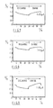
- Figures 7 and 8 are curves showing the charging and discharging characteristics with regard to the batteries of this invention; and
- Figure 9 is of a curve showing the charging and discharging characteristics with regard to a conventional battery.
- The battery of this invention has as its structure a three-layered tablet an arrangement that is formed by the application of pressure to a layered construction of a positive-electrode composition, a separator or solid electrolyte composition, and a negative-electrode composition, the construction being layered in that order. The positive-electrode composition, the separator or the solid electrolyte composition, and the negative-electrode composition are all in the form of powders; an electron-conductive means is provided either in the inside or on the surface of at least one of these two compositions, the positive-electrode composition or the negative-electrode composition.
- First, when a layered tablet is formed by the use of a positive-electrode composition, a separator, and a negative-electrode composition (in the case in which an electrolytic solution is to be contained), the various materials used are described as follows.
- The positive-electrode composition contains a positive active material, an electroconductive material, and a binding agent. The positive active material may be, for examples, oxidizing agents such as manganese dioxide, nickel oxide, tungsten trioxide, lead dioxide, molybdenum trioxide, and the like, of which manganese dioxide and nickel oxide are preferred. The electroconductive material mentioned above refers to an electron-conductive material that is contained in the compositions to ensure their electron conductivity. The electroconductive material may be, for example, acetylene black, plumbago, graphite, carbon black, nickel powder, and the like, of which acetylene black is preferred. The binding agent mentioned above refers to a substance that is added to the compositions to improve the binding properties of the positive active material and the electroconductive material. The binding agent may be, for example, carboxymethylcellulose, polytetrafluoroethylene, salts of carboxymethylcellulose, polyvinyl alcohol, polyethylene, agar, methylcellulose, and the like. The electroconductive material and the binding agent can be present in the positive-electrode composition at the proportions of 3 to 20% by weight.
- The separator can be composed of an electrolyte-supporting material, and can contain a binding agent. The electrolyte-supporting material can be any kind of material with electrical insulating properties. Examples of electrolyte-supporting material that meet such a requirement include silicon dioxide and aluminum oxide. The binding agent can be the same kind of material as used in the positive-electrode composition. The binding agent is preferably used at the proportion of 0 to 20 parts by weight per 100 parts by weight of the electrolyte-supporting material.
- The negative-electrode composition may have the same ingredients as in the positive-electrode composition except that a negative active material is used in place of the positive active material. The negative active material, may be for example hydrogen storage alloys with occluded hydrogen, and examples of these hydrogen storage alloys include TiNi, TiNiB0.01, TiNiMm0.01, LaNi₅, and TiFe. The proportions of electroconductive material and binding agent are the same as those given above for the positive-electrode composition.
- When a layered tablet is formed by use of a positive-electrode composition, a solid electrolyte composition instead of the separator, and a negative-electrode composition, the various materials used are described as follows.
- The positive-electrode composition contains a positive active material, an electroconductive material, a binding agent, and a solid electrolyte. The positive active material, the electroconductive material, and the binding agent can be the same kind of materials as listed above for the positive-electrode composition. The solid electrolyte mentioned above refers to a substance that is contained in the compo sitions to ensure ion conductivity. As the solid electrolyte, there can be used solid electrolyte substances with hydrogen-ion conductivity that are acid hydrates, such as stannic oxide (SnO₂·3H₂O) and antinomyoxide (Sb₂O₅.nH₂O, where n = 3 to 6). The electroconductive material and the binding agent can be present in the positive-electrode composition at the proportions of 3 to 20% by weight, and the solid electrolyte can be present in the positive-electrode composition at the proportion of 10 to 60% by weight.
- The solid electrolyte composition can be composed of a solid electrolyte powder, and can contain a binding agent. The solid electrolyte powder is a powder of the solid electrolyte mentioned above as being contained in the positive-electrolyte composition, and the binding agent can be the same kind of materials as used in the positive-electrode composition. The binding agent is preferably used at the proportion of 0 to 20% parts by weight per 100 parts by weight of the electrolyte-supporting material.
- The negative-electrode composition may have the same ingredients as in the positive-electrode composition described above except that a negative active material is used in place of the positive active material. As the negative active material, there can by used hydrogen storage alloys with occluded hydrogen, and examples of these hydrogen storage alloys include TiNi, TiNiB0.01, TiNiMm0.01, LaNi₅, and TiFe. The proportions of electroconductive material, binding agent, and solid electrolyte are the same as those given above for the positive-electrode composition.
- The electron-conductive means is made of a material with electron conductivity that has in particular the properties of resistance to electrolytes and resistance to electrolytic solutions, and can be present either in the layered tablet or on the surface of the electrode. As the material for this electron-conductive means, there are, for example, metals such as Ni, Au, Pt, Cu, Ag, Ti, W, Zn, Zr, and the like; alloys that contain two or more kinds of these metals; materials the surface of which are coated with one or more kinds of these metals; electroconductive polymers; electroconductive ceramics, or the like. The electron-conductive means can be of any shape such as a net shape, a woven cloth shape, a non-woven cloth shape, a punched plate shape, or an absorbent cotton shape, but it must have holes or irregularities three-dimensionally. Preferred examples of electron-conductive means, include, for example, a Ni net, a Pt net, and the like.
- In the present invention, when the positive-electrode composition, the separator or solid electrolyte composition, and the negative-electrode composition are to be integrally formed by the application of pressure, in the inside or on the surface of at least one of the positive electrode or the negative electrode, there is provided an electron-conductive means to obtain a layered tablet, and this layered tablet is placed inside a battery case to produce a battery.
- The manufacturing process for the battery of this invention will now be described by way of examples only with reference to Figures 1 to 6. The situation when both the positive electrode and the negative electrode contain an electron-conductive means will be described herein, but because the situation in which only one of the electrodes contains this electron-conductive means involves merely the omission of the electron-conductive means from the other electrode, the explanation of the manufacturing process in that situation is omitted here.
- Figure 1 shows a preferred embodiment of the battery of this invention. This battery comprises a positive-
electrode composition 5, a separator orsolid electrolyte composition 6, and a negative-electrode composition 7; electron-conductive means 4 is provided on the surfaces of the positive-electrode composition 5 and the negative-electrode composition 7. - In Figure 2,
reference numeral 1 is a forming mold,reference numeral 2 is a pushing rod for the molding of a powder within the forming mold by the application of pressure, andreference numeral 3 is a holder for the formingmold 1. Thisholder 3 can move upwards and downwards inside the formingmold 1, so the depth of the formingmold 1 can be adjusted thereby. - First, in a forming
mold 1 that is set in this fashion, an electron-conductive means 4 is placed inside, and then the positive-electrode composition 5 in the form of a powder is put inside. The electron-conductive means 4 can also be put inside at the same time as the supplying of the positive-electrode composition 5 in the form of a powder. Then a pushingrod 2 is used to apply pressure, and the positive-electrode composition 5 is levelled out. Next, the separator orsolid electrolyte composition 6 in the form of a powder is put into the formingmold 1 as is shown in Figure 3, and the separator ormold electrolyte composition 6 is levelled out by the application of pressure by pushingrod 2 in the same procedure as is described above. Then the negative-electrode composition 7 in the form of a powder is put into the formingmold 1, after which the electron-conductive means 4 is placed thereon. This situation is shown in Figure 4. The electron-conductive means 4 can be put inside at the same time as the supplying of the negative-electrode composition 7. In addition, it is possible to put the positive-electrode composition 5 containing electron-conductive means 4, the separator orsolid electrolyte composition 6, and the negative-electrode 7 containing the electron-conductive means 4, all in the form of powders, into the formingmold 1 in the opposite order from that given above. - After this, the
powders mold 1 are pressed by the pushingrod 2, so as to form them into one piece. The unit obtained in this way will be called the "layered tablet" below. The situation is illustrated in Figure 5. - If the portion shown as
reference numeral 6 is a powder, that can be used in the manufacturing process, as described above, it can be either a separator or solid electrolyte composition. If the portion shown asreference numeral 6 is a separator, it contains an electrolyte-supporting material, in which the electrolytic solution is held in the spaces between the particles of powder or on the surface of the powder, thereby attaining the objectives of this invention. If the portion shown asreference numeral 6 is a solid electrolyte composition, it contains a solid electrolyte with ion conductivity, thereby attaining the objectives of this invention. - The layered tablet integrally formed as described above is removed from the forming
mold 1, and as is shown in Figure 6, is placed in abattery case 8. In this figure,reference numeral 9 is a current collecting material, andreference numeral 10 is insulating packing. If the portion shown asreference numeral 6 is a separator, it is later immersed in anelectrolytic solution 11 provided in the layered tablet. It is also possible to provide theelectrolytic solution 11 in thebattery case 8 beforehand, or to supply the layered tablet already provided withelectrolytic solution 11 in thebattery case 8. However, when the portion shown asreference numeral 6 is a solid electrolyte composition, it is not necessary to provide theelectrolytic solution 11 described above. - Finally, as is shown in Figure 1, the
cover 12 is attached to thebattery case 8, and both thebattery case 8 and thecover 12 are tightly sealed. - The manufacturing process described above is not limited to batteries in which the electrolytic solution is an aqueous alkaline solution, but can be used to produce batteries that use other kinds of liquid electrolytes such as aqueous acidic solutions and organic solvents, and batteries that use solid electrolytes.
- The invention will be further illustrated by the following examples, but shall not be limited thereto.
- For the positive-electrode composition, 10 parts by weight of γ-manganese dioxide powder, 2 parts by weight of acetylene black as the electroconductive material, and 1 part by weight of carboxymethylcellulose as the binding agent were used in a powdered mixture. First, 200 mg of this powder was put on a Ni net (100 mesh) cut into a disk with a diameter of 15 mm that had already been placed in a forming mold; the whole was pressed slightly from above by a pushing rod.
- For the separator powder, 20 parts by weight of silicon dioxide powder as the electrolyte-supporting material and 1 part by weight of carboxymethylcellulose as the binding agent were used in a powdered mixture. Then 200 mg of this powder was put on top of the positive-electrode composition that had already been placed in the forming mold, and the whole was pressed slightly from above by the pushing rod.
- For the negative-electrode composition, 10 parts by weight of a hydrogenated powder of the hydrogen storage alloy TiNiMm0.01, or 1 part by weight of acetylene black as the electroconductive material, and 1 part by weight of carboxymethylcellulose as the binding agent were used in a powdered mixture. Then, 200 mg of this powder was put on top of the positive-electrode composition and the separator that had already been placed in the forming mold, and a Ni net (100 mesh) cut into a disk with the diameter of 15 mm was placed thereon. The whole was pressed from above at the pressure of 200 kgw/cm², by the pushing rod.
- In this way, a layered tablet for the contents of a battery was obtained. The layered tablet was removed from the forming mold and put into a battery case. To this case, 100 µl of a 30 wt% aqueous solution of potassium hydroxide was added, and the battery case was sealed.
- The battery obtained as described above was tested for its charging and discharging characteristics at 25°C, and the results are shown in Figure 7.
- For the positive-electrode composition, 10 parts by weight of nickel hydroxide, 2 parts by weight of acetylene black as the electroconductive material, and 0.5 part by weight of polytetrafluoroethylene powder as the binding agent were used in a powdered mixture. The mixture was put on a nickel substrate and charged in a 30 wt% aqueous solution of potassium hy droxide. Thereafter, the mixture was removed from the nickel substrate, and pulverized to obtain a powder. Then, 200 mg of this powder was put into a forming mold with an inner diameter of 15 mm that already contained a Ni net (100 mesh) cut into a disk with a diameter of 15 mm. The whole was pressed slightly from above by a pushing rod.
- For the separator powder, 20 parts by weight of α-alumina powder as the electrolyte-supporting material and 1 part by weight of carboxymethylcellulose as the binding agent were used in a powdered mixture. Then, 200 mg of this powder was put on top of the positive-electrode composition that had already been placed in the forming mold; the whole was pressed slightly from above by the pushing rod.
- For the negative-electrode composition, powder prepared in the same way as in Example 1 was used. Then, 200 mg of this powder was put on top of the positive-electrode composition and the separator that had already been placed in the forming mold, and a Ni net (100 mesh) cut into a disk with a diameter of 15 mm was placed thereon; the whole was then pressed from above at the pressure of 200 kgw/cm² by the pushing rod.
- In this way, the contents of a battery were obtained in the form of a layered tablet. This layered tablet was removed from the forming mold and placed in a battery case. To this case was added 100 µl of a 30 wt% aqueous solution of potassium hydroxide, and then the battery case was sealed.
- The battery obtained as described above was tested for its charging and discharging characteristics at 25°C, and the results found are shown in Figure 8.
- A battery was manufactured in the same way as described in Example 1 except that a Ni net was cut into a disk with a diameter of 15 mm as the electron-conductive means was not used when the layered tablet was prepared.
- The battery obtained in this way was tested for its charging and discharging characteristics at 25°C, and the results are shown in Figure 9.
- As seen from the results shown in Figures 7 to 9, according to this invention, it is possible to obtain a battery with small polarizability, in which at least one of the positive-electrode composition and the negative-electrode composition have an electron-conductive means.
- It is understood that various other modifications will be apparent to and can be readily made by those skilled in the art without departing from the scope and spirit of this invention. Accordingly, it is not intended that the scope of the claims appended hereto be limited to the description as set forth herein, but rather that the claims be construed as encompassing all the features of patentable novelty that reside in the present invention, including all features that would be treated as equivalents thereof by those skilled in the art to which this invention pertains.
Claims (4)
Applications Claiming Priority (2)
| Application Number | Priority Date | Filing Date | Title |
|---|---|---|---|
| JP225997/87 | 1987-09-09 | ||
| JP62225997A JPH079811B2 (en) | 1987-09-09 | 1987-09-09 | Battery manufacturing method |
Publications (2)
| Publication Number | Publication Date |
|---|---|
| EP0307209A1 true EP0307209A1 (en) | 1989-03-15 |
| EP0307209B1 EP0307209B1 (en) | 1992-11-25 |
Family
ID=16838174
Family Applications (1)
| Application Number | Title | Priority Date | Filing Date |
|---|---|---|---|
| EP88308322A Expired - Lifetime EP0307209B1 (en) | 1987-09-09 | 1988-09-08 | A battery |
Country Status (4)
| Country | Link |
|---|---|
| US (1) | US5004657A (en) |
| EP (1) | EP0307209B1 (en) |
| JP (1) | JPH079811B2 (en) |
| DE (1) | DE3876183T2 (en) |
Cited By (5)
| Publication number | Priority date | Publication date | Assignee | Title |
|---|---|---|---|---|
| GB2226913A (en) * | 1988-12-14 | 1990-07-11 | Atomic Energy Authority Uk | Electrochemical cell manufacture |
| EP0703633A1 (en) * | 1994-08-17 | 1996-03-27 | AT&T Corp. | Process for activation of metal hydrides |
| WO2000010800A1 (en) * | 1998-08-24 | 2000-03-02 | Henkel Kommanditgesellschaft Auf Aktien | Production of multiphase moulded pieces |
| EP1796187A1 (en) * | 2005-12-09 | 2007-06-13 | BIOTRONIK CRM Patent AG | Apparatus and procedure for the production of electrodes for batteries |
| US8313052B2 (en) | 2005-12-09 | 2012-11-20 | Biotronik Crm Patent Ag | Powder mixture for manufacture of a battery electrode, a respective battery electrode and a method for manufacturing same |
Families Citing this family (9)
| Publication number | Priority date | Publication date | Assignee | Title |
|---|---|---|---|---|
| US5279624A (en) * | 1992-11-27 | 1994-01-18 | Gould Inc. | Solder sealed solid electrolyte cell housed within a ceramic frame and the method for producing it |
| US5378560A (en) * | 1993-01-21 | 1995-01-03 | Fuji Photo Film Co., Ltd. | Nonaqueous secondary battery |
| US5587253A (en) * | 1993-03-05 | 1996-12-24 | Bell Communications Research, Inc. | Low resistance rechargeable lithium-ion battery |
| JP2603188B2 (en) * | 1993-08-25 | 1997-04-23 | 古河電池株式会社 | Hydrogen storage alloy electrode |
| DE4426970A1 (en) * | 1994-07-29 | 1996-02-01 | Varta Batterie | Gas-tight sealed alkaline battery in the form of a button cell |
| US6171723B1 (en) * | 1997-10-10 | 2001-01-09 | 3M Innovative Properties Company | Batteries with porous components |
| JP2009266589A (en) * | 2008-04-24 | 2009-11-12 | Toyota Motor Corp | Solid lithium secondary battery and method of manufacturing the same |
| JP5728659B2 (en) * | 2011-07-29 | 2015-06-03 | パナソニックIpマネジメント株式会社 | Photosensitive electromagnetic wave shielding ink composition, electromagnetic wave shielding cured product, and method for producing electromagnetic wave shielding cured product |
| JP7559706B2 (en) * | 2021-08-23 | 2024-10-02 | トヨタ自動車株式会社 | Anode active material, alkaline storage battery, and method for producing anode active material |
Citations (4)
| Publication number | Priority date | Publication date | Assignee | Title |
|---|---|---|---|---|
| GB1546611A (en) * | 1977-09-02 | 1979-05-23 | Atomic Energy Authority Uk | Electric cells |
| GB1546613A (en) * | 1977-09-02 | 1979-05-23 | Atomic Energy Authority Uk | Electric cells |
| EP0149846A1 (en) * | 1983-12-26 | 1985-07-31 | Kabushiki Kaisha Toshiba | Hermetically sealed metallic oxide-hydrogen battery using hydrogen storage alloy |
| EP0240343A1 (en) * | 1986-04-04 | 1987-10-07 | Sharp Kabushiki Kaisha | Alkaline cell manufacturing method |
Family Cites Families (9)
| Publication number | Priority date | Publication date | Assignee | Title |
|---|---|---|---|---|
| USRE24408E (en) * | 1954-09-02 | 1957-12-17 | silver iodide | |
| US3558360A (en) * | 1968-01-08 | 1971-01-26 | Westinghouse Electric Corp | Fuel cell comprising a stabilized zirconium oxide electrolyte and a doped indium or tin oxide cathode |
| US3660163A (en) * | 1970-06-01 | 1972-05-02 | Catalyst Research Corp | Solid state lithium-iodine primary battery |
| DE2124814A1 (en) * | 1971-05-19 | 1972-12-07 | Bbc Brown Boveri & Cie | Process for the production of a high temperature fuel cell |
| US3988164A (en) * | 1974-04-25 | 1976-10-26 | P. R. Mallory & Co., Inc. | Cathode material for solid state batteries |
| JPS50161636A (en) * | 1974-06-19 | 1975-12-27 | ||
| US3970473A (en) * | 1975-06-12 | 1976-07-20 | General Electric Company | Solid state electrochemical cell |
| JPS6030069B2 (en) * | 1980-11-14 | 1985-07-13 | 工業技術院長 | How to convert chemical energy into electrical energy |
| JPH048899A (en) * | 1990-04-25 | 1992-01-13 | Toyota Autom Loom Works Ltd | Cooling device for electric motor |
-
1987
- 1987-09-09 JP JP62225997A patent/JPH079811B2/en not_active Expired - Fee Related
-
1988
- 1988-09-08 DE DE8888308322T patent/DE3876183T2/en not_active Expired - Fee Related
- 1988-09-08 EP EP88308322A patent/EP0307209B1/en not_active Expired - Lifetime
-
1989
- 1989-12-12 US US07/449,450 patent/US5004657A/en not_active Expired - Lifetime
Patent Citations (4)
| Publication number | Priority date | Publication date | Assignee | Title |
|---|---|---|---|---|
| GB1546611A (en) * | 1977-09-02 | 1979-05-23 | Atomic Energy Authority Uk | Electric cells |
| GB1546613A (en) * | 1977-09-02 | 1979-05-23 | Atomic Energy Authority Uk | Electric cells |
| EP0149846A1 (en) * | 1983-12-26 | 1985-07-31 | Kabushiki Kaisha Toshiba | Hermetically sealed metallic oxide-hydrogen battery using hydrogen storage alloy |
| EP0240343A1 (en) * | 1986-04-04 | 1987-10-07 | Sharp Kabushiki Kaisha | Alkaline cell manufacturing method |
Cited By (10)
| Publication number | Priority date | Publication date | Assignee | Title |
|---|---|---|---|---|
| GB2226913A (en) * | 1988-12-14 | 1990-07-11 | Atomic Energy Authority Uk | Electrochemical cell manufacture |
| US5030523A (en) * | 1988-12-14 | 1991-07-09 | United Kingdom Atomic Energy Authority | Electrochemical cell manufacture |
| GB2226913B (en) * | 1988-12-14 | 1992-09-30 | Atomic Energy Authority Uk | Electrochemical cell manufacture |
| EP0703633A1 (en) * | 1994-08-17 | 1996-03-27 | AT&T Corp. | Process for activation of metal hydrides |
| US5560752A (en) * | 1994-08-17 | 1996-10-01 | Lucent Technologies Inc. | Process for activation of metal hydrides |
| WO2000010800A1 (en) * | 1998-08-24 | 2000-03-02 | Henkel Kommanditgesellschaft Auf Aktien | Production of multiphase moulded pieces |
| EP1796187A1 (en) * | 2005-12-09 | 2007-06-13 | BIOTRONIK CRM Patent AG | Apparatus and procedure for the production of electrodes for batteries |
| US7758782B2 (en) | 2005-12-09 | 2010-07-20 | Biotronik Crm Patent Ag | Method and device for producing electrodes for batteries |
| US8210838B2 (en) | 2005-12-09 | 2012-07-03 | Biotronik Crm Patent Ag | Method and device for producing electrodes for batteries |
| US8313052B2 (en) | 2005-12-09 | 2012-11-20 | Biotronik Crm Patent Ag | Powder mixture for manufacture of a battery electrode, a respective battery electrode and a method for manufacturing same |
Also Published As
| Publication number | Publication date |
|---|---|
| DE3876183D1 (en) | 1993-01-07 |
| DE3876183T2 (en) | 1993-04-01 |
| JPS6471067A (en) | 1989-03-16 |
| EP0307209B1 (en) | 1992-11-25 |
| US5004657A (en) | 1991-04-02 |
| JPH079811B2 (en) | 1995-02-01 |
Similar Documents
| Publication | Publication Date | Title |
|---|---|---|
| US5626988A (en) | Sealed rechargeable cells containing mercury-free zinc anodes, and a method of manufacture | |
| US3956018A (en) | Primary electric current-producing dry cell using a (CFx)n cathode and an aqueous alkaline electrolyte | |
| CA1311519C (en) | Secondary battery | |
| US3880672A (en) | Battery barrier and battery | |
| CA1133050A (en) | Rechargeable electrical storage battery with zinc anode and aqueous alkaline electrolyte | |
| US3870564A (en) | Alkaline cell | |
| US5462821A (en) | Gallium based active material for the negative electrode, a negative electrode using the same, and batteries using said negative electrode | |
| EP0307209A1 (en) | A battery | |
| WO1997017737A1 (en) | Rechargeable alkaline cells containing zinc anodes without added mercury | |
| JPH04137368A (en) | Nickel-hydrogen storage battery and its manufacture | |
| WO2001018897A1 (en) | Rechargeable nickel-zinc cells | |
| US5690799A (en) | Hydrogen-occluding alloy and hydrogen-occluding alloy electrode | |
| CN1114232C (en) | Hydrogen-absorbing alloy for alkaline storage battery and alkaline storage battery made of the alloy | |
| JPS63308868A (en) | Secondary cell | |
| JP4253172B2 (en) | Sealed nickel zinc primary battery | |
| JP3475652B2 (en) | Negative electrode for alkaline storage battery and battery using the same | |
| JPH06310125A (en) | Negative electrode for lithium secondary battery | |
| JP3049854B2 (en) | Sealed battery | |
| JP2004502279A (en) | Electrochemical cell with anode containing sulfur | |
| JP3115574B2 (en) | Battery | |
| JP2001283902A (en) | Alkaline storage battery | |
| JPH1050299A (en) | Non-aqueous electrolyte secondary battery | |
| JP3587213B2 (en) | Negative electrode active material for air-Ga primary battery and air-Ga primary battery using the same | |
| JP3316687B2 (en) | Nickel-metal hydride storage battery | |
| JPH09171837A (en) | Nickel-hydrogen secondary battery |
Legal Events
| Date | Code | Title | Description |
|---|---|---|---|
| PUAI | Public reference made under article 153(3) epc to a published international application that has entered the european phase |
Free format text: ORIGINAL CODE: 0009012 |
|
| 17P | Request for examination filed |
Effective date: 19880923 |
|
| AK | Designated contracting states |
Kind code of ref document: A1 Designated state(s): DE FR GB |
|
| 17Q | First examination report despatched |
Effective date: 19901203 |
|
| GRAA | (expected) grant |
Free format text: ORIGINAL CODE: 0009210 |
|
| AK | Designated contracting states |
Kind code of ref document: B1 Designated state(s): DE FR GB |
|
| ET | Fr: translation filed | ||
| REF | Corresponds to: |
Ref document number: 3876183 Country of ref document: DE Date of ref document: 19930107 |
|
| PLBE | No opposition filed within time limit |
Free format text: ORIGINAL CODE: 0009261 |
|
| STAA | Information on the status of an ep patent application or granted ep patent |
Free format text: STATUS: NO OPPOSITION FILED WITHIN TIME LIMIT |
|
| 26N | No opposition filed | ||
| REG | Reference to a national code |
Ref country code: GB Ref legal event code: IF02 |
|
| PGFP | Annual fee paid to national office [announced via postgrant information from national office to epo] |
Ref country code: GB Payment date: 20020904 Year of fee payment: 15 |
|
| PGFP | Annual fee paid to national office [announced via postgrant information from national office to epo] |
Ref country code: FR Payment date: 20020910 Year of fee payment: 15 |
|
| PGFP | Annual fee paid to national office [announced via postgrant information from national office to epo] |
Ref country code: DE Payment date: 20020911 Year of fee payment: 15 |
|
| PG25 | Lapsed in a contracting state [announced via postgrant information from national office to epo] |
Ref country code: GB Free format text: LAPSE BECAUSE OF NON-PAYMENT OF DUE FEES Effective date: 20030908 |
|
| PG25 | Lapsed in a contracting state [announced via postgrant information from national office to epo] |
Ref country code: DE Free format text: LAPSE BECAUSE OF NON-PAYMENT OF DUE FEES Effective date: 20040401 |
|
| GBPC | Gb: european patent ceased through non-payment of renewal fee |
Effective date: 20030908 |
|
| PG25 | Lapsed in a contracting state [announced via postgrant information from national office to epo] |
Ref country code: FR Free format text: LAPSE BECAUSE OF NON-PAYMENT OF DUE FEES Effective date: 20040528 |
|
| REG | Reference to a national code |
Ref country code: FR Ref legal event code: ST |