EP0307112B1 - Geflochtenes Lager und Herstellungsverfahren für ein geflochtenes Lager - Google Patents
Geflochtenes Lager und Herstellungsverfahren für ein geflochtenes Lager Download PDFInfo
- Publication number
- EP0307112B1 EP0307112B1 EP88307874A EP88307874A EP0307112B1 EP 0307112 B1 EP0307112 B1 EP 0307112B1 EP 88307874 A EP88307874 A EP 88307874A EP 88307874 A EP88307874 A EP 88307874A EP 0307112 B1 EP0307112 B1 EP 0307112B1
- Authority
- EP
- European Patent Office
- Prior art keywords
- mandrel
- bearing
- cylindrical
- strands
- braid layer
- Prior art date
- Legal status (The legal status is an assumption and is not a legal conclusion. Google has not performed a legal analysis and makes no representation as to the accuracy of the status listed.)
- Expired - Lifetime
Links
Images


Classifications
-
- D—TEXTILES; PAPER
- D04—BRAIDING; LACE-MAKING; KNITTING; TRIMMINGS; NON-WOVEN FABRICS
- D04C—BRAIDING OR MANUFACTURE OF LACE, INCLUDING BOBBIN-NET OR CARBONISED LACE; BRAIDING MACHINES; BRAID; LACE
- D04C3/00—Braiding or lacing machines
- D04C3/48—Auxiliary devices
-
- B—PERFORMING OPERATIONS; TRANSPORTING
- B29—WORKING OF PLASTICS; WORKING OF SUBSTANCES IN A PLASTIC STATE IN GENERAL
- B29C—SHAPING OR JOINING OF PLASTICS; SHAPING OF MATERIAL IN A PLASTIC STATE, NOT OTHERWISE PROVIDED FOR; AFTER-TREATMENT OF THE SHAPED PRODUCTS, e.g. REPAIRING
- B29C70/00—Shaping composites, i.e. plastics material comprising reinforcements, fillers or preformed parts, e.g. inserts
- B29C70/04—Shaping composites, i.e. plastics material comprising reinforcements, fillers or preformed parts, e.g. inserts comprising reinforcements only, e.g. self-reinforcing plastics
- B29C70/06—Fibrous reinforcements only
- B29C70/10—Fibrous reinforcements only characterised by the structure of fibrous reinforcements, e.g. hollow fibres
- B29C70/16—Fibrous reinforcements only characterised by the structure of fibrous reinforcements, e.g. hollow fibres using fibres of substantial or continuous length
- B29C70/22—Fibrous reinforcements only characterised by the structure of fibrous reinforcements, e.g. hollow fibres using fibres of substantial or continuous length oriented in at least two directions forming a two-dimensional [2D] structure
- B29C70/222—Fibrous reinforcements only characterised by the structure of fibrous reinforcements, e.g. hollow fibres using fibres of substantial or continuous length oriented in at least two directions forming a two-dimensional [2D] structure the structure being shaped to form a three dimensional configuration
-
- B—PERFORMING OPERATIONS; TRANSPORTING
- B29—WORKING OF PLASTICS; WORKING OF SUBSTANCES IN A PLASTIC STATE IN GENERAL
- B29C—SHAPING OR JOINING OF PLASTICS; SHAPING OF MATERIAL IN A PLASTIC STATE, NOT OTHERWISE PROVIDED FOR; AFTER-TREATMENT OF THE SHAPED PRODUCTS, e.g. REPAIRING
- B29C70/00—Shaping composites, i.e. plastics material comprising reinforcements, fillers or preformed parts, e.g. inserts
- B29C70/04—Shaping composites, i.e. plastics material comprising reinforcements, fillers or preformed parts, e.g. inserts comprising reinforcements only, e.g. self-reinforcing plastics
- B29C70/28—Shaping operations therefor
- B29C70/30—Shaping by lay-up, i.e. applying fibres, tape or broadsheet on a mould, former or core; Shaping by spray-up, i.e. spraying of fibres on a mould, former or core
- B29C70/32—Shaping by lay-up, i.e. applying fibres, tape or broadsheet on a mould, former or core; Shaping by spray-up, i.e. spraying of fibres on a mould, former or core on a rotating mould, former or core
-
- D—TEXTILES; PAPER
- D04—BRAIDING; LACE-MAKING; KNITTING; TRIMMINGS; NON-WOVEN FABRICS
- D04C—BRAIDING OR MANUFACTURE OF LACE, INCLUDING BOBBIN-NET OR CARBONISED LACE; BRAIDING MACHINES; BRAID; LACE
- D04C1/00—Braid or lace, e.g. pillow-lace; Processes for the manufacture thereof
- D04C1/06—Braid or lace serving particular purposes
-
- F—MECHANICAL ENGINEERING; LIGHTING; HEATING; WEAPONS; BLASTING
- F16—ENGINEERING ELEMENTS AND UNITS; GENERAL MEASURES FOR PRODUCING AND MAINTAINING EFFECTIVE FUNCTIONING OF MACHINES OR INSTALLATIONS; THERMAL INSULATION IN GENERAL
- F16C—SHAFTS; FLEXIBLE SHAFTS; ELEMENTS OR CRANKSHAFT MECHANISMS; ROTARY BODIES OTHER THAN GEARING ELEMENTS; BEARINGS
- F16C17/00—Sliding-contact bearings for exclusively rotary movement
- F16C17/10—Sliding-contact bearings for exclusively rotary movement for both radial and axial load
-
- F—MECHANICAL ENGINEERING; LIGHTING; HEATING; WEAPONS; BLASTING
- F16—ENGINEERING ELEMENTS AND UNITS; GENERAL MEASURES FOR PRODUCING AND MAINTAINING EFFECTIVE FUNCTIONING OF MACHINES OR INSTALLATIONS; THERMAL INSULATION IN GENERAL
- F16C—SHAFTS; FLEXIBLE SHAFTS; ELEMENTS OR CRANKSHAFT MECHANISMS; ROTARY BODIES OTHER THAN GEARING ELEMENTS; BEARINGS
- F16C33/00—Parts of bearings; Special methods for making bearings or parts thereof
- F16C33/02—Parts of sliding-contact bearings
- F16C33/04—Brasses; Bushes; Linings
- F16C33/20—Sliding surface consisting mainly of plastics
- F16C33/201—Composition of the plastic
-
- F—MECHANICAL ENGINEERING; LIGHTING; HEATING; WEAPONS; BLASTING
- F16—ENGINEERING ELEMENTS AND UNITS; GENERAL MEASURES FOR PRODUCING AND MAINTAINING EFFECTIVE FUNCTIONING OF MACHINES OR INSTALLATIONS; THERMAL INSULATION IN GENERAL
- F16C—SHAFTS; FLEXIBLE SHAFTS; ELEMENTS OR CRANKSHAFT MECHANISMS; ROTARY BODIES OTHER THAN GEARING ELEMENTS; BEARINGS
- F16C33/00—Parts of bearings; Special methods for making bearings or parts thereof
- F16C33/02—Parts of sliding-contact bearings
- F16C33/04—Brasses; Bushes; Linings
- F16C33/20—Sliding surface consisting mainly of plastics
- F16C33/208—Methods of manufacture, e.g. shaping, applying coatings
-
- F—MECHANICAL ENGINEERING; LIGHTING; HEATING; WEAPONS; BLASTING
- F16—ENGINEERING ELEMENTS AND UNITS; GENERAL MEASURES FOR PRODUCING AND MAINTAINING EFFECTIVE FUNCTIONING OF MACHINES OR INSTALLATIONS; THERMAL INSULATION IN GENERAL
- F16C—SHAFTS; FLEXIBLE SHAFTS; ELEMENTS OR CRANKSHAFT MECHANISMS; ROTARY BODIES OTHER THAN GEARING ELEMENTS; BEARINGS
- F16C33/00—Parts of bearings; Special methods for making bearings or parts thereof
- F16C33/02—Parts of sliding-contact bearings
- F16C33/04—Brasses; Bushes; Linings
- F16C33/24—Brasses; Bushes; Linings with different areas of the sliding surface consisting of different materials
-
- F—MECHANICAL ENGINEERING; LIGHTING; HEATING; WEAPONS; BLASTING
- F16—ENGINEERING ELEMENTS AND UNITS; GENERAL MEASURES FOR PRODUCING AND MAINTAINING EFFECTIVE FUNCTIONING OF MACHINES OR INSTALLATIONS; THERMAL INSULATION IN GENERAL
- F16C—SHAFTS; FLEXIBLE SHAFTS; ELEMENTS OR CRANKSHAFT MECHANISMS; ROTARY BODIES OTHER THAN GEARING ELEMENTS; BEARINGS
- F16C33/00—Parts of bearings; Special methods for making bearings or parts thereof
- F16C33/02—Parts of sliding-contact bearings
- F16C33/04—Brasses; Bushes; Linings
- F16C33/28—Brasses; Bushes; Linings with embedded reinforcements shaped as frames or meshed materials
-
- B—PERFORMING OPERATIONS; TRANSPORTING
- B29—WORKING OF PLASTICS; WORKING OF SUBSTANCES IN A PLASTIC STATE IN GENERAL
- B29C—SHAPING OR JOINING OF PLASTICS; SHAPING OF MATERIAL IN A PLASTIC STATE, NOT OTHERWISE PROVIDED FOR; AFTER-TREATMENT OF THE SHAPED PRODUCTS, e.g. REPAIRING
- B29C2793/00—Shaping techniques involving a cutting or machining operation
- B29C2793/009—Shaping techniques involving a cutting or machining operation after shaping
-
- B—PERFORMING OPERATIONS; TRANSPORTING
- B29—WORKING OF PLASTICS; WORKING OF SUBSTANCES IN A PLASTIC STATE IN GENERAL
- B29C—SHAPING OR JOINING OF PLASTICS; SHAPING OF MATERIAL IN A PLASTIC STATE, NOT OTHERWISE PROVIDED FOR; AFTER-TREATMENT OF THE SHAPED PRODUCTS, e.g. REPAIRING
- B29C70/00—Shaping composites, i.e. plastics material comprising reinforcements, fillers or preformed parts, e.g. inserts
- B29C70/04—Shaping composites, i.e. plastics material comprising reinforcements, fillers or preformed parts, e.g. inserts comprising reinforcements only, e.g. self-reinforcing plastics
- B29C70/28—Shaping operations therefor
- B29C70/54—Component parts, details or accessories; Auxiliary operations, e.g. feeding or storage of prepregs or SMC after impregnation or during ageing
- B29C70/545—Perforating, cutting or machining during or after moulding
-
- F—MECHANICAL ENGINEERING; LIGHTING; HEATING; WEAPONS; BLASTING
- F16—ENGINEERING ELEMENTS AND UNITS; GENERAL MEASURES FOR PRODUCING AND MAINTAINING EFFECTIVE FUNCTIONING OF MACHINES OR INSTALLATIONS; THERMAL INSULATION IN GENERAL
- F16C—SHAFTS; FLEXIBLE SHAFTS; ELEMENTS OR CRANKSHAFT MECHANISMS; ROTARY BODIES OTHER THAN GEARING ELEMENTS; BEARINGS
- F16C2208/00—Plastics; Synthetic resins, e.g. rubbers
- F16C2208/20—Thermoplastic resins
- F16C2208/40—Imides, e.g. polyimide [PI], polyetherimide [PEI]
-
- F—MECHANICAL ENGINEERING; LIGHTING; HEATING; WEAPONS; BLASTING
- F16—ENGINEERING ELEMENTS AND UNITS; GENERAL MEASURES FOR PRODUCING AND MAINTAINING EFFECTIVE FUNCTIONING OF MACHINES OR INSTALLATIONS; THERMAL INSULATION IN GENERAL
- F16C—SHAFTS; FLEXIBLE SHAFTS; ELEMENTS OR CRANKSHAFT MECHANISMS; ROTARY BODIES OTHER THAN GEARING ELEMENTS; BEARINGS
- F16C2220/00—Shaping
- F16C2220/28—Shaping by winding impregnated fibres
Definitions
- the invention relates generally to bearings and deals more particularly with braided bearings having an integrally connected flange.
- Bearings embodying the present invention may be used in aircraft, for example, to guide control shafts for jet engine vanes because such bearings are light-weight and may be self-lubricating. Such bearings also may be used in a marine environment, with hinges of doors of military landing crafts or ships, and latching mechanism for watertight doors because such bearings are resistant to salt water. In any application of a braided bearing embodying the present invention, the bearing may be exposed to rotational, oscillatory, or reciprocal stresses or a combination of such stresses transmitted by an associated shaft or other part.
- U.S. Patent No. 3,030,248 to Runton An example of a flanged bearing is disclosed in U.S. Patent No. 3,030,248 to Runton, and takes the form of a washer punched or cut from a sheet of fabric.
- Another bearing of the same general type is disclosed in U.S. Patent No. 2,128,087 to Gatke, and takes the form of a cylindrical bushing made by rolling a sheet of fabric or coiling a strip of fabric into the shape of a cylinder.
- either mode of construction disclosed in '087 leaves an undesirable seam.
- it is possible to bond the cylindrical bushing of '087 to the washer of '248 by epoxy to make a flanged bushing the epoxy bond is not strong or durable enough for some applications.
- Another way to make a flanged bushing is to begin with an elongated cylindrical journal bushing of the type discussed in '087 and then make longitudinal cuts in an end portion of the cylinder to form strips which remain attached at one end to the remainder of the cylinder. Then these strips may be bent radially outward, and rigidified in the radial position with a thermosetting, thermoplastic or other type resin.
- this process takes several steps, and the bushing's flange strength is reduced by cuts in the fiber, resulting in discontinuous fibers connecting the flange to the cylindrical journal.
- a flanged, cylindrical, fluid or electrical conduit comprising braided fibers and a hardened resin polyimide is disclosed in U.S. Patent 3,586,058 to Ahrens, as well as the method for making the conduit comprising braiding, immersion in resin, wrapping with tape, curing and postcuring.
- the Ahrens patent is not directed towards bearing technology and, therefore, provides no guidance as to the type of fiber, fiber configuration, resin selection or selection of any other parameters which would be useful in bearing design.
- a shaped, braided hollow body having a varying cross-section is described in U.S. Patent No. 4,228,207.
- bearings used in aircraft and marine environments consist of powdered carbon which has been compressed into a hollow, cylindrical shape and encased in an outer metal jacket.
- the jacket may also include a collar or flange used to position the cylindrical body in a housing and absorb axial loads or thrusts.
- bushings in a jet engine There are often hundreds of bushings in a jet engine, and these carbon type bushings have an appreciable size and weight in the aircraft in which they are used.
- the bushing for use as a bearing to guide an associated first part for movement and relative to a second part includes a hollow portion that has a longitudinal axis and that has inner and outer surfaces adapted to receive the first and second parts, respectively.
- a flanged portion which is integral and continuous with the hollow portion is formed to extend outwardly from a hollow outer surface. Both the hollow portion and the flanged portion are formed from a braid layer woven with a plurality of strands substantially parallel to the longitudinal axis. Also included is a means for rigidifying the woven braid.
- the method for making a flanged bushing includes the steps of weaving a plurality of strands over a mandrel forming a continuously woven braid layer with a plurality of the strands substantially parallel to a woven braid longitudinal axis.
- the mandrel has a first portion which extends outward beyond a second portion.
- a preferred method for making a flanged bearing includes the steps of weaving a plurality of strands to form continuous first and second woven braid layers that are concentric about a longitudinal axis.
- the braid layers are woven with a plurality of the strands substantially parallel to the woven braid longitudinal axis and such that the first and second woven braid layers are continuous at a peripheral edge thereof.
- Also included in the present method is the step of forming a flange at the braid layer peripheral edge with the flange extending outwardly from the woven braid layers, and the step of applying a means for rigidifying the woven braid to form a bearing preform.
- a further step is configuring the bearing preform into a bearing.
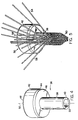
- Fig. 1 is a perspective view of a flanged bushing type bearing embodying the present invention.
- Fig. 2 is a sectional view of the flanged bushing of Fig. 1.
- Fig. 3 is a sectional view of a bearing assembly embodying the invention, which assembly comprises the flanged bushing of Fig. 1 embedded in a housing and engaged by a shaft.
- Fig. 4 is a perspective view of a mandrel used to form the bushing of Fig. 1.
- Fig. 5 diagramatically show a braid progressively being woven onto the mandrel of Fig. 4.
- Fig. 6 and 7 diagramatically show the braid of Fig. 5 woven completely onto the mandrel of Fig. 4 and clamped.
- Fig. 8 is a simplified sectional view of a portion of an apparatus used in pressing bushings of the prior art.
- Fig. 9. is a sectional illustration of a portion of an alternative embodiment of the bearing of Fig. 1.
- Figs. 1 and 2 show a plain, flanged bushing type bearing 10 embodying the present invention.
- the bushing 10 includes a hollow, cylindrical journal portion or sleeve 12 and an integral, radially extending, flange portion 14 at one end of the sleeve.
- the bushing 10 may be used to guide a shaft which is rotating, oscillating, reciprocating or otherwise moving within the bushing 10 in contact with an inner surface 16.
- the bushing comprises a plurality of strands woven together into a braid forming a braid layer 17 with strands woven either at an angle or parallel to a longitudinal bearing axis 18.
- Each strand comprises a plurality of individual fibers or filaments.
- strands 20 and 22 are disposed at an angle with respect to axis 18, while strand 24 remains substantially parallel thereto.
- a bearing provided according to the present invention is characterized by strands which maintain their relative orientation, even when finally configured as a flanged portion. Therefore, in Fig. 1, strand 24 continues through the flanged portion 14 with substantially the same relationship to strand 20 and 22 as it had in the cylindrical journal portion.
- the flange portion extends outwardly from the axis 18 by approximated 90° so that strand 24 extends radially from the axis.
- the number of externally visible axial strands has been exaggerated.
- a strand may comprise fiberglass, polyester, teflon or Kevlar, a product of E. I. duPont Company.
- the strands may comprise nylon, cotton, ceramic, metallic braid, flax or other material, and the resin may be made of polyester, epoxy, or other thermosetting or thermoplastic material.
- the strands may be selected from known materials already impregnated with resin (prepreg). Those skilled in the art will note that the number of fibers comprising an individual strand is selected based on the application of the bearing.
- a flanged bushing 10 may be used in conjunction with a shaft made of a variety of materials also durable at high temperatures, such as Inconel, a metal commonly used in the aircraft industry, or titanium coated with nickel by the electroless process.
- the titanium is ordinarily coated with nickel, at least for parts which are commonly subject to friction, such as a shaft, because titanium alone wears when exposed to such forces.
- a flanged bearing provided according to the present invention is suitable for aircraft applications because it is lightweight, strong, and thin-walled and is compatible with other composite elements.
- Fig. 3 shows a bearing assembly generally designated 26 comprising the bushing 10 situated in a housing 28 and in receipt of a shaft 30, the shaft being connected to a jet engine vane 32.
- the flange provides a bearing surface for a related abutting part, such as the vane 32.
- the bushing 10 may be received by or attached to the housing in a variety of ways.
- the vane bears on an outer surface of the flange 14 so the bushing may be loosely fit in a bore 34 in the housing.
- the bushing 10 may be further secured to the housing by an appropriate adhesive applied between the flange and the housing. Instead of or in addition to the adhesive, the bushing 10 may be pressed into the housing and secured by means of an interference fit. Alternatively, it is possible to key the bushing into the housing.
- the bushing 10 may cause less wear on the housing than would a bushing having a metal jacket, especially if the strand and resin material of the bushing 10 are self-lubricating.
- a braiding mandrel 36 which includes a cylindrical shank portion 38 having bottom end surface 40 and a cylindrical shoulder portion 42 attached at the end of the shank portion opposite the end surface 40, the shoulder 42 being broader than the shank and having a bevel 44.
- the shoulder includes a flat end surface 46 extending radially outward from the shank, and another end surface 48 which other end surface may be involved in the braiding process.
- the mandrel serves as an armature upon which to weave the individual strands or bundles and includes an aperture 50 for receiving a rod (not shown) which rod is used to move the mandrel during the braiding process, the mandrel being removed in a subsequent fabrication step by means of a mold release agent, such as silicon applied to the surface of the mandrel.
- a mold release agent such as silicon applied to the surface of the mandrel.
- a bushing provided according to the present invention comprises a plurality of strands woven both at an angle to a longitudinal axis 52 of the mandrel and strands parallel to that axis.
- the individual strands maintain their geometric relationships as the woven braids encompass the shank 38 and shoulder 42 of the mandrel illustrated in Fig. 6.
- Longitudinal or axial strands provide additional strength to the bushing along the longitudinal axis and substantially increase the strength of the bushing at the junction of the flange and sleeve. Therefore, the strength of the bushing flange is considerably increased over known braided bearings.
- Fig. 5 diagramatically shows strands progressively being woven onto the mandrel 36, and based on the orientation of the mandrel, each braid is woven upwardly.
- Any one of the various well known braiding or weaving techniques can be utilized to weave the braids of the present invention.
- spools of fibre are arranged on at least one ring around a mandrel and strands leads of the fibers, such as the crossing strands 54, 56 and axial strand 58, are woven to form a braid layer 60.
- the bottom end 40 of the shank of the mandrel is inserted into the braid layer, and the weaving may be continued longitudinally to cover the shank as shown in Fig. 6, continued radially outward to cover the end surface 46 of the shoulder and continued longitudinal upward to ultimately cover at least a portion of the cylindrical surface of the shoulder 42 with a layer of woven braid.
- the woven braid layer 60 is clamped by a ring 62 onto the shoulder.
- the woven braid covering the shank and the end surface may effectively retain their shape until the clamping ring is applied. Furthermore, with the complete covering of braid on the cylindrical surface and a covering on much of the end surface, the braid may be cut above the end surface, and a resin applied to the braid and cured with or without utilizing the clamping ring. Those skilled in the art will note that the woven braid may be folded back upon itself in a conventional manner and continued forming an additional layer of braid.
- the woven braid must be resin impreganted.
- the woven braid layer is clamped, cut above the shoulder, and impregnated with resin. If a polyimide resin has been used, the resin impregnated braid and mandrel are subjected to a "B-stage" process to produced a preform whereby the resin impregated braid is force dried for fifteen minutes each at 93°, 121° and 135°C (200°, 250°, and 275°F).
- the resin is cured by heating the resin impregnated braid above 204°C (400°F) at 13.79 x 10⁶Nm ⁇ 2 (2,000 psi) of pressure in a press to debulk the preform and cause the resin impregnated braid to rigidify.
- the preform is cut near the peripheries of the end surfaces of the mandrel and the ring and the excess braid removed.
- the rigidified braid preform is post cured for approximately three hours.
- the rigidified braid is machined at the peripheries of the end surfaces to form the bottom of the sleeve 12 and the outer periphery of the flange 14, respectively.
- a flanged conduit is formed by first weaving a braid over a mandrel having a cylindrical shank and detachable, conically-shaped head. Then, this head is replaced with a flat head which abuts and flattens the portion of the braid which was previously formed over the conical head, and a resin is applied to the braid to stiffen it.
- the dimensions of the cylindrical portion 12 and the flange 14 may be controlled by providing a braiding mandrel with corresponding shank and shoulder dimensions, and because the cylindrical body 12 of the bushing 10 comprises a braid, the cylindrical body 12 may have virtually unlimited length possible. Moreover, with a bearing provided according to the present invention the bearing journal to flange dimensional aspect ratios are greatly increased due to the strengthened journal to flange interface.
- FIG. 8 illustrates, in section, a bushing preform 64 which is pressed in an apparatus 66 having a ram portion 68, a center pin 70 and a central plug portion 72.
- the ram exerts pressure along a longitudinal axis 74 of the preform displacing a portion of the preform radially outward.
- the braid layer is woven with a plurality of axial strands. During the process of displacing the single braid layer, the alignment of all strands, including any axial strands is disturbed, crossing one another and otherwise becoming random in orientation.
- Fig. 9 is a sectional illustration of an alternative embodiment 76 of the bushing of Figure 1. Without the use of a mandrel, the weaving method and apparatus used in the formation of the bushing 10 of Figure 1 will weave a substantially cylindrical braided layer generally indicated at 78. After the first layer of the braid has been woven a selected length about an axis 80, an outermost portion of the first braid layer is folded back over on itself, such that a second braid layer 82 is formed exterior to the first. This second braided layer is continuous and integral with the first and is joined therewith about a peripheral edge 84.
- the weaving process is halted and a flange 86 is formed by folding or otherwise outwardly displacing a portion of the braided layers including peripheral edge 84.
- the size of the flange is dependent on the amount of braided layer displacement and can be adjusted according to the bushing application.
- the woven braided layers with a flange forms a preform and can be processed with a rigidifying means such as a resin or other rigidifying means in a manner similar to that of bushing 10 of Figure 1.
- a multiple braid layer which is continuous at a peripheral edge maintains the relative orientation of the strands during the flange formation process.
- the outer braid layer formed by back braiding not only provides additional strength but prevents distortion of the strands and loss of relative orientation during the flange formation process.
- the braided layer is woven with plurality of strands substantially parallel to the longitudinal axis of the bushing in the manner described hereinabove.
- axial strands transverse the length of the braid layer 78, extend radially outward from and back toward axis 80 in the flange 86, and longitudinally traverse along braid layer 82.
Landscapes
- Engineering & Computer Science (AREA)
- General Engineering & Computer Science (AREA)
- Mechanical Engineering (AREA)
- Textile Engineering (AREA)
- Chemical & Material Sciences (AREA)
- Composite Materials (AREA)
- Manufacturing & Machinery (AREA)
- Sliding-Contact Bearings (AREA)
Claims (7)
- Ein Lager (10) zur Verwendung bei der beweglichen Führung eines zugeordneten ersten Teils (29) relativ zu einem zweiten Teil (26), umfassend einen hohlzylindrischen Bereich (12), der symmetrisch um eine Längsachse (18) des Lagers angeordnet ist und einen konstanten Durchmesser hat, der eine sich nicht ändernde Querschnittsform definiert, wobei der hohlzylindrische Bereich (12) entlang seiner Länge eine für die Aufnahme entweder des ersten oder des zweiten Teils ausgebildete Innenfläche und eine für das Zusammenwirken mit dem jeweils anderen Teil ausgebildete Außenfläche hat; einen zylindrischen Flanschbereich (14), der einstückig mit dem hohlzylindrischen Bereich (12) verbunden ist und sich von der im wesentlichen senkrecht dazu verlaufenden Außenfläche des Hohlbereichs radial nach außen erstreckt, wobei der hohlzylindrische Bereich und der Flanschbereich aus einer Flechtschicht (17) gebildet sind, dadurch gekennzeichnet, daß die Flechtschicht eine Vielzahl von damit einstückig gebildeten axialen Litzen (24) hat, die um den hohlzylindrischen Bereich herum voneinander beabstandet sind und sich in bezug auf die Längsachse (18) im wesentlichen parallel erstrecken; daß Bereiche dieser Vielzahl von axialen Litzen von der Außenfläche des hohlzylindrischen Bereichs senkrecht nach außen und in den Flanschbereich hinein gerichtet sind, so daß jede dieser axialen Litzen in dem Flanschbereich von dem hohlzylindrischen Bereich aus radial nach außen gerichtet ist; daß die Flechtschicht ferner eine Vielzahl von Querlitzen (54) hat, die mit der Vielzahl von axialen Litzen verflochten sind; und daß die Flechtschicht mit einem Harzmittel imprägniert ist, um die sich nicht verändernde Konfiguration des hohlzylindrischen Bereichs und die dazu senkrechte Ausrichtung des Flanschbereichs fest beizubehalten.
- Verfahren zur Herstellung eines Lagers (10) mit einem Hohlbereich (12) und einem daran anschließenden Flanschbereich (14) zum beweglichen Führen eines zugeordneten ersten Teils (29) relativ zu einem zweiten Teil (26), gekennzeichnet durch folgende Verfahrensschritte:
Bereitstellung eines Dorns (36), der eine Längsachse (52) und einen zylindrischen Schaftbereich (38) hat, der ein freies Ende (40) und ein mit einem Schulterbereich verbundenes gegenüberliegendes Ende hat;
Anordnen des zylindrischen Schaftbereichs und des zylindrischen Schulterbereichs konzentrisch um die Längsachse (52) des Dorns und Ausbildung des zylindrischen Schulterbereichs mit einem Durchmesser, der breiter ist als jener des Schaftbereichs, so daß der Schulterbereich und der Schaftbereich durch eine sich von dem zylindrischen Schaftbereich aus radial nach außen und senkrecht erstreckende flache Endfläche miteinander verbunden sind;
Flechten einer Vielzahl von Litzen (24) über den Dorn (36) zur Bildung eines von dem Dorn getragenen Vorformlings (68), indem eine Vielzahl von axialen Litzen vorgesehen und deren jede entlang der Außenfläche des zylindrischen Schaftbereichs im wesentlichen parallel zur Längsachse (52) des Dorns orientiert wird;
Orientieren von Abschnitten einer jeder der axialen Litzen entlang der flachen Endfläche (46) relativ zu der Längsachse des Dorns radial nach außen:
Bereitstellen einer Vielzahl von Querlitzen (54) und Verflechten dieser Querlitzen mit den axialen Litzen zur Bildung einer kontinuierlichen Flechtschicht, die zur Bildung des dem Hohlbereich entsprechenden Bereichs des Lagers den zylindrischen Schaftbereich überzieht;
Fortsetzen des Verflechtens der Querlitzen mit den axialen Litzen über den Dorn, um dadurch die flache Endfläche (46) mit der gewebten Flechtschicht zur Bildung des Bereichs des Lagers zu überziehen, der seinem geflanschten Bereich entspricht;
Festklemmen der gewebten Flechtschicht an dem Dorn, um die axialen Litzen in der relativ zur Längsachse des Dorns vorgenommenen Orientierung entlang des zylindrischen Schaftbereichs und der flachen Endfläche zu halten;
Imprägnieren der gewebten Flechtschicht mit einem Harzmittel zur Bildung eines von dem Dorn getragenen Vorformlings und
Aushärten des Versteifungsmittels während der Aufbringung von Druck auf die gewebte Flechtschicht, um den von dem Dorn getragenen Vorformling zu komprimieren und so auszuhärten, daß die axialen Litzen ihre Orientierung relativ zur Längsachse des Dorns entlang der Länge des zylindrischen Schaftbereichs und entlang der sich zwischen dem zylindrischen Schaftbereich und dem zylindrischen Schulterbereich erstreckenden flachen Endfläche beibehalten, um für eine größere Festigkeit in dem Bereich des Lagers zu sorgen, in welchem der Flanschbereich an den Hohlbereich anschließt. - Verfahren nach Anspruch 2, dadurch gekennzeichnet, daß der Schritt des Aufbringens von Druck auf das Geflecht einen Schrumpfvorgang enthält, in dem der von dem Dorn getragene Vorformling mit Druck beaufschlagt wird.
- Verfahren nach Anspruch 3, gekennzeichnet durch den Schritt des Entfernens des Dorns aus dem geschrumpften Vorformling und Trimmen des geschrumpften Vorformlings zu einem Lager.
- Verfahren nach Anspruch 2, dadurch gekennzeichnet, daß der Schritt zur Herstellung des von dem Dorn getragenen Vorformlings durch Flechten einer Vielzahl von Litzen über den Dorn ferner den Schritt enthält, bei dem eine zweite Flechtschicht (82) über die an dem Dorn (36) anliegende Flechtschicht (78) geflochten wird.
- Verfahren nach Anspruch 2, dadurch gekennzeichnet, daß der Schritt zum Imprägnieren der gewebten Flechtschicht mit einem Harzmittel den Schritt des Imprägnierens des Vorformlings mit Harz und den Schritt des Erwärmens des imprägnierten Vorformlings auf eine gewählte Temperatur unter Anwendung von Druck über eine gewählte Zeitdauer enthält.
- Geflanschtes Lager, das entsprechend dem Verfahren gemäß Anspruch 2 hergestellt ist.
Applications Claiming Priority (2)
| Application Number | Priority Date | Filing Date | Title |
|---|---|---|---|
| US9575787A | 1987-09-11 | 1987-09-11 | |
| US95757 | 1987-09-11 |
Publications (3)
| Publication Number | Publication Date |
|---|---|
| EP0307112A2 EP0307112A2 (de) | 1989-03-15 |
| EP0307112A3 EP0307112A3 (en) | 1989-11-29 |
| EP0307112B1 true EP0307112B1 (de) | 1994-03-09 |
Family
ID=22253455
Family Applications (1)
| Application Number | Title | Priority Date | Filing Date |
|---|---|---|---|
| EP88307874A Expired - Lifetime EP0307112B1 (de) | 1987-09-11 | 1988-08-25 | Geflochtenes Lager und Herstellungsverfahren für ein geflochtenes Lager |
Country Status (2)
| Country | Link |
|---|---|
| EP (1) | EP0307112B1 (de) |
| DE (1) | DE3888265T2 (de) |
Cited By (3)
| Publication number | Priority date | Publication date | Assignee | Title |
|---|---|---|---|---|
| DE102010008319A1 (de) | 2010-02-17 | 2011-08-18 | CarboFibretec GmbH, 88046 | Radnabe aus einem Faserverbundschlauch und Verfahren zum Herstellen einer Radnabe |
| RU2522052C1 (ru) * | 2010-12-24 | 2014-07-10 | Мессье-Бюгатти-Довти | Способ плетения усилительных волокон с изменением наклона сплетаемых волокон |
| DE102014004157A1 (de) | 2014-03-17 | 2015-09-17 | Technische Universität Dresden | Verfahren zur Herstellung von Lasteinleitungs-Flanschen an faserverstärkten Hohlprofilen mit thermoplastischer Matrix |
Families Citing this family (21)
| Publication number | Priority date | Publication date | Assignee | Title |
|---|---|---|---|---|
| DE4412716A1 (de) * | 1994-04-13 | 1995-10-19 | Skf Gleitlager Gmbh | Verfahren zur Herstellung von Gleitlagerbuchsen |
| US5509738A (en) * | 1994-08-05 | 1996-04-23 | E. I. Du Pont De Nemours And Company | Composite journal and thrust bearing system |
| US6264369B1 (en) * | 1999-01-29 | 2001-07-24 | General Electric Company | Variable vane seal and washer materials |
| US6781717B1 (en) * | 1999-12-30 | 2004-08-24 | Texas Instruments Incorporated | Threshold screening using range reduction |
| US7040714B2 (en) * | 2002-08-21 | 2006-05-09 | Daimlerchrysler Corporation | Composite wheel and method for manufacturing the same |
| DE10259593B4 (de) | 2002-12-19 | 2010-02-25 | Daimler Ag | Vorrichtung und Verfahren zum Beflechten eines Kerns |
| DE102006024329A1 (de) * | 2006-05-24 | 2007-11-29 | Bayerische Motoren Werke Ag | Flanschbauteil in Verbundbauweise sowie Verfahren zur Herstellung eines Flanschbauteiles |
| US7708466B2 (en) * | 2007-05-21 | 2010-05-04 | Adda Corp. | Lubricated bushing |
| DE102008056018A1 (de) | 2008-11-05 | 2010-05-06 | Rolls-Royce Deutschland Ltd & Co Kg | Triebwerkswelle für ein Gasturbinentriebwerk |
| FR2953443B1 (fr) * | 2009-12-08 | 2013-08-23 | Messier Dowty Sa | Procede de fabrication d'une bielle en materiau composite comprenant une surepaisseur localisee |
| FR2956415B1 (fr) * | 2010-02-18 | 2012-04-13 | Messier Dowty Sa | Procede d'exploitation d'une machine de tressage de fibres renforcantes. |
| DE102010010513B4 (de) * | 2010-03-05 | 2014-07-03 | ThyssenKrupp Carbon Components GmbH | Verfahren zur Herstellung von hohlprofilartigen Bauteilen aus Faserverbundwerkstoffen |
| CN105965878A (zh) * | 2010-03-17 | 2016-09-28 | 瑞纳智绝缘材料(苏州)有限公司 | 用于将保护管紧固至受保护元件的方法及保护管 |
| DE102012001881B3 (de) * | 2012-02-01 | 2013-03-28 | Sergej Belaew | Hohlwelle für einen Nabenkörper aus faserverstärktem Kunststoff |
| KR101586961B1 (ko) * | 2014-12-12 | 2016-01-19 | 한국항공우주연구원 | Z-핀을 이용하는 결합 구조물 |
| ES2948109T3 (es) * | 2015-06-30 | 2023-08-31 | Saint Gobain Performance Plastics Corp | Cojinete plano |
| PL3976979T3 (pl) * | 2019-06-03 | 2024-04-02 | Saint-Gobain Performance Plastics Pampus Gmbh | Łożysko kołnierzowe, zespół i sposób ich wytwarzania |
| WO2021113599A1 (en) * | 2019-12-06 | 2021-06-10 | Saint-Gobain Performance Plastics Corporation | Flanged bearing, assembly, and method of making and using the same |
| CN112228478A (zh) * | 2020-10-22 | 2021-01-15 | 华伍轨道交通装备(上海)有限责任公司 | 气缸衬套及其制备方法 |
| JP2024520214A (ja) | 2021-07-02 | 2024-05-22 | サン-ゴバン パフォーマンス プラスチックス パンプス ゲゼルシャフト ミット ベシュレンクテル ハフツング | フランジ付き軸受、アセンブリ、並びにその製造方法及び使用方法 |
| KR20240124302A (ko) | 2021-12-21 | 2024-08-16 | 생-고뱅 퍼포먼스 플라스틱스 코포레이션 | 리브를 갖는 전기 전도성 베어링, 및 이를 제조 및 사용하는 방법 |
Citations (4)
| Publication number | Priority date | Publication date | Assignee | Title |
|---|---|---|---|---|
| US2128087A (en) * | 1936-06-10 | 1938-08-23 | Thomas L Gatke | Self-lubricating bearing |
| US3030248A (en) * | 1958-02-20 | 1962-04-17 | Russell Mfg Co | Low friction molded fabric bearing |
| US3586058A (en) * | 1968-09-25 | 1971-06-22 | Mc Donnell Douglas Corp | Hollow bodies and method of fabricating the same |
| US3873168A (en) * | 1972-12-18 | 1975-03-25 | Gen Electric | Laminated composite article with improved bearing portion |
Family Cites Families (7)
| Publication number | Priority date | Publication date | Assignee | Title |
|---|---|---|---|---|
| US2857189A (en) * | 1955-01-14 | 1958-10-21 | Rolls Royce | Bushing of reinforced elastomer and method of manufacture |
| IT561541A (de) * | 1955-11-04 | |||
| US3429627A (en) * | 1965-12-29 | 1969-02-25 | Richard Freund | Filamentary faced bearing |
| GB1261903A (en) * | 1968-06-14 | 1972-01-26 | Courtaulds Ltd | Bearing members |
| DE2341333C2 (de) * | 1973-08-16 | 1985-04-18 | Samuel Merle Mishawaka Ind. Shobert | Gleitlager |
| FR2402730A1 (fr) * | 1977-09-08 | 1979-04-06 | Serofim | Articles en forme a base de fibres de carbone |
| JPS59212521A (ja) * | 1983-05-16 | 1984-12-01 | Miura Kumihimo Kojo:Kk | 滑り軸受 |
-
1988
- 1988-08-25 EP EP88307874A patent/EP0307112B1/de not_active Expired - Lifetime
- 1988-08-25 DE DE3888265T patent/DE3888265T2/de not_active Expired - Fee Related
Patent Citations (4)
| Publication number | Priority date | Publication date | Assignee | Title |
|---|---|---|---|---|
| US2128087A (en) * | 1936-06-10 | 1938-08-23 | Thomas L Gatke | Self-lubricating bearing |
| US3030248A (en) * | 1958-02-20 | 1962-04-17 | Russell Mfg Co | Low friction molded fabric bearing |
| US3586058A (en) * | 1968-09-25 | 1971-06-22 | Mc Donnell Douglas Corp | Hollow bodies and method of fabricating the same |
| US3873168A (en) * | 1972-12-18 | 1975-03-25 | Gen Electric | Laminated composite article with improved bearing portion |
Cited By (5)
| Publication number | Priority date | Publication date | Assignee | Title |
|---|---|---|---|---|
| DE102010008319A1 (de) | 2010-02-17 | 2011-08-18 | CarboFibretec GmbH, 88046 | Radnabe aus einem Faserverbundschlauch und Verfahren zum Herstellen einer Radnabe |
| DE102010008319B4 (de) * | 2010-02-17 | 2014-05-08 | Carbofibretec Gmbh | Radnabe aus einem Faserverbundschlauch und Verfahren zum Herstellen einer Radnabe |
| RU2522052C1 (ru) * | 2010-12-24 | 2014-07-10 | Мессье-Бюгатти-Довти | Способ плетения усилительных волокон с изменением наклона сплетаемых волокон |
| DE102014004157A1 (de) | 2014-03-17 | 2015-09-17 | Technische Universität Dresden | Verfahren zur Herstellung von Lasteinleitungs-Flanschen an faserverstärkten Hohlprofilen mit thermoplastischer Matrix |
| DE102014004157B4 (de) * | 2014-03-17 | 2015-11-12 | Technische Universität Dresden | Verfahren zur Herstellung von Lasteinleitungs-Flanschen an faserverstärkten Hohlprofilen mit thermoplastischer Matrix |
Also Published As
| Publication number | Publication date |
|---|---|
| DE3888265T2 (de) | 1994-06-16 |
| EP0307112A3 (en) | 1989-11-29 |
| EP0307112A2 (de) | 1989-03-15 |
| DE3888265D1 (de) | 1994-04-14 |
Similar Documents
| Publication | Publication Date | Title |
|---|---|---|
| US4983240A (en) | Method of making a flanged braided bearing | |
| EP0307112A2 (de) | Geflochtenes Lager und Herstellungsverfahren für ein geflochtenes Lager | |
| CA1122125A (en) | Composite wind turbine blade spar mandrel and method of fabricating | |
| US4857124A (en) | Fiber-reinforced plastic strut connecting link | |
| US5059094A (en) | Rotor redundant force retention system for vtol and vstol aircraft | |
| US4260143A (en) | Carbon fiber reinforced composite coil spring | |
| US8061253B2 (en) | Composite spars | |
| US5167742A (en) | Method and device for producing a tapered scarf joint | |
| CA1155378A (en) | Bearing assembly and method for making same | |
| IL27800A (en) | Composite reinforced plastic pipe and method for fabricating this pipe | |
| US20120305173A1 (en) | Process for manufacturing a connecting rod made of a composite having a localized overthickness | |
| CA2205905A1 (en) | Improved braided preform for composite bodies | |
| CN102066094B (zh) | 制作有机基体复合材料结构部件的方法及其部件 | |
| EP0564455B1 (de) | Verfahren zum herstellen eines kolbens sowie ein stellantrieb mit einem kolben | |
| US20230061901A1 (en) | Joint structure and manufacturing method thereof | |
| CA2134886A1 (en) | Composite cylinder for use in aircraft hydraulic actuator | |
| KR102041692B1 (ko) | 자기-윤활 복합 마찰 부품 | |
| CA2962981C (en) | Aircraft landing gear assembly | |
| EP3848488B1 (de) | Propellerblatt mit einem kern mit einer geflochtenen hülle, spule und verfahren zum umflechten des kerns | |
| JPH11269280A (ja) | フッ素樹脂系リング状摺動部材 | |
| US4114962A (en) | Connecting element for introducing forces into a structural part | |
| US2906569A (en) | Ball joint actuator | |
| EP0301994A2 (de) | Hubschrauber-Taumelscheibe aus Verbundwerkstoff | |
| US3000076A (en) | Loom picker and bearing | |
| EP0363227B1 (de) | Fadenaufwickelvorrichtung |
Legal Events
| Date | Code | Title | Description |
|---|---|---|---|
| PUAI | Public reference made under article 153(3) epc to a published international application that has entered the european phase |
Free format text: ORIGINAL CODE: 0009012 |
|
| 17P | Request for examination filed |
Effective date: 19880914 |
|
| AK | Designated contracting states |
Kind code of ref document: A2 Designated state(s): DE FR GB IT |
|
| PUAL | Search report despatched |
Free format text: ORIGINAL CODE: 0009013 |
|
| AK | Designated contracting states |
Kind code of ref document: A3 Designated state(s): DE FR GB IT |
|
| 17Q | First examination report despatched |
Effective date: 19911029 |
|
| GRAA | (expected) grant |
Free format text: ORIGINAL CODE: 0009210 |
|
| AK | Designated contracting states |
Kind code of ref document: B1 Designated state(s): DE FR GB IT |
|
| REF | Corresponds to: |
Ref document number: 3888265 Country of ref document: DE Date of ref document: 19940414 |
|
| ET | Fr: translation filed | ||
| ITF | It: translation for a ep patent filed | ||
| PGFP | Annual fee paid to national office [announced via postgrant information from national office to epo] |
Ref country code: FR Payment date: 19940722 Year of fee payment: 7 |
|
| PGFP | Annual fee paid to national office [announced via postgrant information from national office to epo] |
Ref country code: DE Payment date: 19940725 Year of fee payment: 7 |
|
| PGFP | Annual fee paid to national office [announced via postgrant information from national office to epo] |
Ref country code: GB Payment date: 19940726 Year of fee payment: 7 |
|
| PLBE | No opposition filed within time limit |
Free format text: ORIGINAL CODE: 0009261 |
|
| STAA | Information on the status of an ep patent application or granted ep patent |
Free format text: STATUS: NO OPPOSITION FILED WITHIN TIME LIMIT |
|
| 26N | No opposition filed | ||
| PG25 | Lapsed in a contracting state [announced via postgrant information from national office to epo] |
Ref country code: GB Effective date: 19950825 |
|
| GBPC | Gb: european patent ceased through non-payment of renewal fee |
Effective date: 19950825 |
|
| PG25 | Lapsed in a contracting state [announced via postgrant information from national office to epo] |
Ref country code: FR Effective date: 19960430 |
|
| PG25 | Lapsed in a contracting state [announced via postgrant information from national office to epo] |
Ref country code: DE Effective date: 19960501 |
|
| REG | Reference to a national code |
Ref country code: FR Ref legal event code: ST |
|
| PG25 | Lapsed in a contracting state [announced via postgrant information from national office to epo] |
Ref country code: IT Free format text: LAPSE BECAUSE OF NON-PAYMENT OF DUE FEES;WARNING: LAPSES OF ITALIAN PATENTS WITH EFFECTIVE DATE BEFORE 2007 MAY HAVE OCCURRED AT ANY TIME BEFORE 2007. THE CORRECT EFFECTIVE DATE MAY BE DIFFERENT FROM THE ONE RECORDED. Effective date: 20050825 |