EP0306442A2 - Implantierbare Elektrode zur Herzstimulation - Google Patents
Implantierbare Elektrode zur Herzstimulation Download PDFInfo
- Publication number
- EP0306442A2 EP0306442A2 EP88730200A EP88730200A EP0306442A2 EP 0306442 A2 EP0306442 A2 EP 0306442A2 EP 88730200 A EP88730200 A EP 88730200A EP 88730200 A EP88730200 A EP 88730200A EP 0306442 A2 EP0306442 A2 EP 0306442A2
- Authority
- EP
- European Patent Office
- Prior art keywords
- electrode
- conductor
- metal sleeve
- cylindrical metal
- electrode according
- Prior art date
- Legal status (The legal status is an assumption and is not a legal conclusion. Google has not performed a legal analysis and makes no representation as to the accuracy of the status listed.)
- Granted
Links
Images
Classifications
-
- A—HUMAN NECESSITIES
- A61—MEDICAL OR VETERINARY SCIENCE; HYGIENE
- A61N—ELECTROTHERAPY; MAGNETOTHERAPY; RADIATION THERAPY; ULTRASOUND THERAPY
- A61N1/00—Electrotherapy; Circuits therefor
- A61N1/02—Details
- A61N1/04—Electrodes
- A61N1/05—Electrodes for implantation or insertion into the body, e.g. heart electrode
- A61N1/056—Transvascular endocardial electrode systems
- A61N1/0565—Electrode heads
Definitions
- the invention relates to an implantable electrode of the type specified in the preamble of claim 1.
- Implantable electrodes serve to stimulate the heart by a pacemaker transfer of a patient, and also enable the perception of the intracardiac electrical potentials.
- the electrode consists of a plug, a cable and an electrode head that connects to the myocardium or breastbone.
- the main part of an electrode is occupied by the electrode conductor, which consists of a metallic conductor that is insulated from the outside.
- multi-helix electrode conductors are preferably used, in which several thinner wire spirals are either coaxially or next to one another.
- the radius of curvature and the diameter of the coil could be increased, since the frequency of the electrode break is greater, the smaller the radius of curvature and the smaller the diameter of the wire coil.
- Another advantage of multi-helical electrode conductors is the creation of a lumen for inserting a stylet for placing the electrode head.
- an electrically conductive area for transmitting the stimulation pulses which is provided with a preferably hemispherical electrode head.
- the shape and size as well as the type of material used for the conductive area of the electrode have a significant influence on the stimulus threshold curve. So for electrodes with very small surfaces, the acute and chronic stimulus threshold cheaper than electrodes with larger surfaces, but the risk of microdislocation is significantly increased. In addition, it was found that sintered, porous or activated surfaces, in contrast to smooth surfaces, allow ingrowth of a thin connective tissue anchoring and have better properties in terms of both their sensing behavior and the stimulus threshold than electrodes in which the stimulating surface is made of a smooth metal consists. So that the electrode shows the lowest possible tendency to dislocate, various fixation mechanisms have been developed, e.g. in the form of a collar that serves to anchor the electrode tip or in the form of active fixation mechanisms such as springs, screws or projections made from the insulation material of the electrodes.
- the object of the present invention is to provide an implantable electrode for cardiac stimulation, which is easy to position, has optimal threshold properties with a low tendency to dislocation, and is simple to manufacture and connect to the electrode conductor.
- the conductive region of the electrode is cylindrical and has a helically or spirally elongated conductor.
- the electrode according to the invention has the advantage that it is on the one hand because of the cylindrical shape of the conductive
- the area in particular in the area of the breastbone of a pacemaker patient is easy to position and, on the other hand, because of the arrangement of a helically or spirally elongated conductor, it has both optimal stimulus threshold properties and low tendency to dislocation, since, similar to sintered, porous or activated surfaces, the ingrowth of a thin connective tissue Anchoring possible and thus the risk of microdislocation is significantly reduced.
- Another advantage of the electrode according to the invention lies in its simple and inexpensive manufacture and in a light, durable connection to the electrode conductor.
- the conductive region of the electrode is matched to the electrode conductor in such a way that a light and permanent electrical and mechanical connection is established between the conductive region and the electrode conductor and at the same time an optimal adaptation to the electrode conductor is created.
- the electrically conductive region 2 of the electrode consists of a cylindrical metal sleeve 3 and a conductor 4 which is coiled or helically wound around the metal sleeve 3 and which can consist, for example, of the same material as the electrical conductor 12 of the electrode conductor 1.
- the electrode conductor 1 consists of a plurality of thin wire helices 12, preferably a four-helix conductor with four wire helices wound next to one another.
- the wire coils 12 enclose a central cavity or lumen 11 into which a stylet for placing the electrode at a predetermined location can be inserted.
- the conductive area 2 of the electrode is closed at its outer end by an electrode head 5 which has a hemispherical tip 51 and a cylindrical clamping connection 52 placed inside the cylindrical metal sleeve 3.
- the clamp connection between the electrode conductor 1 and the electrode head 5 is produced by simply squeezing the clamp connection 52 of the electrode head 5 together.
- FIGS. 2 and 3 show a section or a top view of the electrode conductor 1 and the conductive area 2 of the electrode.
- the cylindrical metal sleeve 3 is partially wrapped with a four-turn conductor 4, the winding direction running from the tip of the electrode to the insertion opening for the electrode conductor 1.
- the electrode conductor 1 is wound around a center wire 6, which can optionally remain in the electrode conductor 1 or is removed after the wrapping to create a lumen.
- the electrode conductor 1 also has a four-turn conductor 12.
- the electrode tip 5 is plugged onto the electrode conductor 1, which is pushed through the metal sleeve 3 for this purpose and projects beyond the front side of the conductive region 2 by a certain length. which is sufficient to accommodate the clamp connection 52 of the electrode tip 5.
- the cross-section through the electrode head 5 shown in FIG. 5 shows a hemispherical tip 51 and a clamping connection 52 continued to the rear in the form of a sleeve.
- the clamping connection 52 plugged onto the electrode conductor 1 is compressed in a ring shape according to FIG. 6 and clamps the electrode conductor 1 between them.
- An insulating tube 13 made of silicone rubber, polyurethane or polyethylene is then pushed on from the rear end of the electrode conductor 1 (FIG. 6, FIG. 7).
- the electrode tip 5 also consists of metal, preferably the same body-compatible material as the helical conductors 4 or the helical conductors 12 of the electrode conductor 1.
- a screw, solder or weld 7 on the end face of the metal sleeve 3 and Back of the electrode head 5 is provided. Additionally or alternatively, a connection can be made at the rear end of the metal sleeve 3, for example in the form of a welded or soldered connection.
- the length of the cylindrical metal sleeve 3 or of the conductive region 2 of the electrode is approximately 25 mm, with a diameter of approximately 2-3, preferably 2.2 mm.
- the electrode described above can be used both as a bipolar and as a monopolar electrode, in which case it serves as an anode and anchors a cathode in a manner known per se.
- the electrode according to the invention is preferably suitable for placement in the region of the sternum both in connection with an indifferent electrode in unipolar pacemakers and in connection with a reference electrode in bipolar pacemakers, the position of the reference electrode being at a position within the heart zens is limited, while the indifferent electrode is formed by the metal housing of the pacemaker in unipolar pacemakers.
- the embodiment of the invention is not limited to the preferred exemplary embodiment specified above. Rather, a number of variants are conceivable which make use of the solution shown, even in the case of fundamentally different types.
Landscapes
- Health & Medical Sciences (AREA)
- Heart & Thoracic Surgery (AREA)
- Vascular Medicine (AREA)
- Cardiology (AREA)
- Engineering & Computer Science (AREA)
- Biomedical Technology (AREA)
- Nuclear Medicine, Radiotherapy & Molecular Imaging (AREA)
- Radiology & Medical Imaging (AREA)
- Life Sciences & Earth Sciences (AREA)
- Animal Behavior & Ethology (AREA)
- General Health & Medical Sciences (AREA)
- Public Health (AREA)
- Veterinary Medicine (AREA)
- Electrotherapy Devices (AREA)
Abstract
Description
- Die Erfindung betrifft eine implantierbare Elektrode der im Oberbegriff des Anspruchs 1 angegebenen Art.
- Implantierbare Elektroden dienen dazu, die von einem Herzschrittmacher abgegebenen Stimulationsimpulse auf das Herz eines Patienten zu übertragen, und ermöglichen darüber hinaus die Wahrnehmung der intrakardialen elektrischen Potentiale. Die Elektrode besteht aus einem Stecker, einem Kabel und einem Elektrodenkopf, der die Verbindung zum Myokard oder zum Brustbein herstellt. Den Hauptanteil einer Elektrode nimmt der Elektrodenleiter ein, der aus einem metallischen Leiter besteht, der nach außen hin isoliert ist.
- Zur Erhöhung der Bruchfestigkeit von Elektrodenleitern werden vorzugsweise mehrwendelige Elektrodenleiter verwendet, bei denen mehrere dünnere Draktwendeln entweder koaxial oder nebeneinander gewickelt sind. Durch die Verwendung von mehreren Wendeln konnten der Krümmungsradius und der Durchmesser der Wendel vergrößert werden, da die Häufigkeit des Elektrodenbruches umso größer ist, je geringer der Krümmungsradius und je kleiner der Durchmesser der Drahtwendel sind. Ein weiterer Vorteil mehrwendeliger Elektrodenleiter besteht in der Schaffung eines Lumen zum Einführen eines Mandrin zum Plazieren des Elektrodenkopfes.
- Am Ende des Elektrodenleiters ist ein elektrisch leitfähiger Bereich zur Übertragung der Stimulationsimpulse vorgesehen, der mit einem vorzugsweise halbkugelförmigen Elektrodenkopf versehen ist.
- Form und Größe sowie Art des verwendeten Materials des leitfähigen Bereichs der Elektrode haben einen wesentlichen Einfluß auf die Reizschwellenkurve. So ist bei Elektroden mit sehr kleinen Oberflächen zwar die akute und chronische Reizschwelle günstiger als bei Elektroden mit größeren Oberflächen, jedoch ist die Gefahr von Mikrodislokationen deutlich erhöht. Darüberhinaus wurde festgestellt, daß gesinterte, poröse oder aktivierte Oberflächen im Gegensatz zu glatten Oberflächen das Einwachsen einer dünnen bindegewebigen Verankerung erlauben und sowohl im Hinblick auf ihr Sensingverhalten als auch bezüglich der Reizschwelle bessere Eigenschaften aufweisen als Elektroden, bei denen die stimulierende Oberfläche aus einem glatten Metall besteht. Damit die Elektrode eine möglichst geringe Dislokationsneigung zeigt, wurden verschiedene Fixationsmechanismen entwickelt, bspw. in Form eines Kragens, der der Verankerung der Elektrodenspitze dient oder in Form von aktiven Fixationsmechanismen wie Federn, Schrauben oder Fortsätzen aus dem Isolationsmaterial der Elektroden.
- Aufgabe der vorliegenden Erfindung ist es, eine implantierbare Elektrode zur Herzstimulation zu schaffen, die leicht positionierbar ist, optimale Reizschwelleneigenschaften bei geringer Dislokationsneigung aufweist, sowie einfach herstell- und mit dem Elektrodenleiter verbindbar ist.
- Diese Aufgabe wird erfindungsgemäß dadurch gelöst, daß der leitfähige Bereich der Elektrode zylindrisch ausgebildet ist und einen wendel- oder spiralförmig gestreckten Leiter aufweist.
- Die erfindungsgemäße Elektrode weist den Vorteil auf, daß sie einerseits wegen der zylindrischen Form des leitfähi gen Bereichs insbesondere im Bereich des Brustbeins eines Herzschrittmacher - Patienten leicht positionierbar ist und andererseits wegen der Anordnung eines wendel- oder spiralförmig gestreckten Leiters sowohl optimale Reizschwelleneigenschaften als auch geringe Dislokationsneigungen hat, da ähnlich wie bei gesinterten, porösen oder aktivierten Oberflächen das Einwachsen einer dünnen bindegewebigen Verankerung möglich und damit die Gefahr von Mikrodislokationen deutlich verringert wird. Ein weiterer Vorteil der erfindungsgemäßen Elektrode besteht in ihrer einfachen und preisgünstigen Herstellbarkeit und in einer leichten, haltbaren Verbindung mit dem Elektrodenleiter.
- Bei verschiedenen, in den Unteransprüchen gekennzeichneten Ausführungsformen ist der leitfähige Bereich der Elektrode so auf den Elektrodenleiter abgestimmt, daß eine leichte und dauerhafte elektrische und mechanische Verbindung zwischen dem leitfähigen Bereich und dem Elektrodenleiter hergestellt und gleichzeitig eine optimale Anpassung an den Elektrodenleiter geschaffen wird.
- Vorteilhaft ist dabei insbesondere, daß mit einfachen Mitteln verschiedene Elektrodenvarianten mit unterschiedlicher Länge und unterschiedlichem Durchmesser des leitfähigen Bereichs hergestellt werden können.
- Vorteilhafte Weiterbildungen der Erfindung sind in den Unteransprüchen gekennzeichnet bzw. werden nachstehend zusammen mit der Beschreibung der bevorzugten Ausführung der Erfindung anhand der Figuren näher dargestellt. Es zeigen:
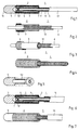
- Figur 1 eine teilweise geschnittene Ansicht der erfindungsgemäßen Elektrode und
- Figur 2 bis 7 die einzelnen Stufen zur Herstellung einer Elektrode gemäß Figur 1.
- Bei dem in Figur 1 dargestellten Ausführungsbeispiel der erfindungsgemäßen Elektrode besteht der elektrisch leitende Bereich 2 der Elektrode aus einer zylinderförmigen Metallhülse 3 und einem um die Metallhülse 3 wendel- oder spiralförmig gewickelten Leiter 4, der bspw. aus demselben Material bestehen kann wie der elektrische Leiter 12 des Elektrodenleiters 1.
- Der Elektrodenleiter 1 besteht aus mehreren dünnen Drahtwendeln 12, vorzugsweise einem vierwendeligen Leiter mit vier nebeneinander gewickelten Drahtwendeln. Die Drahtwendeln 12 schließen einen zentralen Hohlraum oder Lumen 11 ein, in den ein Mandrin zum Plazieren der Elektrode an einer vorbestimmten Stelle eingeführt werden kann.
- Der leitfähige Bereich 2 der Elektrode wird an seinem äußeren Ende von einem Elektrodenkopf 5 abgeschlossen, der eine halbkugelförmige Spitze 51 und eine im Innern der zylinderförmigen Metallhülse 3 plazierte, zylindrische Klemmverbindung 52 aufweist. Die Klemmverbindung zwischen dem Elektrodenleiter 1 und dem Elektrodenkopf 5 wird durch einfaches Zusammenquetschen der Klemmverbindung 52 des Elektrodenkopfes 5 hergestellt.
- Anhand der Figuren 2 bis 7 sollen die einzelnen Schritte zur Herstellung der erfindungsgemäßen Elektrode näher erläutert werden.
- In den Figuren 2 und 3 ist im Schnitt bzw. in Draufsicht der Elektrodenleiter 1 und der leitfähige Bereich 2 der Elektrode dargestellt. Die zylindrische Metallhülse 3 ist in diesem Fertigungsstadium teilweise mit einem vierwendeligen Leiter 4 umwickelt, wobei die Wickelrichtung von der Spitze der Elektrode zur Einführöffnung für den Elektrodenleiter 1 verläuft. Der Elektrodenleiter 1 ist um einen Mitteldraht 6 gewickelt, der wahlweise im Elektrodenleiter 1 verbleiben kann oder nach dem Umwickeln zur Schaffung eines Lumen entfernt wird. Der Elektrodenleiter 1 weist ebenfalls einen vierwendligen Leiter 12 auf.
- Nach dem vollständigen Umwickeln der zylindrischen Metallhülse 3 mit einem vierwendligen Leiter 4 wird die Elektrodenspitze 5 auf den Elektrodenleiter 1 aufgesteckt, der zu diesem Zweck durch die Metallhülse 3 durchgeschoben wird und die Vorderseite des leitfähigen Bereichs 2 um eine bestimmte Länge überragt. die ausreicht, um die Klemmverbindung 52 der Elektrodenspitze 5 aufzunehmen.
- Der in Figur 5 dargestellte Querschnitt durch den Elektrodenkopf 5 zeigt eine halbkugelförmige Spitze 51 und eine hülsenförmig nach hinten fortgesetzte Klemmverbindung 52. Die auf den Elektrodenleiter 1 aufgesteckte Klemmverbindung 52 wird gemäß Figur 6 ringförmig zusammengepreßt und spannt den Elektrodenleiter 1 zwischen sich ein.
- Anschließend wird ein Isolierschlauch 13 aus Silikonkautschuk, Polyurethan oder Polyäthylen vom rückwärtigen Ende des Elektrodenleiters 1 aufgeschoben (Figur 6, Figur 7).
- Die Elektrodenspitze 5 besteht ebenfalls aus Metall, vorzugsweise demselben, körperverträglichen Material wie die wendelförmigen Leiter 4 bzw. die wendelförmigen Leiter 12 des Elektrodenleiters 1.
- Zur Verbesserung der elektrischen Verbindung zwischen dem im Innern der zylindrischen Metallhülse 3 angeordneten Elektrodenleiter 1 und der Metallhülse 3 bzw. dem vierwendligen Leiter 4 am äußeren Umfang der Metallhülse 3 wird eine Schrauben-, Löt- oder Schweißverbindung 7 an der Stirnseite der Metallhülse 3 und der Rückseite des Elektrodenkopfes 5 vorgesehen. Zusätzlich oder alternativ kann eine Verbindung am rückseitigen Ende der Metallhülse 3, bspw. in Form einer Schweiß- oder Lötverbindung hergestellt werden.
- Die Länge der zylindrischen Metallhülse 3 bzw. des leitfähigen Bereichs 2 der Elektrode beträgt ca. 25mm, bei einem Durchmesser von ca. 2 - 3, vorzugsweise 2,2mm.
- Die vorbeschriebene Elektrode kann sowohl als bipolare als auch als monopolare Elektrode verwendet werden, wobei sie in diesem Falle als Anode dient und eine Kathode in an sich bekannter Weise verankert wird.
- Bevorzugt eignet sich die erfindungsgemäße Elektrode für eine Plazierung im Bereich des Brustbeins sowohl in Verbindung mit einer indifferenten Elektrode bei unipolaren Herzschrittmachern als auch in Verbindung mit einer Referenzelektrode bei bipolaren Schrittmachern, wobei die Lage der Referenzelektrode auf eine Position innerhalb des Her zens beschränkt ist, während die indifferente Elektrode bei unipolaren Herzschrittmachern durch das Metallgehäuse des Schrittmachers gebildet wird.
- Die Erfindung beschränkt sich in ihrer Ausführung nicht auf das vorstehend angegebene bevorzugte Ausführungsbeispiel. Vielmehr ist eine Anzahl von Varianten denkbar, welche von der dargestellten Lösung auch bei grundsätzlich anders gearteten Ausführungen Gebrauch machen.
Claims (9)
dadurch gekennzeichnet,
daß der elektrisch leitfähige Bereich (2) der Elektrode zylindrisch ausgebildet ist und einen wendel- oder spiralförmig gestreckten Leiter (4) aufweist.
Applications Claiming Priority (2)
| Application Number | Priority Date | Filing Date | Title |
|---|---|---|---|
| DE8712041U | 1987-09-03 | ||
| DE8712041U DE8712041U1 (de) | 1987-09-03 | 1987-09-03 | Implantierbare Elektrode zur Herzstimulation |
Publications (3)
| Publication Number | Publication Date |
|---|---|
| EP0306442A2 true EP0306442A2 (de) | 1989-03-08 |
| EP0306442A3 EP0306442A3 (en) | 1989-12-13 |
| EP0306442B1 EP0306442B1 (de) | 1994-03-02 |
Family
ID=6811792
Family Applications (1)
| Application Number | Title | Priority Date | Filing Date |
|---|---|---|---|
| EP88730200A Expired - Lifetime EP0306442B1 (de) | 1987-09-03 | 1988-09-05 | Implantierbare Elektrode zur Herzstimulation |
Country Status (2)
| Country | Link |
|---|---|
| EP (1) | EP0306442B1 (de) |
| DE (2) | DE8712041U1 (de) |
Cited By (4)
| Publication number | Priority date | Publication date | Assignee | Title |
|---|---|---|---|---|
| EP0428279A3 (en) * | 1989-11-13 | 1992-08-05 | Telectronics N.V. | Braid electrode leads and catheters and methods for using the same |
| US5876431A (en) * | 1997-07-30 | 1999-03-02 | Sulzer Intermedics Inc. | Small cable endocardial lead with exposed guide tube |
| US8000808B2 (en) * | 2005-01-31 | 2011-08-16 | Medtronic, Inc. | Medical lead with segmented electrode |
| EP2436422A1 (de) | 2010-09-23 | 2012-04-04 | BIOTRONIK SE & Co. KG | Implantierbarer Hydrogelsensor |
Families Citing this family (1)
| Publication number | Priority date | Publication date | Assignee | Title |
|---|---|---|---|---|
| DE102006037122B3 (de) * | 2006-08-09 | 2008-04-03 | Osypka, Peter, Dr.-Ing. | Medizinische Elektrode mit wenigstens zwei Polen und einem Stecker und deren Verwendung |
Family Cites Families (4)
| Publication number | Priority date | Publication date | Assignee | Title |
|---|---|---|---|---|
| US4161952A (en) * | 1977-11-01 | 1979-07-24 | Mieczyslaw Mirowski | Wound wire catheter cardioverting electrode |
| US4481953A (en) * | 1981-11-12 | 1984-11-13 | Cordis Corporation | Endocardial lead having helically wound ribbon electrode |
| US4534366A (en) * | 1983-08-03 | 1985-08-13 | Soukup Thomas M | Carbon fiber pacing electrode |
| US4603705A (en) * | 1984-05-04 | 1986-08-05 | Mieczyslaw Mirowski | Intravascular multiple electrode unitary catheter |
-
1987
- 1987-09-03 DE DE8712041U patent/DE8712041U1/de not_active Expired
-
1988
- 1988-09-05 EP EP88730200A patent/EP0306442B1/de not_active Expired - Lifetime
- 1988-09-05 DE DE88730200T patent/DE3888053D1/de not_active Expired - Fee Related
Cited By (5)
| Publication number | Priority date | Publication date | Assignee | Title |
|---|---|---|---|---|
| EP0428279A3 (en) * | 1989-11-13 | 1992-08-05 | Telectronics N.V. | Braid electrode leads and catheters and methods for using the same |
| US5876431A (en) * | 1997-07-30 | 1999-03-02 | Sulzer Intermedics Inc. | Small cable endocardial lead with exposed guide tube |
| US8000808B2 (en) * | 2005-01-31 | 2011-08-16 | Medtronic, Inc. | Medical lead with segmented electrode |
| EP2436422A1 (de) | 2010-09-23 | 2012-04-04 | BIOTRONIK SE & Co. KG | Implantierbarer Hydrogelsensor |
| US8565895B2 (en) | 2010-09-23 | 2013-10-22 | Biotronik Se & Co. Kg | Implantable electrode lead and hydrogel sensor |
Also Published As
| Publication number | Publication date |
|---|---|
| DE8712041U1 (de) | 1988-10-20 |
| EP0306442A3 (en) | 1989-12-13 |
| DE3888053D1 (de) | 1994-04-07 |
| EP0306442B1 (de) | 1994-03-02 |
Similar Documents
| Publication | Publication Date | Title |
|---|---|---|
| DE69029564T2 (de) | Geflochtene Elektrodenleitungen und Katheter für ihre Benutzung | |
| DE3912377C2 (de) | Spiralförmige Fleckenelektrode für einen Herzdefibrillator bzw. Kardiovertierer | |
| DE69409798T2 (de) | Hochfrequenzleiterbefestigung | |
| DE69514126T2 (de) | Durch Nähen permanent implantierte Elektrode zum Eluieren von Medikamenten | |
| DE2652195C3 (de) | Herzschrittmacherelektrodenanordnung | |
| DE69026081T2 (de) | Subkutane Elektroden zur Entflimmerung | |
| EP0162178B1 (de) | Leitvorrichtung, insbesondere zum mindestens teilweisen Einsetzen in einen menschlichen oder tierischen Körper, mit einer zumindest aus einem Leiter gebildeten Wendel | |
| DE69525125T2 (de) | Medizinischer elektrischer Leiter mit verstärkten Zinken | |
| DE19957241B4 (de) | Elektrische Leitung für medizinische Zwecke und System zur Einführung derselben | |
| EP2711046B1 (de) | Elektrodenleitung und Anschlussstück für elektromedizinische Implantate | |
| US20040162600A1 (en) | Reverse wound electrodes | |
| DE112010001330T5 (de) | MRT-kompatible implantierbare Anschlusselektroden-Schnittstelle | |
| EP0038484A1 (de) | Endocard-Elektrodenanordnung | |
| DE3004852A1 (de) | In den koerper implantierbare vorrichtung zur stimulierung des knochenwachstums | |
| DE2319499A1 (de) | Implantable leitungsanordnung | |
| DE3507119A1 (de) | Regelbare endokardiale elektrodenanordnung | |
| DE69704625T2 (de) | Elektrodenkabel zur elektrischen stimulation | |
| EP3328482B1 (de) | Implantierbare gleichstromelektrodenanordnung | |
| EP1243286A1 (de) | Intravaskuläre Elektrodenleitung | |
| EP0306442B1 (de) | Implantierbare Elektrode zur Herzstimulation | |
| CH656313A5 (en) | Electrode with an electrical conductor which is connected to a contact provided for forming a connection with tissue | |
| DE3043189A1 (de) | Herzschrittmacher-elektrode | |
| EP1285678A2 (de) | Einzel-Elektrodensonde für Herzschrittmachersysteme | |
| EP2478933A2 (de) | Implantierbares Gerät | |
| EP0927561B1 (de) | Defibrillationselektrodenanordnung |
Legal Events
| Date | Code | Title | Description |
|---|---|---|---|
| PUAI | Public reference made under article 153(3) epc to a published international application that has entered the european phase |
Free format text: ORIGINAL CODE: 0009012 |
|
| AK | Designated contracting states |
Kind code of ref document: A2 Designated state(s): DE FR GB |
|
| PUAL | Search report despatched |
Free format text: ORIGINAL CODE: 0009013 |
|
| AK | Designated contracting states |
Kind code of ref document: A3 Designated state(s): DE FR GB |
|
| 17P | Request for examination filed |
Effective date: 19900220 |
|
| 17Q | First examination report despatched |
Effective date: 19921012 |
|
| GRAA | (expected) grant |
Free format text: ORIGINAL CODE: 0009210 |
|
| AK | Designated contracting states |
Kind code of ref document: B1 Designated state(s): DE FR GB |
|
| PG25 | Lapsed in a contracting state [announced via postgrant information from national office to epo] |
Ref country code: GB Effective date: 19940302 Ref country code: FR Free format text: THE PATENT HAS BEEN ANNULLED BY A DECISION OF A NATIONAL AUTHORITY Effective date: 19940302 |
|
| REF | Corresponds to: |
Ref document number: 3888053 Country of ref document: DE Date of ref document: 19940407 |
|
| EN | Fr: translation not filed | ||
| GBV | Gb: ep patent (uk) treated as always having been void in accordance with gb section 77(7)/1977 [no translation filed] |
Effective date: 19940302 |
|
| PLBE | No opposition filed within time limit |
Free format text: ORIGINAL CODE: 0009261 |
|
| STAA | Information on the status of an ep patent application or granted ep patent |
Free format text: STATUS: NO OPPOSITION FILED WITHIN TIME LIMIT |
|
| 26N | No opposition filed | ||
| PGFP | Annual fee paid to national office [announced via postgrant information from national office to epo] |
Ref country code: DE Payment date: 20021102 Year of fee payment: 15 |
|
| PG25 | Lapsed in a contracting state [announced via postgrant information from national office to epo] |
Ref country code: DE Free format text: LAPSE BECAUSE OF NON-PAYMENT OF DUE FEES Effective date: 20040401 |