EP0306337A2 - Spectrophotometer - Google Patents
Spectrophotometer Download PDFInfo
- Publication number
- EP0306337A2 EP0306337A2 EP88308163A EP88308163A EP0306337A2 EP 0306337 A2 EP0306337 A2 EP 0306337A2 EP 88308163 A EP88308163 A EP 88308163A EP 88308163 A EP88308163 A EP 88308163A EP 0306337 A2 EP0306337 A2 EP 0306337A2
- Authority
- EP
- European Patent Office
- Prior art keywords
- light
- light source
- spectrophotometer
- intensity
- emitted
- Prior art date
- Legal status (The legal status is an assumption and is not a legal conclusion. Google has not performed a legal analysis and makes no representation as to the accuracy of the status listed.)
- Granted
Links
- 229910052724 xenon Inorganic materials 0.000 claims abstract description 14
- FHNFHKCVQCLJFQ-UHFFFAOYSA-N xenon atom Chemical compound [Xe] FHNFHKCVQCLJFQ-UHFFFAOYSA-N 0.000 claims abstract description 14
- 230000003287 optical effect Effects 0.000 claims description 2
- 230000003595 spectral effect Effects 0.000 abstract description 25
- WFKWXMTUELFFGS-UHFFFAOYSA-N tungsten Chemical compound [W] WFKWXMTUELFFGS-UHFFFAOYSA-N 0.000 description 4
- 229910052721 tungsten Inorganic materials 0.000 description 4
- 239000010937 tungsten Substances 0.000 description 4
- 238000005286 illumination Methods 0.000 description 3
- 238000000034 method Methods 0.000 description 3
- 238000010276 construction Methods 0.000 description 2
- 238000005259 measurement Methods 0.000 description 2
- 239000000047 product Substances 0.000 description 2
- 238000001228 spectrum Methods 0.000 description 2
- 239000000919 ceramic Substances 0.000 description 1
- 230000000694 effects Effects 0.000 description 1
- 239000012466 permeate Substances 0.000 description 1
Images


Classifications
-
- G—PHYSICS
- G01—MEASURING; TESTING
- G01J—MEASUREMENT OF INTENSITY, VELOCITY, SPECTRAL CONTENT, POLARISATION, PHASE OR PULSE CHARACTERISTICS OF INFRARED, VISIBLE OR ULTRAVIOLET LIGHT; COLORIMETRY; RADIATION PYROMETRY
- G01J3/00—Spectrometry; Spectrophotometry; Monochromators; Measuring colours
- G01J3/02—Details
- G01J3/10—Arrangements of light sources specially adapted for spectrometry or colorimetry
-
- G—PHYSICS
- G01—MEASURING; TESTING
- G01J—MEASUREMENT OF INTENSITY, VELOCITY, SPECTRAL CONTENT, POLARISATION, PHASE OR PULSE CHARACTERISTICS OF INFRARED, VISIBLE OR ULTRAVIOLET LIGHT; COLORIMETRY; RADIATION PYROMETRY
- G01J3/00—Spectrometry; Spectrophotometry; Monochromators; Measuring colours
- G01J3/28—Investigating the spectrum
- G01J3/42—Absorption spectrometry; Double beam spectrometry; Flicker spectrometry; Reflection spectrometry
-
- G—PHYSICS
- G01—MEASURING; TESTING
- G01J—MEASUREMENT OF INTENSITY, VELOCITY, SPECTRAL CONTENT, POLARISATION, PHASE OR PULSE CHARACTERISTICS OF INFRARED, VISIBLE OR ULTRAVIOLET LIGHT; COLORIMETRY; RADIATION PYROMETRY
- G01J3/00—Spectrometry; Spectrophotometry; Monochromators; Measuring colours
- G01J3/02—Details
-
- G—PHYSICS
- G01—MEASURING; TESTING
- G01N—INVESTIGATING OR ANALYSING MATERIALS BY DETERMINING THEIR CHEMICAL OR PHYSICAL PROPERTIES
- G01N21/00—Investigating or analysing materials by the use of optical means, i.e. using sub-millimetre waves, infrared, visible or ultraviolet light
- G01N21/17—Systems in which incident light is modified in accordance with the properties of the material investigated
- G01N21/47—Scattering, i.e. diffuse reflection
- G01N21/4738—Diffuse reflection, e.g. also for testing fluids, fibrous materials
- G01N21/474—Details of optical heads therefor, e.g. using optical fibres
-
- G—PHYSICS
- G01—MEASURING; TESTING
- G01J—MEASUREMENT OF INTENSITY, VELOCITY, SPECTRAL CONTENT, POLARISATION, PHASE OR PULSE CHARACTERISTICS OF INFRARED, VISIBLE OR ULTRAVIOLET LIGHT; COLORIMETRY; RADIATION PYROMETRY
- G01J1/00—Photometry, e.g. photographic exposure meter
- G01J1/10—Photometry, e.g. photographic exposure meter by comparison with reference light or electric value provisionally void
- G01J1/20—Photometry, e.g. photographic exposure meter by comparison with reference light or electric value provisionally void intensity of the measured or reference value being varied to equalise their effects at the detectors, e.g. by varying incidence angle
- G01J1/34—Photometry, e.g. photographic exposure meter by comparison with reference light or electric value provisionally void intensity of the measured or reference value being varied to equalise their effects at the detectors, e.g. by varying incidence angle using separate light paths used alternately or sequentially, e.g. flicker
- G01J1/36—Photometry, e.g. photographic exposure meter by comparison with reference light or electric value provisionally void intensity of the measured or reference value being varied to equalise their effects at the detectors, e.g. by varying incidence angle using separate light paths used alternately or sequentially, e.g. flicker using electric radiation detectors
-
- G—PHYSICS
- G01—MEASURING; TESTING
- G01J—MEASUREMENT OF INTENSITY, VELOCITY, SPECTRAL CONTENT, POLARISATION, PHASE OR PULSE CHARACTERISTICS OF INFRARED, VISIBLE OR ULTRAVIOLET LIGHT; COLORIMETRY; RADIATION PYROMETRY
- G01J1/00—Photometry, e.g. photographic exposure meter
- G01J1/10—Photometry, e.g. photographic exposure meter by comparison with reference light or electric value provisionally void
- G01J1/16—Photometry, e.g. photographic exposure meter by comparison with reference light or electric value provisionally void using electric radiation detectors
- G01J1/1626—Arrangements with two photodetectors, the signals of which are compared
- G01J2001/1636—Arrangements with two photodetectors, the signals of which are compared one detector directly monitoring the source, e.g. also impulse time controlling
- G01J2001/1642—Arrangements with two photodetectors, the signals of which are compared one detector directly monitoring the source, e.g. also impulse time controlling and acting on the detecting circuit
-
- G—PHYSICS
- G01—MEASURING; TESTING
- G01J—MEASUREMENT OF INTENSITY, VELOCITY, SPECTRAL CONTENT, POLARISATION, PHASE OR PULSE CHARACTERISTICS OF INFRARED, VISIBLE OR ULTRAVIOLET LIGHT; COLORIMETRY; RADIATION PYROMETRY
- G01J3/00—Spectrometry; Spectrophotometry; Monochromators; Measuring colours
- G01J3/28—Investigating the spectrum
- G01J3/42—Absorption spectrometry; Double beam spectrometry; Flicker spectrometry; Reflection spectrometry
- G01J2003/425—Reflectance
-
- G—PHYSICS
- G01—MEASURING; TESTING
- G01N—INVESTIGATING OR ANALYSING MATERIALS BY DETERMINING THEIR CHEMICAL OR PHYSICAL PROPERTIES
- G01N2201/00—Features of devices classified in G01N21/00
- G01N2201/06—Illumination; Optics
- G01N2201/065—Integrating spheres
-
- G—PHYSICS
- G01—MEASURING; TESTING
- G01N—INVESTIGATING OR ANALYSING MATERIALS BY DETERMINING THEIR CHEMICAL OR PHYSICAL PROPERTIES
- G01N2201/00—Features of devices classified in G01N21/00
- G01N2201/06—Illumination; Optics
- G01N2201/069—Supply of sources
- G01N2201/0696—Pulsed
Definitions
- the present invention relates to a spectrophotometer, and more particularly, to a spectrophotometer using a pulsed xenon flashtube.
- a spectrophotometer is used to make measurements of the spectral reflectance of an object within a predetermined period of time and utilized to perform a color matching. While the optical configuration of the spectrophotometer is capable of taking many forms, the light source thereof irradiates a sample and the light reflected from the sample is introduced into a spectroscope so that a spectrum can be obtained.
- the spectrophotometer uses various light sources therein, it normally uses a tungsten lamp.
- the tungsten lamp In order for the tungsten lamp to provide a reliable spectrum reflectance, it is necessary that the signal-to-noise ratio ((S/N) ratio) thereof is high caused by the emission of an intense light from the light source thereof.
- the tungsten lamp has a disadvantage that its heat amount becomes great when its light emission intensity is high.
- US Patent No. 4,076,421 or its corresponding Japanese Patent Publication No. 52183/1978 discloses a spectrophotometer using a pulsed xenon flashtube as the light source thereof.
- the xenon flashtube provides a small heat amount and a high S/N ratio compared with those provided by a tungsten tube.
- the reason the pulsed xenon flashtube is used as the light source is because the spectral content thereof is extremely stable and enables the compensation for flash-to-flash variations using single broadband-response photodetector. That is, the high intensity and short pulse width renders an electronic circuit which is high-pass filtered extremely insensitive to the effects of ambient lights.
- the known spectrophotometer is intended to allow the light source thereof to emit an intense light. It is to be noted herein that 15 joules of energy is applied to spectrophotometers according to the US Patent No. 4,076,421 and that the xenon flashtube provides a short, intense pulse of illumination of approximately tens of microseconds duration.
- the period of time required for charging the spectrophotometer namely, flash-to-flash period takes as long as one second in order to provide a short, intense pulse of illumination of tens of microseconds by inputting 15 joules of energy to the spectrophotometer. Accordingly, the spectrophotometer flashes only approximately four to ten times within a predetermined period of time during a spectral reflectance-measuring operation.
- the present invention has been made with a view to solving the above-described problems and has for its essential object to provide a spectrophotometer which is capable of measuring the spectral reflectance of an object using a pulsed xenon flashtube under a natural light (or equivalents) and emits lights many times within a predetermined measuring time, thus providing highly, accurate data.
- the energy to be applied to the spectrophotometer comprising a pulsed xenon flashtube is set to be 0.03 joules or more and 1.0 joule or less.
- the spectrophotometer in accordance with the present invention the spectral content of a light emitted from the pulsed xenon flashtube is very reliable and the S/N ratio thereof is high, and further, the use of a single broadband-response photodetector enables the compensation for emission-to-emission intensity variations of the light source of the spectrophotometer.
- the energy applied to the spectrophotometer is set to be 0.03 joules or more and 1.0 joule or less, a spectral reflectance of the object can be measured under a natural light (or equivalents).
- the period of time required for the light source to be charged is short before the light source emits a light having a desired intensity is obtained. Accordingly, the light source emits lights as many as 10 to 36 times per second.
- the spectrophotometer provides more data within a predetermined period of time, which leads to the supply of accurate data.
- the intensity of the light emitted from the light source becomes weak, and the S/N ratio thereof becomes low. In this case, the accuracy of measurements of the spectral reflectance is inaccurate.
- the energy to be applied thereto is above 1.0 joule, the intensity of the light emitted from the light source becomes too intense, so that the condition in which the spectral reflectance is measured differs greatly from the condition in which a natural light or equivalents are present.
- the spectral reflectance of a sample can be measured using the pulsed xenon flashtube under a condition in which a natural light or equivalents are present. Further, the light source emits lights many times within a predetermined measuring period, thereby providing accurate data.
- Fig. 1 is a diagrammatic view showing a schematic construction of a spectrophotometer according to one preferred embodiment of the present invention.
- a pulsed xenon flashtube is used as a light source 1.
- the energy to be applied to the spectrophotometer can be set from 0.03 or more and 1.0 joule or less.
- a sample 2 is placed at an lower aperture of an integrating sphere 3.
- a rotary chopper 4 is disposed above the integrating sphere 3.
- the rotation of the rotary chopper 4 rotating at a constant speed allows the alternate introductions of a light reflected from a sample (hereinafter referred to as sample light) and a light reflected from the inner circumferential face of the integrating sphere 3 (hereinafter referred to as reference light) into a spectroscope 8 with photodetectors.
- sample light a light reflected from a sample
- reference light a light reflected from the inner circumferential face of the integrating sphere 3
- a switching means having the same function of the rotary chopper 4, namely, the function of alternately introducing the sample light and the reference light into the spectroscope 8 may be provided instead of the rotary chopper 4.
- a photosensor is provided on the outer periphery of the rotary chopper 4 as a synchronizing sensor 5.
- the synchronizing sensor 5 allows the light source 1 to emit a light according to the rotation speed of the rotary chopper 4.
- the synchronizing sensor 5 detects that the rotary chopper 4 is at the position at which the rotary chopper 4 introduces the sample light or the reference light into the spectroscope 8, thus outputting to the light source 1 a trigger signal for causing the light emission from the light source 1.
- the synchronizing sensor 5 outputs to a reflectance factor arithmetic circuit 13 a distinguishing signal for distinguishing the kind of data transmitted from the integrating sphere 3 thereto.
- the spectrophotometer further comprises a mirror 6 for reflecting the reference light and introducing it into the spectroscope 8 and a half mirror 7 for introducing the sample light into the spectroscope 8.
- a light source intensity-sensor 10 is placed in a window of the integrating sphere 3 with a certain distance provided from the position at which the sample 2 is placed.
- the light source-intensity sensor 10 detects the intensity of a light every time the light source 1 emits a light.
- the fluctuation of the intensity of the light emitted from the light source 1 can be compensated by finding the ratio of data values (the intensities of the sample light and the reference light) to the intensity of the light reflected from the light source 1.
- the fluctuation of the intensity of the light source 1 can be compensated by finding the ratio of the intensity of the sample light to the intensity of the light emitted from the light source 1 and the ratio of the intensity of the reference light to the intensity of the light emitted from the light source 1.
- Separated spectroscopes 8 may be provided in positions at which they are, respectively, capable of receiving the sample light and the reference light so that signals are transmitted therefrom to an amplifier 9.
- the means 4 having the function of introducing the sample light and the reference light into the spectroscope 8 and the synchronizing sensor 5 can be omitted from the spectrophotometer.
- the signal of spectral data outputted from the spectroscope 8 and the signal of the intensity of the light emitted from the light source 1 obtained by the light source intensity-sensor 10 are inputted to a compensation circuit 12, and thereafter, to the reflectance factor arithmetic circuit 13 through the amplifier 9 and an analog-to-digital converter 11.
- the compensation circuit 12 calculates the ratio (A) of the the intensity of the sample light to the intensity of the light emitted from the light source 1 and the ratio (B) of the intensity of the reference light to the intensity of the light emitted from the light source 1.
- the reflectance factor arithmetic circuit 13 calculates the ratio (A) to the ratio (B).
- the reflectance factor arithmetic circuit 13 outputs the ratio A/B as the spectral reflectance of the sample 2.
- the circuits 12 and 13 can be replaced by a microcomputer which perform the same functions as that of the circuits 12 and 13.
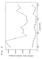
- Fig. 2 is a graph showing the result obtained from tests conducted by a spectrophotometer according to the present invention to examine the reproducibilities of the spectral reflectances of respective wavelengths.
- Fig. 3 is a graph showing the result obtained from tests conducted by a known spectrophotometer oh the same sample and in the same condition.
- the axes of ordinates shown in Figs. 2 and 3 indicate reflection factor standard deviations, and the axes of abscissa shown in Figs. 2 and 3 indicate wavelengths.
- ceramic white plates are used as samples having high reflection factors and black velvets are used as samples having low reflection factors.
- the polygonal lines formed by plotting measuring points by " ⁇ " show data having the high reflection factors, and those formed by plotting measuring points by " ⁇ " show data having the low reflection factors.
- 0.15 joules of energy is applied to the light source 1.
- the known spectrophotometer emits a light once a second whereas the spectrophotometer according to the present invention emits lights 16 times per second.
- the graphs show, according to the tests using the conventional spectrophotometer, the spectral reflectance of the sample having the high spectral reflectance greatly fluctuates whereas according to the embodiment of the present invention, the fluctuation of the spectral reflectance of the sample having the high spectral reflectance is very small. Even the fluctuation of the spectral reflectance of the sample having the low spectral reflectance obtained using the spectrophotometer according to the present invention is equal to or smaller than that of the spectral reflectance obtained using the known spectrophotometer.
- the fluctuation of the intensity emitted from the light source 1 is compensated by the ratio of the data values (light emission intensities of the sample light and the reference light) to the intensity of the light emitted from the light source 1 every time the light source 1 emits a light, however, the compensation can be made as well by finding the ratio of the product of the emission light intensities of the sample lights to the addition of the intensities of the light emitted from the light source 1, and the ratio of the product of the light emission intensities of the reference lights to the addition of the light intensities of the lights emitted from the light source 1. According to this method, the period of time required for performing an arithmetic is shortened for the compensation of the fluctuation of the light source 1, and further, the accuracy of the spectral reflectance obtained by this method is almost equal to that of the embodiment described above.
- the spectrophotometer it is preferable for further improving the measuring accuracy of the spectrophotometer according to the present invention to provide the spectrophotometer with means for detecting the fluctuation of the intensity of the light emitted from the light source 1 according to a signal inputted thereto and performing a feedback control in response to the signal so that the energy to be applied to the spectrophotometer is controlled, thus reducing the fluctuation of the intensity of the light emitted from the light source 1.
Landscapes
- Physics & Mathematics (AREA)
- Spectroscopy & Molecular Physics (AREA)
- General Physics & Mathematics (AREA)
- Health & Medical Sciences (AREA)
- Life Sciences & Earth Sciences (AREA)
- Chemical & Material Sciences (AREA)
- Analytical Chemistry (AREA)
- Biochemistry (AREA)
- General Health & Medical Sciences (AREA)
- Immunology (AREA)
- Pathology (AREA)
- Spectrometry And Color Measurement (AREA)
- Investigating Or Analysing Materials By Optical Means (AREA)
Abstract
Description
- The present invention relates to a spectrophotometer, and more particularly, to a spectrophotometer using a pulsed xenon flashtube.
- A spectrophotometer is used to make measurements of the spectral reflectance of an object within a predetermined period of time and utilized to perform a color matching. While the optical configuration of the spectrophotometer is capable of taking many forms, the light source thereof irradiates a sample and the light reflected from the sample is introduced into a spectroscope so that a spectrum can be obtained.
- While the spectrophotometer uses various light sources therein, it normally uses a tungsten lamp. In order for the tungsten lamp to provide a reliable spectrum reflectance, it is necessary that the signal-to-noise ratio ((S/N) ratio) thereof is high caused by the emission of an intense light from the light source thereof. However, the tungsten lamp has a disadvantage that its heat amount becomes great when its light emission intensity is high.
- US Patent No. 4,076,421 or its corresponding Japanese Patent Publication No. 52183/1978 discloses a spectrophotometer using a pulsed xenon flashtube as the light source thereof. The xenon flashtube provides a small heat amount and a high S/N ratio compared with those provided by a tungsten tube. The reason the pulsed xenon flashtube is used as the light source is because the spectral content thereof is extremely stable and enables the compensation for flash-to-flash variations using single broadband-response photodetector. That is, the high intensity and short pulse width renders an electronic circuit which is high-pass filtered extremely insensitive to the effects of ambient lights. Thus, the known spectrophotometer is intended to allow the light source thereof to emit an intense light. It is to be noted herein that 15 joules of energy is applied to spectrophotometers according to the US Patent No. 4,076,421 and that the xenon flashtube provides a short, intense pulse of illumination of approximately tens of microseconds duration.
- However, when a spectral reflectance is determined using a light source which provides such an intense pulse of illumination by applying a great amount of energy to a spectrophotometer, the following occurs: Lights may permeate deep into the sample to a great extent depending on a surface structure of the sample. Thus, even undesired information of the sample may be obtained: Data obtained using such a spectrophotometer has no correlation to the data obtained under a natural light (or equivalents): The intensity of a light emitted from the light source of the spectrophotometer fluctuates in a great extent. Therefore, when the intensity of the sample having a high reflection factor is detected, it is difficult to compensate the fluctuation of the intensity of the light reflected therefrom even if intensity of the light is detected. Thus, an accurate data of a spectral reflectance cannot be obtained.
- In addition, the period of time required for charging the spectrophotometer, namely, flash-to-flash period takes as long as one second in order to provide a short, intense pulse of illumination of tens of microseconds by inputting 15 joules of energy to the spectrophotometer. Accordingly, the spectrophotometer flashes only approximately four to ten times within a predetermined period of time during a spectral reflectance-measuring operation.
- The present invention has been made with a view to solving the above-described problems and has for its essential object to provide a spectrophotometer which is capable of measuring the spectral reflectance of an object using a pulsed xenon flashtube under a natural light (or equivalents) and emits lights many times within a predetermined measuring time, thus providing highly, accurate data.
- In accomplishing this and other objects, a spectrophotometer according to one preferred embodiment of the present invention, the energy to be applied to the spectrophotometer comprising a pulsed xenon flashtube is set to be 0.03 joules or more and 1.0 joule or less.
- According to the spectrophotometer in accordance with the present invention, the spectral content of a light emitted from the pulsed xenon flashtube is very reliable and the S/N ratio thereof is high, and further, the use of a single broadband-response photodetector enables the compensation for emission-to-emission intensity variations of the light source of the spectrophotometer. In addition, since the energy applied to the spectrophotometer is set to be 0.03 joules or more and 1.0 joule or less, a spectral reflectance of the object can be measured under a natural light (or equivalents). Furthermore, the period of time required for the light source to be charged is short before the light source emits a light having a desired intensity is obtained. Accordingly, the light source emits lights as many as 10 to 36 times per second. In other words, the spectrophotometer provides more data within a predetermined period of time, which leads to the supply of accurate data.
- When the energy to be applied to the spectrophotometer is below 0.03 joules, the intensity of the light emitted from the light source becomes weak, and the S/N ratio thereof becomes low. In this case, the accuracy of measurements of the spectral reflectance is inaccurate. On the other hand, when the energy to be applied thereto is above 1.0 joule, the intensity of the light emitted from the light source becomes too intense, so that the condition in which the spectral reflectance is measured differs greatly from the condition in which a natural light or equivalents are present.
- As apparent from the foregoing description, the following advantages can be obtained according to the present invention.
- The spectral reflectance of a sample can be measured using the pulsed xenon flashtube under a condition in which a natural light or equivalents are present. Further, the light source emits lights many times within a predetermined measuring period, thereby providing accurate data.
- These and other objects and feature of the present invention will become apparent from the following description taken in conjunction with the preferred embodiment thereof with reference to the accompanying drawings, in which:
- Fig. 1 is a diagrammatic view showing a schematic construction of a spectrophotometer according to one embodiment of the present invention;
- Fig. 2 is a graph showing the result obtained in a test conducted to measure the reproducibility of the spectral reflectance of respective wavelengths according to an embodiment of a spectrophotometer of the present invention; and
- Fig. 3 is a graph showing the result obtained in a test conducted to measure the reproducibility of the spectral reflectance of respective wavelengths on the same sample and in a similar condition according to a known spectrophotometer.
- One preferred embodiment of the present invention is described hereinbelow with reference to Figs. 1 through 3.
- Fig. 1 is a diagrammatic view showing a schematic construction of a spectrophotometer according to one preferred embodiment of the present invention. A pulsed xenon flashtube is used as a
light source 1. The energy to be applied to the spectrophotometer can be set from 0.03 or more and 1.0 joule or less. Asample 2 is placed at an lower aperture of anintegrating sphere 3. A rotary chopper 4 is disposed above the integratingsphere 3. The rotation of the rotary chopper 4 rotating at a constant speed allows the alternate introductions of a light reflected from a sample (hereinafter referred to as sample light) and a light reflected from the inner circumferential face of the integrating sphere 3 (hereinafter referred to as reference light) into aspectroscope 8 with photodetectors. A switching means having the same function of the rotary chopper 4, namely, the function of alternately introducing the sample light and the reference light into thespectroscope 8 may be provided instead of the rotary chopper 4. A photosensor is provided on the outer periphery of the rotary chopper 4 as a synchronizing sensor 5. The synchronizing sensor 5 allows thelight source 1 to emit a light according to the rotation speed of the rotary chopper 4. The synchronizing sensor 5 detects that the rotary chopper 4 is at the position at which the rotary chopper 4 introduces the sample light or the reference light into thespectroscope 8, thus outputting to the light source 1 a trigger signal for causing the light emission from thelight source 1. In addition, the synchronizing sensor 5 outputs to a reflectance factor arithmetic circuit 13 a distinguishing signal for distinguishing the kind of data transmitted from theintegrating sphere 3 thereto. The spectrophotometer further comprises amirror 6 for reflecting the reference light and introducing it into thespectroscope 8 and ahalf mirror 7 for introducing the sample light into thespectroscope 8. A light source intensity-sensor 10 is placed in a window of the integratingsphere 3 with a certain distance provided from the position at which thesample 2 is placed. The light source-intensity sensor 10 detects the intensity of a light every time thelight source 1 emits a light. The fluctuation of the intensity of the light emitted from thelight source 1 can be compensated by finding the ratio of data values (the intensities of the sample light and the reference light) to the intensity of the light reflected from thelight source 1. That is, the fluctuation of the intensity of thelight source 1 can be compensated by finding the ratio of the intensity of the sample light to the intensity of the light emitted from thelight source 1 and the ratio of the intensity of the reference light to the intensity of the light emitted from thelight source 1. -
Separated spectroscopes 8 may be provided in positions at which they are, respectively, capable of receiving the sample light and the reference light so that signals are transmitted therefrom to an amplifier 9. Thus, the means 4 having the function of introducing the sample light and the reference light into thespectroscope 8 and the synchronizing sensor 5 can be omitted from the spectrophotometer. - The signal of spectral data outputted from the
spectroscope 8 and the signal of the intensity of the light emitted from thelight source 1 obtained by the light source intensity-sensor 10 are inputted to acompensation circuit 12, and thereafter, to the reflectance factorarithmetic circuit 13 through the amplifier 9 and an analog-to-digital converter 11. Thecompensation circuit 12 calculates the ratio (A) of the the intensity of the sample light to the intensity of the light emitted from thelight source 1 and the ratio (B) of the intensity of the reference light to the intensity of the light emitted from thelight source 1. The reflectance factorarithmetic circuit 13 calculates the ratio (A) to the ratio (B). The reflectance factorarithmetic circuit 13 outputs the ratio A/B as the spectral reflectance of thesample 2. In addition, thecircuits circuits - Fig. 2 is a graph showing the result obtained from tests conducted by a spectrophotometer according to the present invention to examine the reproducibilities of the spectral reflectances of respective wavelengths. Fig. 3 is a graph showing the result obtained from tests conducted by a known spectrophotometer oh the same sample and in the same condition. The axes of ordinates shown in Figs. 2 and 3 indicate reflection factor standard deviations, and the axes of abscissa shown in Figs. 2 and 3 indicate wavelengths. In the tests, ceramic white plates are used as samples having high reflection factors and black velvets are used as samples having low reflection factors. The polygonal lines formed by plotting measuring points by " ○ " show data having the high reflection factors, and those formed by plotting measuring points by " ● " show data having the low reflection factors. In the tests using the spectrophotometer according to the present invention, 0.15 joules of energy is applied to the
light source 1. The known spectrophotometer emits a light once a second whereas the spectrophotometer according to the present invention emits lights 16 times per second. As the graphs show, according to the tests using the conventional spectrophotometer, the spectral reflectance of the sample having the high spectral reflectance greatly fluctuates whereas according to the embodiment of the present invention, the fluctuation of the spectral reflectance of the sample having the high spectral reflectance is very small. Even the fluctuation of the spectral reflectance of the sample having the low spectral reflectance obtained using the spectrophotometer according to the present invention is equal to or smaller than that of the spectral reflectance obtained using the known spectrophotometer. - In this embodiment, the fluctuation of the intensity emitted from the
light source 1 is compensated by the ratio of the data values (light emission intensities of the sample light and the reference light) to the intensity of the light emitted from thelight source 1 every time thelight source 1 emits a light, however, the compensation can be made as well by finding the ratio of the product of the emission light intensities of the sample lights to the addition of the intensities of the light emitted from thelight source 1, and the ratio of the product of the light emission intensities of the reference lights to the addition of the light intensities of the lights emitted from thelight source 1. According to this method, the period of time required for performing an arithmetic is shortened for the compensation of the fluctuation of thelight source 1, and further, the accuracy of the spectral reflectance obtained by this method is almost equal to that of the embodiment described above. - In addition to the above-described method, it is preferable for further improving the measuring accuracy of the spectrophotometer according to the present invention to provide the spectrophotometer with means for detecting the fluctuation of the intensity of the light emitted from the
light source 1 according to a signal inputted thereto and performing a feedback control in response to the signal so that the energy to be applied to the spectrophotometer is controlled, thus reducing the fluctuation of the intensity of the light emitted from thelight source 1.
Claims (6)
said light source (1) comprising a pulsed xenon flashtube;
an integrating sphere (3) in which light from said light source (1) is emitted;
a spectroscope (8) for detecting an intensity of respective wavelengths of a light reflected from an inner circumferential face of said integrating sphere (3) and an intensity of respective wavelengths of a light reflected from a sample (2) disposed on said integrating sphere (3); and
a sensor (10) for detecting intensity of the light emitted from said light source (1).
said light source (1) comprising a pulsed xenon flashtube;
an integrating sphere (3) in which a light from said light source (1) is emitted;
a switching means (4) for alternately selecting a light reflected from the inner circumferential face of said integrating sphere (3) and light reflected from the sample (2) disposed on said integrating sphere (3);
optical system (6 and 7) for introducing, said selected light into said spectroscope (8);
a synchronizing sensor (5) for detecting switching timing of said switching means (4); and
a sensor (10) for detecting the intensity of the light emitted from said light source (1).
a compensation means (12) for calculating a ratio of an intensity of the light reflected from the inner circumferential face of said integrating sphere (3) to an intensity of the light emitted from the light source (1) and a ratio of an intensity of the light reflected from said sample (2) to an intensity of the light emitted from said light source (1) every time said light source (1) emits a light and finding said respective ratios, whereby the fluctuation of the intensity of the light emitted from said light source (1) is compensated.
a compensation means (12) for calculating a product of the intensities of lights reflected from the inner circumferential face of said integrating sphere (3) to a product of the intensities of lights emitted from said light source (1} and the ratio of the product of the intensities of lights reflected from said sample (2) to the product of the intensities of lights emitted from said light source (1) every time said light source (1) emits a plurality of lights, whereby the fluctuation of the intensity of the light emitted from said light source (1) is compensated.
Applications Claiming Priority (2)
| Application Number | Priority Date | Filing Date | Title |
|---|---|---|---|
| JP62222454A JP2604754B2 (en) | 1987-09-04 | 1987-09-04 | Spectrophotometer |
| JP222454/87 | 1987-09-04 |
Publications (3)
| Publication Number | Publication Date |
|---|---|
| EP0306337A2 true EP0306337A2 (en) | 1989-03-08 |
| EP0306337A3 EP0306337A3 (en) | 1990-09-19 |
| EP0306337B1 EP0306337B1 (en) | 1993-12-15 |
Family
ID=16782665
Family Applications (1)
| Application Number | Title | Priority Date | Filing Date |
|---|---|---|---|
| EP88308163A Expired - Lifetime EP0306337B1 (en) | 1987-09-04 | 1988-09-02 | Spectrophotometer |
Country Status (5)
| Country | Link |
|---|---|
| US (1) | US4921351A (en) |
| EP (1) | EP0306337B1 (en) |
| JP (1) | JP2604754B2 (en) |
| KR (1) | KR970005587B1 (en) |
| DE (1) | DE3886308T2 (en) |
Cited By (4)
| Publication number | Priority date | Publication date | Assignee | Title |
|---|---|---|---|---|
| EP0569104A1 (en) * | 1992-05-08 | 1993-11-10 | X-Rite, Inc. | Portable spectrophotometer |
| WO1998012541A1 (en) * | 1996-09-16 | 1998-03-26 | Varian Australia Pty. Ltd. | Improved spectrophotometer |
| AU730982B2 (en) * | 1996-09-16 | 2001-03-22 | Agilent Technologies Australia (M) Pty Ltd | Improved spectrophotometer |
| WO2012020440A1 (en) * | 2010-08-12 | 2012-02-16 | Consiglio Nazionale Delle Ricerche | Device for diffuse light spectroscopy |
Families Citing this family (12)
| Publication number | Priority date | Publication date | Assignee | Title |
|---|---|---|---|---|
| US5422726A (en) * | 1993-02-16 | 1995-06-06 | Tyler; Jonathan M. | Solid state spectrofluorimeter and method of using the same |
| US5381010A (en) * | 1993-12-03 | 1995-01-10 | Sleepair Corporation | Periodically alternating path and alternating wavelength bridges for quantitative and ultrasensitive measurement of vapor concentration |
| US6424413B1 (en) * | 1998-06-12 | 2002-07-23 | Gretagmacbeth Llc | Multi-channel integrating sphere |
| US6444971B1 (en) * | 1999-12-31 | 2002-09-03 | Leica Microsystems Heidelberg Gmbh | Method and system for compensating intensity fluctuations of an illumination system in a confocal microscope |
| JP4852762B2 (en) * | 2007-03-13 | 2012-01-11 | 国立大学法人島根大学 | Fiber optic lighting equipment |
| JP5296723B2 (en) * | 2010-02-18 | 2013-09-25 | 株式会社日立ハイテクノロジーズ | Spectrophotometer and performance measurement method thereof |
| ES2366290B1 (en) | 2010-10-20 | 2012-08-27 | Abengoa Solar New Technologies S.A. | SPECTROPHOTOMETER FOR AUTOMATIC OPTICAL CHARACTERIZATION OF SOLAR COLLECTOR TUBES AND OPERATING METHOD. |
| US8711335B2 (en) * | 2011-06-28 | 2014-04-29 | Nikon Corporation | Stroboscopic light source for a transmitter of a large scale metrology system |
| US8848202B2 (en) * | 2011-11-11 | 2014-09-30 | Intersil Americas LLC | Optical proximity sensors with offset compensation |
| US8994926B2 (en) | 2012-02-14 | 2015-03-31 | Intersil Americas LLC | Optical proximity sensors using echo cancellation techniques to detect one or more objects |
| US8599374B1 (en) * | 2012-11-15 | 2013-12-03 | Corning Incorporated | Hyperspectral imaging systems and methods for imaging a remote object |
| US10371628B2 (en) * | 2017-08-07 | 2019-08-06 | The Boeing Company | Apparatus for measuring spectral hemispherical reflectance of samples at grazing angles |
Citations (6)
| Publication number | Priority date | Publication date | Assignee | Title |
|---|---|---|---|---|
| US3446972A (en) * | 1966-07-18 | 1969-05-27 | Kollmorgen Corp | Automatic gain control for photomultiplier tubes employing a monitoring photocell |
| US3810696A (en) * | 1973-02-20 | 1974-05-14 | Waters Associates Inc | Improved analytical apparatus for measuring light absorbance of fluids |
| FR2319895A1 (en) * | 1975-07-30 | 1977-02-25 | Unilever Nv | MEASURING INSTRUMENTS IN PARTICULAR FOR MEASURING OPTICAL REFLECTANCE |
| US4076421A (en) * | 1976-03-23 | 1978-02-28 | Kollmorgen Technologies Corporation | Spectrophotometer with parallel sensing |
| JPS56122936A (en) * | 1980-02-29 | 1981-09-26 | Shimadzu Corp | Reflection factor measuring device |
| DE3332986A1 (en) * | 1983-09-10 | 1985-04-04 | Optronik Gmbh, 1000 Berlin | Reflectivity meter for measuring the spectral radiance factor for 45/0 measuring geometry |
Family Cites Families (3)
| Publication number | Priority date | Publication date | Assignee | Title |
|---|---|---|---|---|
| US3458261A (en) * | 1964-09-25 | 1969-07-29 | Kollmorgen Corp | Pulsed light photometric apparatus for measuring light characteristics of moving materials |
| EP0047094B1 (en) * | 1980-08-21 | 1986-11-20 | Oriel Scientific Limited | Analytical optical instruments |
| DE3686184T2 (en) * | 1985-03-21 | 1993-02-25 | Abbott Lab | SPECTRAL PHOTOMETER. |
-
1987
- 1987-09-04 JP JP62222454A patent/JP2604754B2/en not_active Expired - Fee Related
-
1988
- 1988-09-02 DE DE88308163T patent/DE3886308T2/en not_active Expired - Fee Related
- 1988-09-02 EP EP88308163A patent/EP0306337B1/en not_active Expired - Lifetime
- 1988-09-03 KR KR1019880011373A patent/KR970005587B1/en not_active IP Right Cessation
- 1988-09-06 US US07/240,617 patent/US4921351A/en not_active Expired - Lifetime
Patent Citations (6)
| Publication number | Priority date | Publication date | Assignee | Title |
|---|---|---|---|---|
| US3446972A (en) * | 1966-07-18 | 1969-05-27 | Kollmorgen Corp | Automatic gain control for photomultiplier tubes employing a monitoring photocell |
| US3810696A (en) * | 1973-02-20 | 1974-05-14 | Waters Associates Inc | Improved analytical apparatus for measuring light absorbance of fluids |
| FR2319895A1 (en) * | 1975-07-30 | 1977-02-25 | Unilever Nv | MEASURING INSTRUMENTS IN PARTICULAR FOR MEASURING OPTICAL REFLECTANCE |
| US4076421A (en) * | 1976-03-23 | 1978-02-28 | Kollmorgen Technologies Corporation | Spectrophotometer with parallel sensing |
| JPS56122936A (en) * | 1980-02-29 | 1981-09-26 | Shimadzu Corp | Reflection factor measuring device |
| DE3332986A1 (en) * | 1983-09-10 | 1985-04-04 | Optronik Gmbh, 1000 Berlin | Reflectivity meter for measuring the spectral radiance factor for 45/0 measuring geometry |
Non-Patent Citations (3)
| Title |
|---|
| JOURNAL OF APPLIED PHOTOGRAPHIC ENGINEERING, vol. 3, no. 1, Winter 1977, pages 4-6, Soc. of Photographic Scientists and Engineers; S.J. KISHNER: "Pulsed-xenon densitometry". * |
| PATENT ABSTRACTS OF JAPAN, vol. 5, no. 201 (P-94)(873) 19 December 1981 & JP-A-56 122 936 (SHIMAZU SEISAKUSHO K.K.) 26-09-1981 * |
| Patent Abstracts of Japan, vol. 5, no. 201 (P-94)(873), 19.12.81 & JP-A-56 122 936 * |
Cited By (6)
| Publication number | Priority date | Publication date | Assignee | Title |
|---|---|---|---|---|
| EP0569104A1 (en) * | 1992-05-08 | 1993-11-10 | X-Rite, Inc. | Portable spectrophotometer |
| US5369481A (en) * | 1992-05-08 | 1994-11-29 | X-Rite, Incorporated | Portable spectrophotometer |
| WO1998012541A1 (en) * | 1996-09-16 | 1998-03-26 | Varian Australia Pty. Ltd. | Improved spectrophotometer |
| US6002477A (en) * | 1996-09-16 | 1999-12-14 | Varian, Inc. | Spectrophotometer |
| AU730982B2 (en) * | 1996-09-16 | 2001-03-22 | Agilent Technologies Australia (M) Pty Ltd | Improved spectrophotometer |
| WO2012020440A1 (en) * | 2010-08-12 | 2012-02-16 | Consiglio Nazionale Delle Ricerche | Device for diffuse light spectroscopy |
Also Published As
| Publication number | Publication date |
|---|---|
| EP0306337B1 (en) | 1993-12-15 |
| DE3886308T2 (en) | 1994-03-31 |
| DE3886308D1 (en) | 1994-01-27 |
| KR890005498A (en) | 1989-05-15 |
| KR970005587B1 (en) | 1997-04-18 |
| JPS6465424A (en) | 1989-03-10 |
| US4921351A (en) | 1990-05-01 |
| JP2604754B2 (en) | 1997-04-30 |
| EP0306337A3 (en) | 1990-09-19 |
Similar Documents
| Publication | Publication Date | Title |
|---|---|---|
| EP0306337A2 (en) | Spectrophotometer | |
| US5844680A (en) | Device and process for measuring and analysing spectral radiation, in particular for measuring and analysing color characteristics | |
| US4171909A (en) | Apparatus for measuring light intensities | |
| US4755058A (en) | Device and method for measuring light diffusely reflected from a nonuniform specimen | |
| US4652143A (en) | Optical temperature measurement techniques | |
| EP0252578A2 (en) | Sensor system using fluorometric decay measurements | |
| US6002477A (en) | Spectrophotometer | |
| EP0165535B1 (en) | Device for measuring light diffusely reflected from a nonuniform specimen | |
| US4320970A (en) | Photon counting fluorimeter | |
| US7046347B1 (en) | Instrument with colorimeter and sensor inputs for interfacing with a computer | |
| EP0477300B1 (en) | Colour monitoring | |
| GB2123139A (en) | A device for the fast measurement of the gloss of a surface | |
| JP2894364B2 (en) | Optical measuring device | |
| EP0081947A1 (en) | Method and apparatus for normalizing radiometric measurements | |
| JPH05172632A (en) | Device for measuring quantity of light | |
| JPS62278436A (en) | Fluorescence light measuring method and apparatus | |
| JP2526451B2 (en) | Skin analyzer | |
| JPS57147039A (en) | Data discriminating device for photometer | |
| RU2207528C2 (en) | Procedure determining color of object and facility for its realization | |
| JPH09325088A (en) | Method and apparatus for measuring luminous intensity of light-emitting semiconductor device | |
| JPH08304283A (en) | Fluorescent photometer | |
| SU1732189A1 (en) | Temperature determining method | |
| RU2262673C2 (en) | Method and device for determining optical characteristics of multilayer objects | |
| SU837168A1 (en) | Atomic absorbtion spectrophotometer | |
| JPH08122255A (en) | Fluorometric analysis device |
Legal Events
| Date | Code | Title | Description |
|---|---|---|---|
| PUAI | Public reference made under article 153(3) epc to a published international application that has entered the european phase |
Free format text: ORIGINAL CODE: 0009012 |
|
| AK | Designated contracting states |
Kind code of ref document: A2 Designated state(s): CH DE FR GB LI |
|
| PUAL | Search report despatched |
Free format text: ORIGINAL CODE: 0009013 |
|
| AK | Designated contracting states |
Kind code of ref document: A3 Designated state(s): CH DE FR GB LI |
|
| 17P | Request for examination filed |
Effective date: 19901224 |
|
| 17Q | First examination report despatched |
Effective date: 19920527 |
|
| GRAA | (expected) grant |
Free format text: ORIGINAL CODE: 0009210 |
|
| AK | Designated contracting states |
Kind code of ref document: B1 Designated state(s): CH DE FR GB LI |
|
| REF | Corresponds to: |
Ref document number: 3886308 Country of ref document: DE Date of ref document: 19940127 |
|
| ET | Fr: translation filed | ||
| PLBE | No opposition filed within time limit |
Free format text: ORIGINAL CODE: 0009261 |
|
| STAA | Information on the status of an ep patent application or granted ep patent |
Free format text: STATUS: NO OPPOSITION FILED WITHIN TIME LIMIT |
|
| 26N | No opposition filed | ||
| PGFP | Annual fee paid to national office [announced via postgrant information from national office to epo] |
Ref country code: CH Payment date: 19970915 Year of fee payment: 10 |
|
| PGFP | Annual fee paid to national office [announced via postgrant information from national office to epo] |
Ref country code: FR Payment date: 19970930 Year of fee payment: 10 |
|
| PGFP | Annual fee paid to national office [announced via postgrant information from national office to epo] |
Ref country code: DE Payment date: 19971124 Year of fee payment: 10 |
|
| PG25 | Lapsed in a contracting state [announced via postgrant information from national office to epo] |
Ref country code: LI Free format text: LAPSE BECAUSE OF NON-PAYMENT OF DUE FEES Effective date: 19980930 Ref country code: CH Free format text: LAPSE BECAUSE OF NON-PAYMENT OF DUE FEES Effective date: 19980930 |
|
| REG | Reference to a national code |
Ref country code: CH Ref legal event code: PL |
|
| PG25 | Lapsed in a contracting state [announced via postgrant information from national office to epo] |
Ref country code: FR Free format text: LAPSE BECAUSE OF NON-PAYMENT OF DUE FEES Effective date: 19990531 |
|
| PG25 | Lapsed in a contracting state [announced via postgrant information from national office to epo] |
Ref country code: DE Free format text: LAPSE BECAUSE OF NON-PAYMENT OF DUE FEES Effective date: 19990701 |
|
| REG | Reference to a national code |
Ref country code: FR Ref legal event code: ST |
|
| PGFP | Annual fee paid to national office [announced via postgrant information from national office to epo] |
Ref country code: GB Payment date: 20000823 Year of fee payment: 13 |
|
| PG25 | Lapsed in a contracting state [announced via postgrant information from national office to epo] |
Ref country code: GB Free format text: LAPSE BECAUSE OF NON-PAYMENT OF DUE FEES Effective date: 20010902 |