EP0305540B1 - Unite de diaphragame d'un microphone a condensateur, procede de production, et microphone a condensateur - Google Patents
Unite de diaphragame d'un microphone a condensateur, procede de production, et microphone a condensateur Download PDFInfo
- Publication number
- EP0305540B1 EP0305540B1 EP88902236A EP88902236A EP0305540B1 EP 0305540 B1 EP0305540 B1 EP 0305540B1 EP 88902236 A EP88902236 A EP 88902236A EP 88902236 A EP88902236 A EP 88902236A EP 0305540 B1 EP0305540 B1 EP 0305540B1
- Authority
- EP
- European Patent Office
- Prior art keywords
- ring
- diaphragm
- rings
- diaphragm unit
- condenser microphone
- Prior art date
- Legal status (The legal status is an assumption and is not a legal conclusion. Google has not performed a legal analysis and makes no representation as to the accuracy of the status listed.)
- Expired - Lifetime
Links
Images


Classifications
-
- H—ELECTRICITY
- H04—ELECTRIC COMMUNICATION TECHNIQUE
- H04R—LOUDSPEAKERS, MICROPHONES, GRAMOPHONE PICK-UPS OR LIKE ACOUSTIC ELECTROMECHANICAL TRANSDUCERS; DEAF-AID SETS; PUBLIC ADDRESS SYSTEMS
- H04R19/00—Electrostatic transducers
-
- H—ELECTRICITY
- H04—ELECTRIC COMMUNICATION TECHNIQUE
- H04R—LOUDSPEAKERS, MICROPHONES, GRAMOPHONE PICK-UPS OR LIKE ACOUSTIC ELECTROMECHANICAL TRANSDUCERS; DEAF-AID SETS; PUBLIC ADDRESS SYSTEMS
- H04R31/00—Apparatus or processes specially adapted for the manufacture of transducers or diaphragms therefor
- H04R31/003—Apparatus or processes specially adapted for the manufacture of transducers or diaphragms therefor for diaphragms or their outer suspension
-
- Y—GENERAL TAGGING OF NEW TECHNOLOGICAL DEVELOPMENTS; GENERAL TAGGING OF CROSS-SECTIONAL TECHNOLOGIES SPANNING OVER SEVERAL SECTIONS OF THE IPC; TECHNICAL SUBJECTS COVERED BY FORMER USPC CROSS-REFERENCE ART COLLECTIONS [XRACs] AND DIGESTS
- Y10—TECHNICAL SUBJECTS COVERED BY FORMER USPC
- Y10T—TECHNICAL SUBJECTS COVERED BY FORMER US CLASSIFICATION
- Y10T29/00—Metal working
- Y10T29/49—Method of mechanical manufacture
- Y10T29/49002—Electrical device making
- Y10T29/49005—Acoustic transducer
Definitions
- the present invention relates to a condenser microphone and, more particularly, to a diaphragm unit for use therein and a method of making the same.
- Diaphragm units for condenser microphones are disclosed in JP-A-51-10924 and JP-Y2-52-21053.
- the former is a method for mounting a diaphragm of an electro-acoustic transducer wherein a heat-softening type film is adhered to an electret film and a metal ring is adhered onto the heat-softening film by heat and pressure.
- the latter is a diaphragm unit wherein a metal ring is adhered to a diaphragm by heat-softening type adhesive and another metal ring is electrically connected to a conductor layer of the diaphragm by a conductive paste.
- a jig has an annular edge for cutting the diaphragm along the circumference of the first mentioned metal ring.
- a diaphragm unit for an electret condenser microphone has a construction wherein a high molecular film coated with a metallic film is fusion welded to a metal ring while being given tension. Since the metal ring and the diaphragm formed by the high molecular film differ in quality, there is a fear that the tension of the diaphragm decreases with the lapse of time.
- Such a diaphragm unit for an electret condenser microphone is now used mainly in tape recorders, video cameras, etc. which are mass-produced, but the electret condenser microphone of this kind is not suitable for various high precision measurements.
- the document JP-Y-52-23330 discloses a diaphragm retaining structure of a condenser microphone wherein an electret diaphragm is attached via a ring-shaped adhesive film to the top end of a cylindrical support member, and a case is caulked at its shoulder and bottom to press the marginal portion of the electret diaphragm via a retaining ring against the cylindrical support member.
- the electret diaphragm is formed by plating a metal film on one surface of a polarized dielectric film.
- Microphones for high precision measurement use a metal diaphragm.
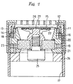
- a conventional condenser microphone of this kind is shown in Fig. 1.
- Diaphragm retaining rings 13 and 14 are urged and held against the flange 12 on the inside thereof.
- the peripheral portion of a diaphragm 15 is clamped between the diaphragm retaining rings 13 and 14.
- a cylindrical presser 16 is pressed forwardly against the back of the diaphragm 15.
- the inner surface of the housing 11 has cut therein screw threads 17, with which a ring-shaped screw 18 is threadably engaged to fix the diaphragm retaining rings 13 and 14 while pressing them forwardly.
- ring-shaped screws 19 and 21 are threadably engaged with the screw threads 17, by which the cylindrical presser 16 is urged against the diaphragm 15, applying thereto a desired tensile force.
- a back electrode 22 is disposed just behind the diaphragm 15 in opposing relation thereto and supported at the rear by a ring-shaped support plate 23 of an insulating material, which is in turn held by the ring-shaped screw 21 threadably engaged with the screw threads 17.
- a spacer 20 is interposed between the cylindrical presser 16 and the support plate 23, defining the space between the diaphragm 15 and the back electrode 22.
- a ring-shaped screw 24 is threadably engaged with the screw threads 17 behind the ring-shaped screw 21.
- the back electrode 22 has a terminal 25.
- the housing 11 is covered all over its front open end with a grid 26.
- the back electrode 22 is deposited with an electret film 27 opposite the diaphragm 15.
- the diaphragm 15 of the conventional condenser microphone is pressed by the cylindrical presser 16 and is held taut with a predetermined tensile force. Since the condenser microphone has incorporated therein the cylindrical presser, it is inevitably bulky, calls for many assembling steps, and hence is cumbersome to assemble and expensive. Moreover, the diaphragm 15 is held taut by the cylindrical presser 16, which is retained by the ring-shaped screw 19 in the housing 11; so that the tension of the diaphragm 15 is liable to vary with a change in ambient temperature unless the diaphragm retaining rings 13 and 14, the ring-shaped screw 18, the cylindrical presser 16 and the ring-shaped screw 19 are made of the same material. Besides, there is a fear that a change in the tension of the diaphragm 15 results from a possible change in the pressure applied thereto by the cylindrical presser 16 although the latter is fixed by the two screws 19 and 21.
- the diaphragm 15 and the back electrode 22 must be spaced a predetermined distance apart with high precision.
- the cylindrical presser 16 and the back electrode 22 are finished to the same height (the length in the direction parallel to the axes thereof) through precision polishing, and then the space between the diaphragm 15 and the back electrode 22 is defined by the thickness of the spacer 20.
- high precision is needed in machining the cylindrical presser 16 and the back electrode 22, and the spacer 20 is needed, which leads to an increase in the number of parts used. These factors inevitably raise the cost of the microphone.
- a condenser microphone similar to that shown in Fig. 1 is also disclosed in JP-U-56-108699.
- This microphone also employs a cylindrical presser 2, and hence has the same defect as that of the condenser microphone shown in Fig. 1.
- An object of the present invention is to provide a simple-structured diaphragm unit which has a diaphragm held with required tension by itself and a method of making such a diaphragm unit.
- Another object of the present invention is to provide a diaphragm unit designed so that the tension of the diaphragm is essentially insusceptible to the influence of temperature in the microphone housing.
- Another object of the present invention is to provide a simple-structured condenser microphone having a diaphragm unit built therein.
- Yet another object of the present invention is to provide a simple-structured condenser microphone which permits easy adjustment of the condenser gap.
- the diaphragm unit includes a first ring, a second ring and a diaphragm held with a predetermined tensile force and having its peripheral portion gripped between the first and second rings.
- the two rings and the diaphragm are bonded together through electron beam welding.
- the diaphragm unit of the present invention dispenses with the cylindrical presser for applying tension to the diaphragm, and hence permits the fabrication of a condenser microphone which is small in the number of parts therefor and small in size accordingly.
- the first ring can be used also as the microphone housing, in which case the microphone can be further miniaturized.
- screw threads can be cut in the peripheral surface of the plate, so that it is possible to obtain a microphone which allows ease in adjusting the condenser gap.
- the diaphragm is mounted on a jig and attached thereto at its marginal portion; the first ring is urged, by a presser engaged with the jig, against the diaphragm to apply tension thereto; the second ring is mounted on the first ring with the diaphragm gripped therebetween; and the first and second rings and the diaphragm are welded together by electron beam welding.
- a diaphragm unit is obtained in which the diaphragm is sandwiched between the first and second rings and held with predetermined tension by itself.
- the diaphragm is held at its marginal portion between the first and second rings and coupled thereto through electron beam welding and then the first and second rings are expanded to apply tension to the diaphragm. Also in this case, the diaphragm of the diaphragm unit is held with predetermined tension by itself. Accordingly, no cylindrical presser is needed in the case where the diaphragm unit is built in the condenser microphone.
- the diaphragm 15 made of a metal such as titanium, a titanium-alloy or nickel-alloy, about 1 to 6 ⁇ m thick, is mounted on a jig 31 and held thereto at its peripheral portion.
- the jig 31 is cylindrical in shape and has a flange 32 extending from the inner edge of its front open end and the peripheral portion of the diaphragm 15 is clamped to the back of the flange 32 by means of a diaphragm clamping ring 33.
- the inner peripheral surface of the jig 31 has cut therein screw threads 34, with which a fixing ring 35 is threadably engaged, thereby urging the diaphragm clamping ring 33 against the flange 32. In this way, the diaphragm 15 is fixedly mounted on the jig 31.
- a presser 36 is screwed into the jig 31 to press a first ring 37 against the diaphragm 15, applying thereto tension.
- the presser 36 is cylindrical in shape and has on its front end face the first ring 37 disposed in position and at its rear end a threaded flange 38 formed integrally therewith, the threaded flange being threadably engaged with the screw threads 34.
- the first ring 37 can be pressed forward. In this fashion, the first ring 37 is fed forward until the tension of the diaphragm 15 reaches a predetermined value.
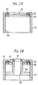
- a second ring 39 is disposed opposite the first ring 37 with the diaphragm 15 gripped therebetween as shown in Fig. 2C; namely, the diaphragm 15 is sandwiched between the first and second rings 37 and 39.
- the second ring 39 is pressed by a supplementary means 41 against the first ring 37.
- the structure thus assembled as shown in Fig. 2C is then placed in a vacuum chamber 42 as depicted in Fig. 2D.
- the vacuum chamber 42 is evacuated to a vacuum of around 1 ⁇ 10 ⁇ 2 Torr, in which the boundary between the diaphragm 15 and the second ring 39 is irradiated with an electron beam (0.3 mm or less in spot diameter) from an electron beam gun (EBG) 40 and at the same time the entire structure including the jig 31, the supplementary means 41, etc. is turned about the center of the structure, thereby welding the diaphragm 15 to the first and second rings 37 and 39 over the entire circumference thereof.
- the time for irradiation with the electron beam at each point may be one second or so. To ensure good welding, it is desirable that the diaphragm 15 and the first and second rings 37 and 39 be made of the same material.
- the diaphragm 15 retaining substantially the same tension as that applied thereto before the welding is integrated with the first and second rings 37 and 39, providing the diaphragm unit. Since the diaphragm 15 gripped by the first and second rings 37 and 39 is held with predetermined tension by itself, there is no need of using such a conventional tension applying means as the cylindrical presser when the diaphragm unit is incorporated into the condenser microphone.
- Fig. 3 is a diagram, corresponding to Fig. 2D, which illustrates a second embodiment of the present invention in which the first ring 37 is used also as the microphone housing. That is, the first ring 37 is a cylindrical member in this example. A description will be given later of an example of the condenser microphone which employs the first ring serving also as the microphone housing.
- Figs. 4A and 4B illustrate a third embodiment of the present invention.
- the first ring 37 is mounted on a first fixture 45; the diaphragm 15 is disposed across the first ring 37; the second ring 39 is placed on the first ring 37 with the diaphragm 15 gripped therebetween; and a second fixture 46 is mounted on the second ring 39.
- the diaphragm 15 which is not yet given tension is held between the first and second rings 37 and 39.
- the structure thus assembled is placed in the vacuum chamber 42 evacuated to a vacuum of approximately 1 ⁇ 10 ⁇ 2 Torr, and the point of contact between the diaphragm 15 and the first ring 37 or second ring 39 is irradiated with the electron beam 43 while at the same time the fixtures 45 and 46 are rotated together.
- the diaphragm 15 is welded to the first and second rings 37 and 39.
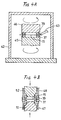
- first and second rings 37 and 39 are expanded in diameter to give predetermined tension to the diaphragm 15. This is carried out in a manner such, for example, as shown in Fig. 4B.
- Auxiliary jigs 47 and 48 are prepared which are each cylindrical in shape and has at one end a small-diametered portion.
- the small-diametered portions of the auxiliary jigs 47 and 48 are fitted into the first and second rings 37 and 39, respectively, and expanding jigs 51 and 52, each having at one end a truncated conical portion, are pressed into the auxiliary jigs 47 and 48, respectively, with the peripheral surfaces of their truncated conical portions against inner edges of the auxiliary jigs 47 and 48 between their large- and small-diametered portions.
- the expanding jigs 51 and 52 toward each other, the diameters of the first and second rings 37 and 39 are expanded through the expanding jigs 51 and 52, applying tension to the diaphragm 15.
- a titanium-base alloy of a ⁇ -type crystal structure is suitable for the diaphragm 15 and the first and second rings 37 and 39 because of its high expansibility.
- the frequency band of the microphone can freely be chosen by a suitable selection of the tension which is applied to the diaphragm 15.
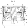
- Fig. 5 illustrates an example of a condenser microphone employing the diaphragm unit 55 obtained by the method described above in respect of Figs. 2A to 2D or Figs. 4A and 4B.
- the contact end faces of the first and second rings 37 and 39 are sloped and the inner diameter of the sloped end face of the first ring 37 is smaller than the inner diameter of the sloped end face of the second ring 39, and accordingly the first ring 37 protrudes inwardly of the second ring 39. Consequently, the peripheral portion of the diaphragm 15 is supported by the inner marginal edge of the sloped end face of the first ring 37.
- the first ring 37 has a stepped portion 40 formed in its inner peripheral surface at the backward portion thereof.
- the diaphragm unit 55 which has the diaphragm 15 clamped at its marginal portion between the first and second rings 37 and 39 and welded thereto through electron beam welding, is held against the back of the flange 12 of the housing 11.
- the back electrode 22 is disposed opposite the diaphragm 15, the back electrode 22 being deposited over the entire area of its front surface with the electret film 27.
- a flange 22b extending from a support rod 22a of the back electrode 22 is partly received in a centrally-disposed through hole 23a of the ring-shaped support plate 23 made of an insulating material, with the support rod 22a of the back electrode projecting out of the through hole on the back of the support plate 23.
- the rear end portion of the support rod 22a has screw threads and is screwed into a tapped hole of a terminal 25, and by the tightening of the threaded terminal 25 the back electrode 22 is fixedly secured to the support plate 23.
- the support plate 23 is urged and held against the stepped portion 40 in the inner peripheral surface of the first ring 37 with the spacer 20 held between them.
- An auxiliary ring 57 is held against the support plate 23 at its back and outer peripheral surface, and the ring-shaped screw 24 is urged against the back of the auxiliary ring 57.
- the ring-shaped screw 24 is threadably engaged with the screw threads 17 of the housing 11.
- the first ring 37 has a slit 58 extending axially from its rear end to form a channel 59 which extends to a space 28 behind the back electrode 22.
- the channel 59 communicates with the outside through an air hole 61 made in the housing 11.
- a washer 62 is interposed between the support plate 23 and the terminal 25.
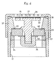
- Fig. 6 illustrates an example of a condenser microphone which employs the diaphragm produced by the embodiment described previously with regard to Fig. 3, the parts corresponding to those in Fig. 5 being identified by the same reference numerals.
- the first ring 37 is cylindrical in shape and used to form the microphone housing, in which the back electrode 22 and the support plate 23 therefor are disposed and the auxiliary ring 57 is also housed.
- the inner peripheral surface of the first ring 37 has at its rear portion the screw threads 17, with which the ring-shaped screw 24 is threadably engaged, holding the back electrode 22 in the first ring 37.
- the first ring 37 is capped with the grid 26 disposed opposite the diaphragm 15.
- Fig. 7 illustrates a fourth embodiment of the diaphragm unit of the present invention.
- the diaphragm 15 is joined along its entire marginal portion to the first ring 37 on one side thereof. Where the diaphragm 15 is a metallic one, it is welding to the first ring 37 through electron beam welding, and where the diaphragm 15 is one that is produced by coating a polyester or similar synthetic resin film with a metallic layer, it is bonded to the first ring 37 by use of an adhesive.
- the second ring 39 made of metal is welded by electron beam welding to the first ring 37 with the diaphragm 15 sandwiched therebetween.
- the second ring 39 may preferably be made of the same material as that of the first ring 37.
- the second ring 39 has edge flanges 39a and 39b raised about its inner and outer peripheries along the inner and outer peripheries of the first ring 37, respectively.
- the inner and outer edge flanges 39a and 39b define therebetween a recess for receiving the first ring 37.
- the diaphragm 15 is urged by the inner edge flange 39a forwardly into the first ring 37 and held tight with predetermined tension.
- the outer edge flange 39b of the second ring 39 is welded by electron beam welding to the outer peripheral surface of the first ring 37 over the entire circumference thereof.
- a diaphragm unit 55 starts with placing the first ring 37 on the jig 36 in the vacuum chamber 42 evacuated to a vacuum of about 10 ⁇ 2 Torr as shown in Fig. 8A, for example.
- the metallic diaphragm 15, free from tension, is placed substantially flat on one side of the first ring 37 and the fixture 41 is pressed against the first ring 37 from above. Then the metallic diaphragm 15 is welded to the first ring 37 over the entire circumference thereof by applying the electron beam 43 obliquely aslant to them.
- the second ring 39 is mounted on a jig 36', the first ring 37 having spread thereon the metallic diaphragm 15 is disposed on the second ring 39 with the diaphragm 15 upside down, and the first ring 37 is urged against the second ring 39 from above by the jig 41 so that the inner edge flange 39a of the second ring 39 protrudes into the first ring 37, applying predetermined tension to the diaphragm 15.
- the electron beam 43 is applied diagonally to the contact portion between the first and second rings 37 and 39 to weld them over the entire circumference thereof.
- the diaphragm unit 55 is obtained which has the metallic diaphragm 15 spread with predetermined tension.
- the first and second rings 37 and 39 may also be exchanged with each other.
- Fig. 9 illustrates an example of a microphone which employs the diaphragm unit 55 which is a modified form of the embodiment shown in Figs. 7, 8A and 8B.
- the housing 11 has the flange 12 extending inwardly from its front marginal edge, and the diaphragm unit 55 is housed in the housing 11, with the second ring 39 held against the flange 12.
- the first ring 37 is fixed to the housing 11 by a ring-shaped screw 44 threadably engaged with the screw threads 17 of the housing 11.
- the back electrode 22 is disposed opposite the diaphragm 15, the back electrode 22 being coated with the electret film 27 on the side facing the diaphragm 15.
- the support plate 23 is received in the stepped portion made in the interior surface of the first ring 37, with the spacer 20 held between them, and the back electrode 22 is supported by the support plate 23.
- the support plate 23 is fixedly held by the ring-shaped screw 24 through the auxiliary ring 57.
- the ring-shaped screw 24 is threadably engaged with the screw threads 17.
- the terminal 25 is thread-mounted on the rear of the back electrode 22 with the washer 62 held against the support plate 23.
- Fig. 10 illustrates another embodiment of the condenser microphone of the present invention, in which the parts corresponding to those in Fig. 9 are identified by the same reference numerals.
- the support plate 23 of an insulating material for supporting the back electrode 22 is made of machinable crystalline glass and the support plate 23 has screw threads cut in its outer peripheral surface over the entire circumference thereof.
- the support plate 23 has an air hole 53 which is made therethrough by a laser beam, as required. Further, the support plate 23 has a centrally-disposed through hole, through which the terminal 25 is screwed into the back electrode 22.
- the diaphragm unit 55 mounted in the housing 11 has a structure in which the diaphragm 15 is given predetermined tension, has its peripheral portion gripped between the first and second rings 37 and 39 and is welded thereto over the entire circumference thereof by such a method as described previously in connection with Figs. 2A and 2B or Fig. 3.
- the inner peripheral surface of the first ring 37 has cut therein screw threads, with which the support plate 23 is threadably engaged.
- the depth into which the support plate 23 is screwed is determined by a predetermined electrostatic capacitance between the diaphragm 15 and the back electrode 22.
- a ring-shaped screw 44 is threadably engaged with the screw threads 17 of the housing 11 at the back of the first ring 37, by which the first ring 37 is fixedly held against the housing 11 and the support plate 23 is urged and fixed through a bushing 63 made of an elastic resin.
- the machinable crystalline glass herein mentioned is one that is now on sale, for example, under the trademark "MACOR” by Corning Glass Inc. of the United States; this is an isotropic compound material composed of glass and ceramic, which is produced by melting raw materials, molding the melt into a desired shape such as a sheet, bar or rod, and heat treating the molding so that crystallites of synthetic mica are grown randomly in glass.
- MACOR Corning Glass Inc. of the United States
- This machinable crystalline glass has a coefficient of thermal expansion of 9.4 x 10 ⁇ 6/°C which is relatively close to that of a titanium alloy, a high volume resistivity of 1016 ⁇ cm or more, excellent in insulating property, and a coefficient of water absorption of zero, excellent in water resisting property; besides, this glass is machinable and can be cut into complex shapes, including screw cutting.
- optical glass has been employed for the support plate 23 for fixing the back electrode 22 because it has a coefficient of thermal expansion substantially equal to that of the material (titanium or a titanium alloy) for the back electrode 22, a high volume resistivity, a high breakdown voltage and zero coefficient of water absorption.
- the optical glass is difficult of machining such as screw cutting and drilling of thin holes, and is costly.
- the machinable crystalline glass is used for the support plate 23 for supporting the back electrode 22, screw threads can be cut in the outer periphery of the support plate for threaded engagement with the inner peripheral surface of the first ring 37 as shown in Fig.
- the gap between the diaphragm 15 and the back electrode 22 can easily be adjusted simply by turning the support plate 23.
- the support plate 23 can easily be machined, the air hole 53 as thin as 0.2 mm, for example, can be made in the support plate 23 by a laser beam.
- the use of the machinable crystalline glass enables the air hole 53 of a desired size to be made in the support plate 23 at a desired position and thus allows a wide freedom of design.
- the microphone since the diaphragm is held taut between and welded or bonded to the first and second rings, the microphone does not require any presser for applying tension to the diaphragm and is small in the number of parts therefor, easy of assembling, small in size and low-cost accordingly.
- the first ring is used also as the microphone housing, the number of parts used is further reduced, permitting further miniaturization of the microphone and further reduction of its manufacturing costs.
- the tension of the diaphragm is not easily reduced and is held at a predetermined value.
- titanium or a titanium alloy can be used for the diaphragm unit 55 and stainless steel for the housing 11; namely, materials of different coefficients of thermal expansion but suited to respective parts can be utilized.
- the tension of the diaphragm is free from the influence of thermal expansion of the housing 11, the auxiliary ring 57, etc. even if temperature varies. Accordingly, the housing 11, the auxiliary ring 57, etc. and the first and second rings need not be made of the same material, and this also affords the reduction of the manufacturing costs of the condenser microphone.
Landscapes
- Engineering & Computer Science (AREA)
- Physics & Mathematics (AREA)
- Acoustics & Sound (AREA)
- Signal Processing (AREA)
- Manufacturing & Machinery (AREA)
- Electrostatic, Electromagnetic, Magneto- Strictive, And Variable-Resistance Transducers (AREA)
Abstract
Claims (22)
- Unité à membrane destinée à un microphone à condensateur, dans laquelle une membrane métallique (15) est serrée, au niveau de sa partie périphérique, entre des première et seconde bagues métalliques (37, 39), les bagues et la membrane sont unies par soudage par faisceau électronique et la membrane est maintenue par lesdites bagues sous une tension prédéterminée.
- Unité à membrane selon la revendication, dans laquelle les bagues (37, 39) et la membrane (15) sont réalisées à partir de la même matière.
- Unité à membrane selon la revendication 1 ou 2, dans laquelle la partie périphérique de la membrane (15) est soudée aussi bien à ladite première bague (37) qu'à ladite seconde bague (39) par soudage par faisceau électronique.
- Unité à membrane selon la revendication 1, 2 ou 3, dans laquelle l'une (39) des bagues (37, 39) comporte, solidaire de celle-ci, une bride formant rebord / bord (39a) surélevée autour de sa périphérie interne le long de toute la périphérie interne de l'autre bague (37) et faisant saillie vers l'intérieur de l'autre bague.
- Unité à membrane selon l'une quelconque des revendications précédentes, dans laquelle les faces d'extrémité de contact des bagues (37, 39) sont inclinées, la partie marginale interne de la face d'extrémité inclinée de l'une des bagues faisant saillie vers l'intérieur de l'autre bague de sorte que le diamètre interne de la face d'extrémité inclinée de ladite bague est inférieur au diamètre interne de la face d'extrémité inclinée de l'autre bague.
- Unité à diaphragme selon la revendication 4 ou 5, dans laquelle l'une (39) des bagues (37, 39) comporte, solidaire de celle-ci, une bride formant rebord (39b) surélevée autour de sa périphérie externe et s'étendant dans sa direction axiale le long de toute la périphérie externe de l'autre bague (37).
- Unité à diaphragme selon la revendication 1, dans laquelle la partie périphérique de la membrane (15) est maintenue en contact avec un côté de l'une (37) desdites bagues et est soudée à cette dernière par soudage par faisceau électronique, l'autre bague (39) comporte une bride formant rebord interne (39a) surélevée autour de sa périphérie interne le long de toute la périphérie interne de ladite bague (37) et pousse ladite membrane (15), par ladite bride formant bord interne (39a) vers l'autre côté de ladite bague (37), et ladite autre bague (39) est soudée à ladite bague (37) par soudage par faisceau électronique.
- Unité à membrane selon la revendication 7, dans laquelle ladite autre bague (39) comporte, solidaire de celle-ci, une bride formant rebord (39b) surélevée autour de sa périphérie externe et s'étendant dans sa direction axiale le long de toute la périphérie externe de ladite bague (37), le bord marginal de ladite bride formant rebord étant soudé à la surface périphérique externe de ladite bague par soudage par faisceau électronique.
- Unité à membrane selon l'une quelconque des revendications précédentes, dans laquelle l'une ou l'autre desdites bagues (37, 39) est un élément cylindrique plus long dans la direction axiale que l'autre et forme un boîtier d'un microphone à condensateur.
- Unité à diaphragme selon l'une quelconque des revendications précédentes, dans lequel l'une ou l'autre desdites bagues (37, 39) est un élément cylindrique plus long dans la direction axiale que l'autre et présente des filetages de vis réalisés dans sa surface périphérique interne.
- Unité à membrane selon l'une quelconque des revendications précédentes, dans laquelle l'une ou l'autre desdites bagues (37, 39) est un élément cylindrique plus long dans la direction axiale que l'autre et présente une partie en gradin dans sa partie périphérique interne.
- Procédé de fabrication d'une unité à membrane selon l'une quelconque des revendications 3 à 6, comportant l'étape consistant:
à maintenir la partie périphérique d'une membrane métallique (15) sur un gabarit (31);
à appliquer une première bague métallique (37) à l'aide de moyens de pression venant en prise avec le gabarit (31) contre la membrane (15) pour appliquer à cette dernière une tension prédéterminée;
à serrer la membrane (15) entre la première bague (37) et une seconde bague métallique (39); et
à souder ensemble les première et seconde bagues (37, 39) et la membrane par soudage par faisceau électronique. - Procédé de fabrication d'une unité à membrane selon l'une quelconque des revendications 3 à 6, comportant les étapes consistant:
à serrer une membrane métallique (15) entre des première et seconde bagues métalliques (37, 39);
à souder les première et seconde bagues (37, 39) à la membrane (15) par soudage par faisceau électronique; et
à faire augmenter les diamètres des première et seconde bagues (37, 39) pour appliquer une tension prédéterminée à la membrane. - Procédé de fabrication d'une unité à membrane selon la revendication 7 ou 8, comportant les étapes consistant:
à souder une membrane métallique (15) au bord marginal externe d'une face d'extrémité d'une première bague métallique (37) par soudage par faisceau électronique;
à appliquer une tension prédéterminée à la membrane en appliquant contre elle une bride formant rebord (39a) surélevée autour de la périphérie interne d'une face d'extrémité d'une seconde bague métallique (39), et
à souder une bride formant rebord (39b) surélevée autour de la périphérie externe de la seconde bague (39) à la surface périphérique externe de la première bague par soudage par faisceau électronique. - Procédé selon la revendication 12,13 ou 14, dans lequel la première bague (37) forme un boîtier d'un microphone à condensateur.
- Microphone à condensateur comportant:
une unité à diaphragme selon la revendication 9;
une plaque support (23) réalisée en une matière isolante disposée en prise avec ladite bague (37) de l'unité à membrane;
une électrode arrière (22) maintenue sur la plaque support (32) et espacée d'une distance prédéterminée de la membrane (15); et
des moyens de fixation (24, 57) disposés derrière la plaque support (23) pour fixer la plaque support à ladite bague (37). - Microphone à condensateur selon la revendication 16, dans lequel ladite bague (37) est un élément cylindrique et comporte une partie en gradin dans sa surface périphérique interne, la plaque support (23) étant appliquée contre la partie en gradin, une entretoise (20) étant maintenue entre elles.
- Microphone à condensateur selon la revendication 16 ou 17, dans lequel l'unité à membrane est logée dans un boîtier cylindrique (11) de sorte qu'elle soit au contact avec le côté interne d'une bride (12) s'étendant à partir du bord interne avant du boîtier.
- Microphone à condensateur selon la revendication 16 ou 17, dans lequel ladite bague (37) est un élément cylindrique dont la partie arrière s'étend dans sa direction axiale, la partie arrière de ladite bague comporte des filetages de vis réalisés dans sa surface périphérique interne pour former un trou taraudé, et lesdits moyens de fixation (24) sont vissés dans le trou taraudé derrière la plaque support (23).
- Microphone à condensateur selon la revendication 19, dans lequel la partie avant de l'unité à diaphragme est reçue dans un couvercle cylindrique (26) dans lequel est percé au moins un trou.
- Microphone à condensateur selon la revendication 16 ou 19, dans lequel ladite plaque support (23) est réalisée en verre cristallin apte à être usiné et s'engage par vissage avec ladite bague (37) de l'unité à membrane.
- Microphone à condensateur selon la revendication 21, dans lequel la plaque support (23) comporte un trou de ventilation (53) par l'intermédiaire duquel un espace situé derrière l'électrode arrière (22) communique avec l'extérieur.
Applications Claiming Priority (7)
| Application Number | Priority Date | Filing Date | Title |
|---|---|---|---|
| JP5101887A JPH0642759B2 (ja) | 1987-03-04 | 1987-03-04 | コンデンサマイクロホンの振動板及びその製造法 |
| JP51018/87 | 1987-03-04 | ||
| JP113223/87U | 1987-07-22 | ||
| JP11322387U JPS6418897U (fr) | 1987-07-22 | 1987-07-22 | |
| JP1987113224U JP2514204Y2 (ja) | 1987-07-22 | 1987-07-22 | 静電形マイクロホン |
| JP113224/87U | 1987-07-22 | ||
| PCT/JP1988/000236 WO1988006832A1 (fr) | 1987-03-04 | 1988-03-03 | Unite de diaphragame d'un microphone a condensateur, procede de production, et microphone a condensateur |
Publications (3)
| Publication Number | Publication Date |
|---|---|
| EP0305540A1 EP0305540A1 (fr) | 1989-03-08 |
| EP0305540A4 EP0305540A4 (en) | 1991-07-03 |
| EP0305540B1 true EP0305540B1 (fr) | 1994-11-23 |
Family
ID=27294167
Family Applications (1)
| Application Number | Title | Priority Date | Filing Date |
|---|---|---|---|
| EP88902236A Expired - Lifetime EP0305540B1 (fr) | 1987-03-04 | 1988-03-03 | Unite de diaphragame d'un microphone a condensateur, procede de production, et microphone a condensateur |
Country Status (4)
| Country | Link |
|---|---|
| US (1) | US5014322A (fr) |
| EP (1) | EP0305540B1 (fr) |
| DE (1) | DE3852156T2 (fr) |
| WO (1) | WO1988006832A1 (fr) |
Cited By (1)
| Publication number | Priority date | Publication date | Assignee | Title |
|---|---|---|---|---|
| EP1762117B1 (fr) * | 2004-05-19 | 2009-08-19 | Sennheiser electronic GmbH & Co. KG | Microphone a condensateur |
Families Citing this family (8)
| Publication number | Priority date | Publication date | Assignee | Title |
|---|---|---|---|---|
| AT403751B (de) * | 1996-06-19 | 1998-05-25 | Akg Akustische Kino Geraete | Verfahren zur herstellung einer membran für einen elektroakustischen wandler |
| AT413924B (de) * | 2001-04-24 | 2006-07-15 | Akg Acoustics Gmbh | Mikrofonkapsellagerung |
| US7065224B2 (en) * | 2001-09-28 | 2006-06-20 | Sonionmicrotronic Nederland B.V. | Microphone for a hearing aid or listening device with improved internal damping and foreign material protection |
| US7415121B2 (en) * | 2004-10-29 | 2008-08-19 | Sonion Nederland B.V. | Microphone with internal damping |
| JP4659519B2 (ja) * | 2005-05-25 | 2011-03-30 | 株式会社オーディオテクニカ | 振動板組立体の製造方法およびコンデンサマイクロホン |
| DE102006042855B4 (de) * | 2006-09-13 | 2016-01-14 | Sennheiser Electronic Gmbh & Co. Kg | Kondensatormikrofon |
| CN103491472A (zh) * | 2012-06-12 | 2014-01-01 | 深圳富泰宏精密工业有限公司 | 话筒组件及应用其的便携式电子装置 |
| CN112367598A (zh) * | 2020-10-26 | 2021-02-12 | 中国电子科技集团公司第三研究所 | 一种高声压级低失真度传声器及其振膜的制造方法 |
Family Cites Families (25)
| Publication number | Priority date | Publication date | Assignee | Title |
|---|---|---|---|---|
| US2500643A (en) * | 1946-12-07 | 1950-03-14 | Bell Telephone Labor Inc | Condenser transducer independent of ambient atmospheric conditions |
| US2787671A (en) * | 1952-10-06 | 1957-04-02 | Schall Technik Dr Ing Karl Sch | Microphone arrangement |
| DE1011467B (de) * | 1954-08-13 | 1957-07-04 | Schoeps Dr Ing Karl | Umschaltbares Kondensator-Mikrophon |
| JPS5110924A (fr) * | 1974-07-16 | 1976-01-28 | Sony Corp | |
| US3958662A (en) * | 1975-02-18 | 1976-05-25 | Bell Telephone Laboratories, Incorporated | Tensioned diaphragm mounting for an electroacoustic transducer |
| JPS5221053A (en) * | 1975-08-11 | 1977-02-17 | Sando Iron Works Co Ltd | Drying of pva recovered from waste water and apparatus for the same |
| JPS5223330A (en) * | 1975-08-13 | 1977-02-22 | Saima Purodakutsu Corp | Portable case for photographic camera of pneumatic protection |
| JPS5252581A (en) * | 1975-10-25 | 1977-04-27 | Fujitsu Ltd | Semiconductor device |
| JPS5654711Y2 (fr) * | 1976-06-11 | 1981-12-19 | ||
| US4070741A (en) * | 1976-09-27 | 1978-01-31 | Genrad Inc. | Method of making an electret acoustic transducer |
| JPS5756640Y2 (fr) * | 1978-09-30 | 1982-12-06 | ||
| US4258235A (en) * | 1978-11-03 | 1981-03-24 | Electro-Voice, Incorporated | Pressure gradient electret microphone |
| JPS56108699U (fr) * | 1980-01-21 | 1981-08-22 | ||
| JPS56108699A (en) * | 1980-01-31 | 1981-08-28 | Toyoda Automatic Loom Works | Turning gear for fork lift |
| AT366862B (de) * | 1980-07-28 | 1982-05-10 | Akg Akustische Kino Geraete | Elektroakustischer wandler nach dem zweiwegprinzip |
| JPS5744399A (en) * | 1980-08-29 | 1982-03-12 | Sony Corp | Electrostatic type electroacoustic transducer |
| JPS57107700A (en) * | 1980-12-25 | 1982-07-05 | Matsushita Electric Works Ltd | Electrostatic type ultrasonic wave oscillator |
| JPS622879Y2 (fr) * | 1981-03-25 | 1987-01-22 | ||
| CH642504A5 (en) * | 1981-06-01 | 1984-04-13 | Asulab Sa | Hybrid electroacoustic transducer |
| JPS58114600A (ja) * | 1981-12-26 | 1983-07-07 | Toshiba Corp | 静電型マイクロホン |
| DK152639C (da) * | 1982-10-08 | 1989-03-13 | Niels Martin Jensen | Fremgangsmaade og apparat til udspaending og fastgoerelse af en tynd folie |
| FR2563959B1 (fr) * | 1984-05-04 | 1990-08-10 | Lewiner Jacques | Perfectionnements aux transducteurs electro-acoustiques a electret |
| JPS6166500A (ja) * | 1984-09-10 | 1986-04-05 | Power Reactor & Nuclear Fuel Dev Corp | コンデンサ型耐高温・耐放射線マイクロホン |
| US4568414A (en) * | 1984-09-21 | 1986-02-04 | At&T Technologies, Inc. | Methods and apparatus for tensioning sheet material |
| JP2576727B2 (ja) * | 1991-10-14 | 1997-01-29 | 三菱電機株式会社 | 自動焦点調節装置 |
-
1988
- 1988-03-03 EP EP88902236A patent/EP0305540B1/fr not_active Expired - Lifetime
- 1988-03-03 DE DE3852156T patent/DE3852156T2/de not_active Expired - Fee Related
- 1988-03-03 US US07/320,333 patent/US5014322A/en not_active Expired - Fee Related
- 1988-03-03 WO PCT/JP1988/000236 patent/WO1988006832A1/fr active IP Right Grant
Cited By (1)
| Publication number | Priority date | Publication date | Assignee | Title |
|---|---|---|---|---|
| EP1762117B1 (fr) * | 2004-05-19 | 2009-08-19 | Sennheiser electronic GmbH & Co. KG | Microphone a condensateur |
Also Published As
| Publication number | Publication date |
|---|---|
| WO1988006832A1 (fr) | 1988-09-07 |
| US5014322A (en) | 1991-05-07 |
| EP0305540A1 (fr) | 1989-03-08 |
| DE3852156T2 (de) | 1995-05-11 |
| DE3852156D1 (de) | 1995-01-05 |
| EP0305540A4 (en) | 1991-07-03 |
Similar Documents
| Publication | Publication Date | Title |
|---|---|---|
| US5854846A (en) | Wafer fabricated electroacoustic transducer | |
| EP0305540B1 (fr) | Unite de diaphragame d'un microphone a condensateur, procede de production, et microphone a condensateur | |
| US4582961A (en) | Capacitive transducer | |
| US4014091A (en) | Method and apparatus for an electret transducer | |
| US6014800A (en) | Method of making a pressure transducer having a tensioned diaphragm | |
| EP0531613A2 (fr) | Microphone à électrète | |
| EP0051832B1 (fr) | Transducteur piézoélectrique céramique | |
| US4368400A (en) | Piezoelectric ultrasonic transducer mounted in a housing | |
| CN1129980A (zh) | 电容压力传感器 | |
| US4891843A (en) | Electret microphone | |
| KR20000006110A (ko) | 압전음향부품 | |
| US5038459A (en) | Method of fabricating the diaphragm unit of a condenser microphone by electron beam welding | |
| US5570428A (en) | Transducer assembly | |
| US3588552A (en) | Prestressed piezoelectric audio transducer | |
| US4042438A (en) | Method of assembling a diaphragm assembly for an electro-acoustic transducer | |
| JP2000050394A (ja) | エレクトレットコンデンサマイクロホン | |
| US4697334A (en) | Method of producing electroacoustic converters, preferably microphones, and converters produced according to the method | |
| CN100377622C (zh) | 背极驻极体电容式传声器制造方法 | |
| JP2008147899A (ja) | エレクトレットコンデンサマイクロホンユニットの構成部材の製造方法 | |
| US4215249A (en) | Method and device for controlling wrinkles in a vibratile diaphragm | |
| JPH053599A (ja) | コンデンサマイクロホン及びその製造方法 | |
| JPH0642759B2 (ja) | コンデンサマイクロホンの振動板及びその製造法 | |
| JPS6239600B2 (fr) | ||
| US4401858A (en) | Method for controlling wrinkles in a vibratile diaphragm | |
| JP2995240B2 (ja) | コンデンサマイクロホン |
Legal Events
| Date | Code | Title | Description |
|---|---|---|---|
| PUAI | Public reference made under article 153(3) epc to a published international application that has entered the european phase |
Free format text: ORIGINAL CODE: 0009012 |
|
| 17P | Request for examination filed |
Effective date: 19881028 |
|
| AK | Designated contracting states |
Kind code of ref document: A1 Designated state(s): DE GB |
|
| A4 | Supplementary search report drawn up and despatched |
Effective date: 19910516 |
|
| AK | Designated contracting states |
Kind code of ref document: A4 Designated state(s): DE GB |
|
| RAP1 | Party data changed (applicant data changed or rights of an application transferred) |
Owner name: HOSIDEN CORPORATION |
|
| 17Q | First examination report despatched |
Effective date: 19930128 |
|
| GRAA | (expected) grant |
Free format text: ORIGINAL CODE: 0009210 |
|
| AK | Designated contracting states |
Kind code of ref document: B1 Designated state(s): DE GB |
|
| REF | Corresponds to: |
Ref document number: 3852156 Country of ref document: DE Date of ref document: 19950105 |
|
| PLBE | No opposition filed within time limit |
Free format text: ORIGINAL CODE: 0009261 |
|
| STAA | Information on the status of an ep patent application or granted ep patent |
Free format text: STATUS: NO OPPOSITION FILED WITHIN TIME LIMIT |
|
| 26N | No opposition filed | ||
| PGFP | Annual fee paid to national office [announced via postgrant information from national office to epo] |
Ref country code: GB Payment date: 20000301 Year of fee payment: 13 |
|
| PGFP | Annual fee paid to national office [announced via postgrant information from national office to epo] |
Ref country code: DE Payment date: 20000330 Year of fee payment: 13 |
|
| PG25 | Lapsed in a contracting state [announced via postgrant information from national office to epo] |
Ref country code: GB Free format text: LAPSE BECAUSE OF NON-PAYMENT OF DUE FEES Effective date: 20010303 |
|
| GBPC | Gb: european patent ceased through non-payment of renewal fee |
Effective date: 20010303 |
|
| PG25 | Lapsed in a contracting state [announced via postgrant information from national office to epo] |
Ref country code: DE Free format text: LAPSE BECAUSE OF NON-PAYMENT OF DUE FEES Effective date: 20020101 |