EP0305394B1 - Arrangement for liquid treatment of pulp - Google Patents
Arrangement for liquid treatment of pulp Download PDFInfo
- Publication number
- EP0305394B1 EP0305394B1 EP87903455A EP87903455A EP0305394B1 EP 0305394 B1 EP0305394 B1 EP 0305394B1 EP 87903455 A EP87903455 A EP 87903455A EP 87903455 A EP87903455 A EP 87903455A EP 0305394 B1 EP0305394 B1 EP 0305394B1
- Authority
- EP
- European Patent Office
- Prior art keywords
- belt
- liquid
- arrangement
- treatment liquid
- pulp
- Prior art date
- Legal status (The legal status is an assumption and is not a legal conclusion. Google has not performed a legal analysis and makes no representation as to the accuracy of the status listed.)
- Expired - Lifetime
Links
- 239000007788 liquid Substances 0.000 title claims abstract description 56
- 239000000725 suspension Substances 0.000 claims abstract description 8
- 238000004519 manufacturing process Methods 0.000 description 4
- 238000001914 filtration Methods 0.000 description 2
- 239000007789 gas Substances 0.000 description 2
- 229910000831 Steel Inorganic materials 0.000 description 1
- 229920002678 cellulose Polymers 0.000 description 1
- 239000001913 cellulose Substances 0.000 description 1
- 238000007796 conventional method Methods 0.000 description 1
- 230000000694 effects Effects 0.000 description 1
- 230000002349 favourable effect Effects 0.000 description 1
- 238000005187 foaming Methods 0.000 description 1
- 239000007787 solid Substances 0.000 description 1
- 239000007921 spray Substances 0.000 description 1
- 239000010959 steel Substances 0.000 description 1
- XLYOFNOQVPJJNP-UHFFFAOYSA-N water Substances O XLYOFNOQVPJJNP-UHFFFAOYSA-N 0.000 description 1
Images
Classifications
-
- D—TEXTILES; PAPER
- D21—PAPER-MAKING; PRODUCTION OF CELLULOSE
- D21C—PRODUCTION OF CELLULOSE BY REMOVING NON-CELLULOSE SUBSTANCES FROM CELLULOSE-CONTAINING MATERIALS; REGENERATION OF PULPING LIQUORS; APPARATUS THEREFOR
- D21C9/00—After-treatment of cellulose pulp, e.g. of wood pulp, or cotton linters ; Treatment of dilute or dewatered pulp or process improvement taking place after obtaining the raw cellulosic material and not provided for elsewhere
- D21C9/02—Washing ; Displacing cooking or pulp-treating liquors contained in the pulp by fluids, e.g. wash water or other pulp-treating agents
- D21C9/06—Washing ; Displacing cooking or pulp-treating liquors contained in the pulp by fluids, e.g. wash water or other pulp-treating agents in filters ; Washing of concentrated pulp, e.g. pulp mats, on filtering surfaces
-
- B—PERFORMING OPERATIONS; TRANSPORTING
- B01—PHYSICAL OR CHEMICAL PROCESSES OR APPARATUS IN GENERAL
- B01D—SEPARATION
- B01D33/00—Filters with filtering elements which move during the filtering operation
- B01D33/04—Filters with filtering elements which move during the filtering operation with filtering bands or the like supported on cylinders which are impervious for filtering
-
- B—PERFORMING OPERATIONS; TRANSPORTING
- B01—PHYSICAL OR CHEMICAL PROCESSES OR APPARATUS IN GENERAL
- B01D—SEPARATION
- B01D33/00—Filters with filtering elements which move during the filtering operation
- B01D33/44—Regenerating the filter material in the filter
-
- B—PERFORMING OPERATIONS; TRANSPORTING
- B01—PHYSICAL OR CHEMICAL PROCESSES OR APPARATUS IN GENERAL
- B01D—SEPARATION
- B01D33/00—Filters with filtering elements which move during the filtering operation
- B01D33/70—Filters with filtering elements which move during the filtering operation having feed or discharge devices
Definitions
- This invention relates to an arrangement for the liquid treatment of pulp, which arrangement comprises a stand with two end rolls, over which an endless liquid pervious belt runs.
- the belt is a wire or a perforated belt, for example a steel belt.
- the belt is driven by one of the end rolls and slides over perforated covers on containers located therebeneath.
- a head box for the supply of pulp is located at one end of the belt, at the other end of which means for transferring the treated pulp are provided.
- Devices for the supply of treatment liquid to the pulp are located above the belt.
- the containers located beneath are intended for collecting liquid.
- the devices for the supply of treatment liquid and also the containers extend in the transverse direction across the entire belt width, which can amount to 6 m and in certain cases can be still wider.
- the supply of treatment liquid is effected by a plurality of devices located some distance above the belt. Each supply device normally sprays the liquid both rearward and forward in the running direction of the belt.
- This type of equipment is shown in WO-A1-85/02424 according to which there are means 11 for supply of treatment liquid.
- Each of these means comprises a feed pipe and a distribution member for applying the liquid onto the pulp layer while dividing the liquid flow into two parts, concurrent with and counter-current to the running direction of the web. In order to make maximum use of the liquid flow, half of it is directed in either direction. This implies, however, that the liquid applied counter-current has a tendency of mixing with the liquid content of the pulp (the impulse against the pulp web is great) instead of displacing the same.
- the present invention has the object to solve this problem.
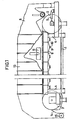
- Fig. 1 shows an arrangement for the liquid treatment of pulp
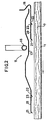
- Fig. 2 is a cross-section through a device for the supply of treatment liquid.
- the embodiment shown comprises an endless belt 1, which runs about a first and a second end roll 2 and, respectively, 3.
- the rolls are arranged in a stand 4 in such a manner, that the first roll 2 is movable by means of a stretching device 5, preferably a hydraulic one, for adjusting the belt tension.
- the driving is effected by the second roll 3.
- a head box 6 is located for distributing the cellulose pulp to a uniform layer 7 on the belt 1.
- a plurality of containers 8 are arranged one after the other in the longitudinal direction of the belt.
- the containers are provided with perforated covers in support of the belt 1.
- Outlets 9 and, respectively, 10 are connected to the containers 8 for the discharge of liquid and, respectively, vapours and gases.
- the liquid outlet is located in the bottom of the container 8 to ensure effective drainage.
- the liquid level in the containers is controlled by special means, so that a little space for vapours and gases is maintained in the upper part. Thereby the drop of the liquid from the belt 1 down into the containers is small and thereby the foaming tendency is reduced.
- a pressure difference is maintained over the pulp layer 7 in order to effect liquid transport transversely through the pulp layer.
- a hood 13 is provided above the belt.
- a transfer device 14 for the completely treated pulp layer is provided, which device, for example, is a doctor blade. Beneath the doctor blade a conveying screw 15 is located for conveying the pulp to subsequent processing steps.
- Each device 11 for the supply of treatment liquid comprises a feed pipe 16, distribution member 17, deflecting member 18 and application members in the form of a front plate 19 and a rear plate 20.
- the leading edge on each plate is provided with a lip 21, which is angular obliquely down to the belt.
- Both plates 19, 20 are provided with a gap 22. Several gaps may possibly be arranged one after the other in the plates 19, 20. In connection to each gap 22 a guide lip 23 is located.
- the treatment liquid flows through the feed pipe 16 down into the distribution member 17, which should be substantially symmetrical relative to the feed pipe 16.
- the liquid flow is divided by the distribution member 17 into two parts, concurrent and, respectively, counter-current to the running direction of the belt 1.
- the concurrent flow thereafter flows onto the front plate 19 of the application member.
- the counter-current first is turned through 180° by the deflecting member 18 before it flows onto the rear plate 20 of the application member.
- each supply device 11 depends on a great number of factors, such as belt speed, pulp layer thickness, distance between the supply devices, pressure drop over the pulp layer and nature of the treatment liquid as well as of the pulp.
- An arrangement according to the invention renders it possible to use liquid flows up to 13 m3 treatment liquid per ton of treated pulp. This implies flows of up to 10000litre/min at a production of 1000 tons of pulp per twenty-four hours. In certain cases even greater flows can be applied. Due to the fact, that the liquid according to the invention is applied concurrent and divided into partial flows, the conditions for displacing the liquid in the pulp layer are very favourable. This in its turn implies that the treatment efficiency and production can be increased by at least 10% compared with conventional technique.
- the size of the gaps 22 can be adjusted and should be in the range 10-20 mm.
- the lips 21 and guide lips 23 should form an angle with the plates 19, 20 of the application member, which angle should be 25-45°, preferably 30-40°.
- the guide lips 23 should be located in the downstream edge of the gaps 22 and be formed so that the edge formed with the plates 19 and, respectively, 20 is sharp.
- the distance between the plates 19, 20 of the application member and the pulp layer should be minimized and preferably be smaller than 50 mm.
Landscapes
- Chemical & Material Sciences (AREA)
- Chemical Kinetics & Catalysis (AREA)
- Life Sciences & Earth Sciences (AREA)
- Engineering & Computer Science (AREA)
- Wood Science & Technology (AREA)
- Paper (AREA)
- Electrical Discharge Machining, Electrochemical Machining, And Combined Machining (AREA)
- Filtration Of Liquid (AREA)
- Extraction Or Liquid Replacement (AREA)
- Steroid Compounds (AREA)
Abstract
Description
- This invention relates to an arrangement for the liquid treatment of pulp, which arrangement comprises a stand with two end rolls, over which an endless liquid pervious belt runs. The belt is a wire or a perforated belt, for example a steel belt. The belt is driven by one of the end rolls and slides over perforated covers on containers located therebeneath. A head box for the supply of pulp is located at one end of the belt, at the other end of which means for transferring the treated pulp are provided. Devices for the supply of treatment liquid to the pulp are located above the belt. The containers located beneath are intended for collecting liquid.
- The devices for the supply of treatment liquid and also the containers extend in the transverse direction across the entire belt width, which can amount to 6 m and in certain cases can be still wider.
- The supply of treatment liquid is effected by a plurality of devices located some distance above the belt. Each supply device normally sprays the liquid both rearward and forward in the running direction of the belt. This type of equipment is shown in WO-A1-85/02424 according to which there are means 11 for supply of treatment liquid. Each of these means comprises a feed pipe and a distribution member for applying the liquid onto the pulp layer while dividing the liquid flow into two parts, concurrent with and counter-current to the running direction of the web. In order to make maximum use of the liquid flow, half of it is directed in either direction. This implies, however, that the liquid applied counter-current has a tendency of mixing with the liquid content of the pulp (the impulse against the pulp web is great) instead of displacing the same.
- The same kind of problem occurs in the device shown in US-A-2185868, which discloses a machine for filtering fluid-suspended solid matter. In this machine wash water is supplied by pipes 78 and sprayed onto the suspension by nozzles 79, both concurrent with and counter-current to the direction of a running filtering belt 7.
- The above mentioned tendency of mixing exists also at concurrent application when the flow is too great. It is desired, however, to apply with each distribution device the maximum amount of liquid. Due to the aforesaid problems, the supply of treatment liquid must be restricted, which at the same time implies a restriction of the production.
- The present invention has the object to solve this problem.
- According to the invention, a softer and more efficient application of the treatment liquid is obtained, which implies that the production can be increased by at least 10% compared with a conventional arrangement for the liquid treatment of pulp. The characterizing features of the invention are apparent from the attached claims.
- The invention is described in greater detail in the following, with reference to the accompanying drawings showing one embodiment of the invention. Fig. 1 shows an arrangement for the liquid treatment of pulp, and Fig. 2 is a cross-section through a device for the supply of treatment liquid.
- The embodiment shown comprises an endless belt 1, which runs about a first and a second end roll 2 and, respectively, 3. The rolls are arranged in a stand 4 in such a manner, that the first roll 2 is movable by means of a
stretching device 5, preferably a hydraulic one, for adjusting the belt tension. The driving is effected by the second roll 3. - At the first roll 2 a
head box 6 is located for distributing the cellulose pulp to a uniform layer 7 on the belt 1. After the head box a plurality ofcontainers 8 are arranged one after the other in the longitudinal direction of the belt. The containers are provided with perforated covers in support of the belt 1.Outlets 9 and, respectively, 10 are connected to thecontainers 8 for the discharge of liquid and, respectively, vapours and gases. The liquid outlet is located in the bottom of thecontainer 8 to ensure effective drainage. The liquid level in the containers is controlled by special means, so that a little space for vapours and gases is maintained in the upper part. Thereby the drop of the liquid from the belt 1 down into the containers is small and thereby the foaming tendency is reduced. - Above the
belt devices 11 for the supply of treatment liquid are located. A pressure difference is maintained over the pulp layer 7 in order to effect liquid transport transversely through the pulp layer. Ahood 13 is provided above the belt. - At the second roll 3 a
transfer device 14 for the completely treated pulp layer is provided, which device, for example, is a doctor blade. Beneath the doctor blade a conveyingscrew 15 is located for conveying the pulp to subsequent processing steps. - Each
device 11 for the supply of treatment liquid comprises afeed pipe 16,distribution member 17, deflectingmember 18 and application members in the form of afront plate 19 and arear plate 20. The leading edge on each plate is provided with alip 21, which is angular obliquely down to the belt. Bothplates gap 22. Several gaps may possibly be arranged one after the other in theplates guide lip 23 is located. - The treatment liquid flows through the
feed pipe 16 down into thedistribution member 17, which should be substantially symmetrical relative to thefeed pipe 16. The liquid flow is divided by thedistribution member 17 into two parts, concurrent and, respectively, counter-current to the running direction of the belt 1. The concurrent flow thereafter flows onto thefront plate 19 of the application member. The counter-current first is turned through 180° by the deflectingmember 18 before it flows onto therear plate 20 of the application member. - From the liquid flow to each
plate 19, 20 a portion is separated through thegap 22 and by means of theguide lip 23 directed obliquely down to the pulp layer 7 on the belt 1. The remaining liquid flow is applied over thelip 21 located at the end of theplates - The liquid flow passing through each
supply device 11, of course, depends on a great number of factors, such as belt speed, pulp layer thickness, distance between the supply devices, pressure drop over the pulp layer and nature of the treatment liquid as well as of the pulp. An arrangement according to the invention renders it possible to use liquid flows up to 13 m³ treatment liquid per ton of treated pulp. This implies flows of up to 10000litre/min at a production of 1000 tons of pulp per twenty-four hours. In certain cases even greater flows can be applied. Due to the fact, that the liquid according to the invention is applied concurrent and divided into partial flows, the conditions for displacing the liquid in the pulp layer are very favourable. This in its turn implies that the treatment efficiency and production can be increased by at least 10% compared with conventional technique. - The size of the
gaps 22 can be adjusted and should be in the range 10-20 mm. Thelips 21 andguide lips 23 should form an angle with theplates guide lips 23 should be located in the downstream edge of thegaps 22 and be formed so that the edge formed with theplates 19 and, respectively, 20 is sharp. The distance between theplates
Claims (7)
Priority Applications (1)
| Application Number | Priority Date | Filing Date | Title |
|---|---|---|---|
| AT87903455T ATE66976T1 (en) | 1986-05-13 | 1987-04-15 | ARRANGEMENT FOR THE LIQUID TREATMENT OF PULP. |
Applications Claiming Priority (2)
| Application Number | Priority Date | Filing Date | Title |
|---|---|---|---|
| SE8602150 | 1986-05-13 | ||
| SE8602150A SE448890B (en) | 1986-05-13 | 1986-05-13 | DEVICE FOR THE SUPPLY OF LIQUID IN TREATMENT OF PASS ON AN ENDLESS, CURRENT RANGE |
Publications (2)
| Publication Number | Publication Date |
|---|---|
| EP0305394A1 EP0305394A1 (en) | 1989-03-08 |
| EP0305394B1 true EP0305394B1 (en) | 1991-09-04 |
Family
ID=20364497
Family Applications (1)
| Application Number | Title | Priority Date | Filing Date |
|---|---|---|---|
| EP87903455A Expired - Lifetime EP0305394B1 (en) | 1986-05-13 | 1987-04-15 | Arrangement for liquid treatment of pulp |
Country Status (12)
| Country | Link |
|---|---|
| US (1) | US4900400A (en) |
| EP (1) | EP0305394B1 (en) |
| JP (1) | JPH07109071B2 (en) |
| AT (1) | ATE66976T1 (en) |
| AU (1) | AU596190B2 (en) |
| CA (1) | CA1275593C (en) |
| DE (2) | DE3772768D1 (en) |
| FI (1) | FI89387C (en) |
| NO (1) | NO166804C (en) |
| NZ (1) | NZ220108A (en) |
| SE (1) | SE448890B (en) |
| WO (1) | WO1987006962A1 (en) |
Families Citing this family (1)
| Publication number | Priority date | Publication date | Assignee | Title |
|---|---|---|---|---|
| AT394737B (en) * | 1989-07-03 | 1992-06-10 | Andritz Ag Maschf | METHOD AND DEVICE FOR THE TREATMENT, IN PARTICULAR LAUNDRY, OF FIBER FUEL-LIQUID MIXTURES |
Family Cites Families (6)
| Publication number | Priority date | Publication date | Assignee | Title |
|---|---|---|---|---|
| US2185868A (en) * | 1937-12-15 | 1940-01-02 | Curt C Schaefer | Filtering machine |
| CH236124A (en) * | 1941-12-06 | 1945-01-15 | Siemens Planiawerke Ag | Method for connecting continuously operating carbon electrodes for electric furnaces. |
| FR2418012A1 (en) * | 1978-02-22 | 1979-09-21 | Rhone Poulenc Ind | METHOD AND DEVICE FOR FEEDING AND DISTRIBUTING A PRODUCT TO BE FILTERED ON A HORIZONTAL FILTERING SURFACE |
| FR2540397A1 (en) * | 1983-02-04 | 1984-08-10 | Gaudfrin Guy | BELT FILTER COMPRISING AN AIR SUCTION DEVICE |
| SE452344B (en) * | 1983-12-02 | 1987-11-23 | Sunds Defibrator | DEVICE FOR CELLULOSAMASSA WASHING |
| SE444826B (en) * | 1984-09-17 | 1986-05-12 | Sunds Defibrator | DEVICE FOR LIQUID TREATMENT OF MASS |
-
1986
- 1986-05-13 SE SE8602150A patent/SE448890B/en not_active IP Right Cessation
-
1987
- 1987-04-15 JP JP62503058A patent/JPH07109071B2/en not_active Expired - Lifetime
- 1987-04-15 AU AU74301/87A patent/AU596190B2/en not_active Ceased
- 1987-04-15 US US07/249,569 patent/US4900400A/en not_active Expired - Fee Related
- 1987-04-15 DE DE8787903455T patent/DE3772768D1/en not_active Expired - Fee Related
- 1987-04-15 WO PCT/SE1987/000192 patent/WO1987006962A1/en not_active Ceased
- 1987-04-15 EP EP87903455A patent/EP0305394B1/en not_active Expired - Lifetime
- 1987-04-15 AT AT87903455T patent/ATE66976T1/en not_active IP Right Cessation
- 1987-04-15 DE DE198787903455T patent/DE305394T1/en active Pending
- 1987-04-27 NZ NZ220108A patent/NZ220108A/en unknown
- 1987-05-12 CA CA000536883A patent/CA1275593C/en not_active Expired - Fee Related
-
1988
- 1988-01-12 NO NO880102A patent/NO166804C/en unknown
- 1988-11-11 FI FI885241A patent/FI89387C/en not_active IP Right Cessation
Also Published As
| Publication number | Publication date |
|---|---|
| JPH07109071B2 (en) | 1995-11-22 |
| ATE66976T1 (en) | 1991-09-15 |
| DE305394T1 (en) | 1989-06-22 |
| FI885241L (en) | 1988-11-11 |
| US4900400A (en) | 1990-02-13 |
| EP0305394A1 (en) | 1989-03-08 |
| NO880102L (en) | 1988-01-12 |
| NO880102D0 (en) | 1988-01-12 |
| NO166804B (en) | 1991-05-27 |
| AU7430187A (en) | 1987-12-01 |
| JPH01502597A (en) | 1989-09-07 |
| FI89387C (en) | 1993-09-27 |
| NO166804C (en) | 1991-09-04 |
| WO1987006962A1 (en) | 1987-11-19 |
| CA1275593C (en) | 1990-10-30 |
| NZ220108A (en) | 1988-08-30 |
| AU596190B2 (en) | 1990-04-26 |
| FI885241A0 (en) | 1988-11-11 |
| SE8602150D0 (en) | 1986-05-13 |
| SE448890B (en) | 1987-03-23 |
| DE3772768D1 (en) | 1991-10-10 |
| FI89387B (en) | 1993-06-15 |
Similar Documents
| Publication | Publication Date | Title |
|---|---|---|
| US8434338B2 (en) | Device for cooling a metal strip | |
| EP0899030A3 (en) | Device and method for cooling the working rolls on the outlet side of a roll stand | |
| EP0675984B1 (en) | Apparatus and method of minimizing skip coating on a paper web | |
| EP1237661B1 (en) | Method and device relating to coating a running web | |
| US5286230A (en) | Apparatus for dividing deep-frozen foodstuffs, with recovery of foodstuffs detached during said division | |
| US4900400A (en) | Arrangement for liquid treatment of pulp | |
| JPH0394862A (en) | Apparatus for coating strip-like object with treating liquid | |
| US4116760A (en) | Method and apparatus for removing liquid from a slurry of solid material | |
| US6101738A (en) | Sludge dewatering system and method | |
| US4184846A (en) | Method and apparatus for liquid processing of tubular knitted fabrics | |
| JPH0221868B2 (en) | ||
| AU596172B2 (en) | Apparatus for liquid treatment of pulp | |
| DE4337286A1 (en) | Method and apparatus for descaling and cleaning rolled stock such as slabs, thin slabs, hot strip or roughed strip | |
| DE2324268A1 (en) | AIR BRUSH COATING SYSTEM WITH UPPER LIP CLEANER | |
| SU1315532A1 (en) | Arrangement for treating wet waste of beated bast cultures | |
| JPS647035Y2 (en) | ||
| DE2005857A1 (en) | Improved Apparatus for Making Paper | |
| DE1778038A1 (en) | Device for cutting and removing rubber heads | |
| DE8309902U1 (en) | DEVICE FOR BRAKING AND OVERLAPPING PAPER SHEETS IN PAPER PROCESSING MACHINES | |
| AT508974A2 (en) | APPARATUS AND METHOD FOR TREATING A FIBERWORK | |
| DE29921800U1 (en) | Spray station | |
| DE1522872B (en) | Film processor |
Legal Events
| Date | Code | Title | Description |
|---|---|---|---|
| PUAI | Public reference made under article 153(3) epc to a published international application that has entered the european phase |
Free format text: ORIGINAL CODE: 0009012 |
|
| 17P | Request for examination filed |
Effective date: 19880912 |
|
| AK | Designated contracting states |
Kind code of ref document: A1 Designated state(s): AT DE FR GB SE |
|
| EL | Fr: translation of claims filed | ||
| TCAT | At: translation of patent claims filed | ||
| DET | De: translation of patent claims | ||
| RAP1 | Party data changed (applicant data changed or rights of an application transferred) |
Owner name: SUNDS DEFIBRATOR INDUSTRIES AKTIENBOLAG |
|
| RAP3 | Party data changed (applicant data changed or rights of an application transferred) |
Owner name: SUNDS DEFIBRATOR INDUSTRIES AKTIEBOLAG |
|
| 17Q | First examination report despatched |
Effective date: 19900723 |
|
| GRAA | (expected) grant |
Free format text: ORIGINAL CODE: 0009210 |
|
| AK | Designated contracting states |
Kind code of ref document: B1 Designated state(s): AT DE FR GB SE |
|
| PG25 | Lapsed in a contracting state [announced via postgrant information from national office to epo] |
Ref country code: SE Effective date: 19910904 |
|
| REF | Corresponds to: |
Ref document number: 66976 Country of ref document: AT Date of ref document: 19910915 Kind code of ref document: T |
|
| ET | Fr: translation filed | ||
| REF | Corresponds to: |
Ref document number: 3772768 Country of ref document: DE Date of ref document: 19911010 |
|
| PG25 | Lapsed in a contracting state [announced via postgrant information from national office to epo] |
Ref country code: GB Effective date: 19920415 |
|
| PLBE | No opposition filed within time limit |
Free format text: ORIGINAL CODE: 0009261 |
|
| STAA | Information on the status of an ep patent application or granted ep patent |
Free format text: STATUS: NO OPPOSITION FILED WITHIN TIME LIMIT |
|
| 26N | No opposition filed | ||
| GBPC | Gb: european patent ceased through non-payment of renewal fee | ||
| PGFP | Annual fee paid to national office [announced via postgrant information from national office to epo] |
Ref country code: AT Payment date: 19980415 Year of fee payment: 12 |
|
| PGFP | Annual fee paid to national office [announced via postgrant information from national office to epo] |
Ref country code: DE Payment date: 19980417 Year of fee payment: 12 |
|
| PGFP | Annual fee paid to national office [announced via postgrant information from national office to epo] |
Ref country code: FR Payment date: 19980420 Year of fee payment: 12 |
|
| PG25 | Lapsed in a contracting state [announced via postgrant information from national office to epo] |
Ref country code: AT Free format text: LAPSE BECAUSE OF NON-PAYMENT OF DUE FEES Effective date: 19990415 |
|
| PG25 | Lapsed in a contracting state [announced via postgrant information from national office to epo] |
Ref country code: FR Free format text: LAPSE BECAUSE OF NON-PAYMENT OF DUE FEES Effective date: 19991231 |
|
| REG | Reference to a national code |
Ref country code: FR Ref legal event code: ST |
|
| PG25 | Lapsed in a contracting state [announced via postgrant information from national office to epo] |
Ref country code: DE Free format text: LAPSE BECAUSE OF NON-PAYMENT OF DUE FEES Effective date: 20000201 |