EP0305061B1 - Verfahren zum Formen verstärkter Kastenrahmen - Google Patents
Verfahren zum Formen verstärkter Kastenrahmen Download PDFInfo
- Publication number
- EP0305061B1 EP0305061B1 EP88307073A EP88307073A EP0305061B1 EP 0305061 B1 EP0305061 B1 EP 0305061B1 EP 88307073 A EP88307073 A EP 88307073A EP 88307073 A EP88307073 A EP 88307073A EP 0305061 B1 EP0305061 B1 EP 0305061B1
- Authority
- EP
- European Patent Office
- Prior art keywords
- tube
- sleeve
- die
- section
- cross
- Prior art date
- Legal status (The legal status is an assumption and is not a legal conclusion. Google has not performed a legal analysis and makes no representation as to the accuracy of the status listed.)
- Expired - Lifetime
Links
- 238000000034 method Methods 0.000 title claims description 33
- 238000005452 bending Methods 0.000 claims description 12
- 239000012530 fluid Substances 0.000 claims description 10
- 230000008569 process Effects 0.000 claims description 6
- 230000013011 mating Effects 0.000 claims 1
- 230000002787 reinforcement Effects 0.000 abstract description 2
- 239000000463 material Substances 0.000 description 6
- 239000000047 product Substances 0.000 description 6
- 239000012467 final product Substances 0.000 description 5
- 230000006872 improvement Effects 0.000 description 3
- 230000003014 reinforcing effect Effects 0.000 description 3
- 229910000831 Steel Inorganic materials 0.000 description 2
- 230000015572 biosynthetic process Effects 0.000 description 2
- 230000000295 complement effect Effects 0.000 description 2
- 239000007788 liquid Substances 0.000 description 2
- 238000004519 manufacturing process Methods 0.000 description 2
- 239000002184 metal Substances 0.000 description 2
- 230000009467 reduction Effects 0.000 description 2
- 239000010959 steel Substances 0.000 description 2
- 230000008901 benefit Effects 0.000 description 1
- 230000006835 compression Effects 0.000 description 1
- 238000007906 compression Methods 0.000 description 1
- 239000000203 mixture Substances 0.000 description 1
- 238000012986 modification Methods 0.000 description 1
- 230000004048 modification Effects 0.000 description 1
- 238000007789 sealing Methods 0.000 description 1
- 239000007858 starting material Substances 0.000 description 1
Images
Classifications
-
- B—PERFORMING OPERATIONS; TRANSPORTING
- B30—PRESSES
- B30B—PRESSES IN GENERAL
- B30B1/00—Presses, using a press ram, characterised by the features of the drive therefor, pressure being transmitted directly, or through simple thrust or tension members only, to the press ram or platen
- B30B1/32—Presses, using a press ram, characterised by the features of the drive therefor, pressure being transmitted directly, or through simple thrust or tension members only, to the press ram or platen by plungers under fluid pressure
-
- B—PERFORMING OPERATIONS; TRANSPORTING
- B21—MECHANICAL METAL-WORKING WITHOUT ESSENTIALLY REMOVING MATERIAL; PUNCHING METAL
- B21D—WORKING OR PROCESSING OF SHEET METAL OR METAL TUBES, RODS OR PROFILES WITHOUT ESSENTIALLY REMOVING MATERIAL; PUNCHING METAL
- B21D26/00—Shaping without cutting otherwise than using rigid devices or tools or yieldable or resilient pads, i.e. applying fluid pressure or magnetic forces
- B21D26/02—Shaping without cutting otherwise than using rigid devices or tools or yieldable or resilient pads, i.e. applying fluid pressure or magnetic forces by applying fluid pressure
- B21D26/033—Deforming tubular bodies
- B21D26/051—Deforming double-walled bodies
-
- B—PERFORMING OPERATIONS; TRANSPORTING
- B21—MECHANICAL METAL-WORKING WITHOUT ESSENTIALLY REMOVING MATERIAL; PUNCHING METAL
- B21D—WORKING OR PROCESSING OF SHEET METAL OR METAL TUBES, RODS OR PROFILES WITHOUT ESSENTIALLY REMOVING MATERIAL; PUNCHING METAL
- B21D11/00—Bending not restricted to forms of material mentioned in only one of groups B21D5/00, B21D7/00, B21D9/00; Bending not provided for in groups B21D5/00 - B21D9/00; Twisting
- B21D11/10—Bending specially adapted to produce specific articles, e.g. leaf springs
-
- B—PERFORMING OPERATIONS; TRANSPORTING
- B21—MECHANICAL METAL-WORKING WITHOUT ESSENTIALLY REMOVING MATERIAL; PUNCHING METAL
- B21D—WORKING OR PROCESSING OF SHEET METAL OR METAL TUBES, RODS OR PROFILES WITHOUT ESSENTIALLY REMOVING MATERIAL; PUNCHING METAL
- B21D11/00—Bending not restricted to forms of material mentioned in only one of groups B21D5/00, B21D7/00, B21D9/00; Bending not provided for in groups B21D5/00 - B21D9/00; Twisting
- B21D11/18—Joggling
-
- Y—GENERAL TAGGING OF NEW TECHNOLOGICAL DEVELOPMENTS; GENERAL TAGGING OF CROSS-SECTIONAL TECHNOLOGIES SPANNING OVER SEVERAL SECTIONS OF THE IPC; TECHNICAL SUBJECTS COVERED BY FORMER USPC CROSS-REFERENCE ART COLLECTIONS [XRACs] AND DIGESTS
- Y10—TECHNICAL SUBJECTS COVERED BY FORMER USPC
- Y10T—TECHNICAL SUBJECTS COVERED BY FORMER US CLASSIFICATION
- Y10T29/00—Metal working
- Y10T29/49—Method of mechanical manufacture
- Y10T29/49616—Structural member making
- Y10T29/49623—Static structure, e.g., a building component
- Y10T29/49625—Openwork, e.g., a truss, joist, frame, lattice-type or box beam
- Y10T29/49627—Frame component
-
- Y—GENERAL TAGGING OF NEW TECHNOLOGICAL DEVELOPMENTS; GENERAL TAGGING OF CROSS-SECTIONAL TECHNOLOGIES SPANNING OVER SEVERAL SECTIONS OF THE IPC; TECHNICAL SUBJECTS COVERED BY FORMER USPC CROSS-REFERENCE ART COLLECTIONS [XRACs] AND DIGESTS
- Y10—TECHNICAL SUBJECTS COVERED BY FORMER USPC
- Y10T—TECHNICAL SUBJECTS COVERED BY FORMER US CLASSIFICATION
- Y10T29/00—Metal working
- Y10T29/49—Method of mechanical manufacture
- Y10T29/49826—Assembling or joining
- Y10T29/49861—Sizing mating parts during final positional association
-
- Y—GENERAL TAGGING OF NEW TECHNOLOGICAL DEVELOPMENTS; GENERAL TAGGING OF CROSS-SECTIONAL TECHNOLOGIES SPANNING OVER SEVERAL SECTIONS OF THE IPC; TECHNICAL SUBJECTS COVERED BY FORMER USPC CROSS-REFERENCE ART COLLECTIONS [XRACs] AND DIGESTS
- Y10—TECHNICAL SUBJECTS COVERED BY FORMER USPC
- Y10T—TECHNICAL SUBJECTS COVERED BY FORMER US CLASSIFICATION
- Y10T29/00—Metal working
- Y10T29/49—Method of mechanical manufacture
- Y10T29/49826—Assembling or joining
- Y10T29/49908—Joining by deforming
- Y10T29/49925—Inward deformation of aperture or hollow body wall
- Y10T29/49927—Hollow body is axially joined cup or tube
-
- Y—GENERAL TAGGING OF NEW TECHNOLOGICAL DEVELOPMENTS; GENERAL TAGGING OF CROSS-SECTIONAL TECHNOLOGIES SPANNING OVER SEVERAL SECTIONS OF THE IPC; TECHNICAL SUBJECTS COVERED BY FORMER USPC CROSS-REFERENCE ART COLLECTIONS [XRACs] AND DIGESTS
- Y10—TECHNICAL SUBJECTS COVERED BY FORMER USPC
- Y10T—TECHNICAL SUBJECTS COVERED BY FORMER US CLASSIFICATION
- Y10T29/00—Metal working
- Y10T29/49—Method of mechanical manufacture
- Y10T29/49826—Assembling or joining
- Y10T29/49908—Joining by deforming
- Y10T29/49938—Radially expanding part in cavity, aperture, or hollow body
- Y10T29/4994—Radially expanding internal tube
Definitions
- This invention relates to a method of forming hollow, box-section, frame members which include localized reinforcement.
- a tubular blank is first bent into a required curved shape. Then, the curved blank is placed in a preforming die to deform the sidewalls of the blank. The sidewalls are then inwardly recessed and concavely curved in areas corresponding to the areas that will form proposed planar sidewalls in the final frame member.
- This allows the deformed blank to be placed in a final die, which has a cavity corresponding to the desired cross-sectional shape of the final frame member, and the die to be closed without pinching the wall of the blank.
- the blank is then expanded by an internal fluid pressure which exceeds the yield limit of its sidewall. The sidewall thus expands outwardly to conform to the interior of the final die cavity.
- the method thus provides a convenient method of forming hollow, box-section, frame members.
- This invention provides a method of forming a box-section frame member which has a reinforced area and of which at least an elongate portion is of uniform cross-section having at least two generally opposed and planar sides, the method comprising: providing a tube and a tubular sleeve within which the tube can be received, the tube and sleeve each having a similar continuously smooth, arcuate cross-section; positioning the sleeve about the tube in an area of the tube to be reinforced; deforming the tube and sleeve in a preliminary step in which the sidewalls thereof are deformed inwardly in opposed areas of an elongate portion thereof which corresponds in position to where planar sides of the product frame member are subsquently to be produced to provide the tube and sleeve with a continuously smooth arcuate cross-section having generally opposed, inwardly deformed, side walls; enclosing the deformed tube and sleeve within a sectional die having at least two co-operating die sections which define an elongate
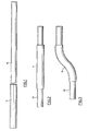
- a cylindrical tube 10 and a cylindrical sleeve 11 are illustrated.
- the inner diameter of the sleeve is such that the cylindrical tube 10 may be slid easily into the sleeve.
- the outer diameter of the cylindrical tube 10 is preferably only just smaller than the inner diameter of the cylindrical sleeve 11. Therefore, the tube 10 need not be expanded greatly before its outer surface matches the outer surface of the sleeve.
- Figure 2 illustrates the tube 10 inserted within the sleeve 11.
- the assembled sleeve 11 and the tube 10 of Figure 2 may be bent along their lengths to obtain a desired shape.
- the tube 10 and the sleeve 11 are bent into approximately an "S" configuration with the bends being in the region of the sleeve.
- the shape of the bend is the shape desired in the product frame member.
- the bending operation may be performed by using conventional bending procedures, for example mandrel bending, or stretch bending. These bending procedures are generally well known in the art and will not be described in detail in this specification. However, in essence, in mandrel bending an internal mandrel is used while in stretch bending no internal mandrel is used.
- the minimum radius of the bend that may be imparted to a cylindrical tube is approximately twice the diameter of the tube. Also, the minimum distance between adjacent bent portions is approximately one tube diameter. Further more, a cross-sectional area reduction of about 5% is usually achieved. In stretch bending, a minimum bend radius is approximately three times the diameter of the tube, while the minimum distance between adjacent bends will be approximately one-half of the diameter of the tube. Usually, a cross-sectional area reduction of about 15% is achieved.
- the sleeve 11 and the tube 10 are bent at the same time and while the sleeve covers the portion of the tube to be bent, in the event that the portion to be reinforced is desired to be curved.
- the bent tube and sleeve of Figure 3 are then subjected to a preliminary process to prevent pinching thereof in a final die.
- This may be achieved by preforming or by internally pressurizing the tube.
- a suitable preforming die is well described in the above-mentioned EP-A-0195157 and will not be described in detail in this specification.
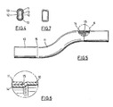
- the die consists of two metal halves each having a recess formed into a surface thereof.
- the recess is in the form of an elongated channel which may extend the length of the half.
- the recesses complement one another to form an elongated tubular passage. This passage is approximately hourglass shaped in cross-section.
- the tube and sleeve maintain a smoothly continuous and gently rounded cross-sectional profile during all steps in the forming process. It has been found that this inhibits formation of points of stress when expanded in the subsequent final die. This facilitates the production of a box-section frame member with good mechanical strength.
- the tube and sleeve may be subjected to expansion in the final die.
- This procedure and the die in which the procedure takes place is well described in the above-mentioned EP-A-0195157.
- the die consists of upper and lower halves each having a recess formed into one side thereof.
- the recesses complement one another to form an elongated passage of substantially rectangular cross-section.
- the corners of the rectangle are smoothly curved.
- the elongated passage may be curved in its length so as to correspond to the desired curves of the frame member. The ends of the tube located within the passage are then sealed.
- a liquid hydraulic fluid is then injected through one of the seals to internally pressurize the tube and sleeve.
- the internal pressure is sufficient to expand the sidewall of the tube, and to expand or to outwardly deform the sidewall of the sleeve, evenly into conformity with the substantially rectangularly-shaped passage.
- the product frame member has a cross-sectional shape substantially as illustrated in Figure 7.
- the pressure is sufficient to exceed the yield limit of the sidewall of the tube and, if necessary, of the sleeve. This pressure depends on the thickness of the sidewall of the material being expanded as well as on its nature or composition. However, the pressure may be in the region of 20,000 kPa (3,000 psi).
- the upper and lower halves of the die are held together with sufficient force to prevent any movement during expansion of the tube. This expansion procedure produces a box-section frame having localized reinforcing to a very high degree of accuracy, uniformity, and repeatability.
- the tube may be pre-pressurized by sealing the ends of the tube and injecting liquid hydraulic fluid through one of the seals into the tube.
- This method is better described in the above-mentioned EP-A-0294034.
- the internal fluid pressurizes the tube to a pressure below the yield limit of the sidewall of the blank or tube.
- the pressure is selected so that, on closing of the two halves of the final die, it is sufficient to overcome frictional drag exerted by the die halves on the sleeve and on the tube. It is convenient to lay the tube and sleeve within the recess of one die half, internally pressurize the tube, and then close the other die half on to the first die half.
- the tube and sleeve On closing of the die halves, the tube and sleeve are inwardly deformed as their upper and lower sides engage the surfaces of the die recesses. This compression urges the lateral sides of the tube and sleeve laterally outward to a point where a lateral portion of the tube and sleeve engages the sides of the die passage. This engagement occurs almost simultaneously with the closing of the two die halves on to each other. Therefore, pinching of the tube and sleeve between the two die halves does not occur.
- the internal pressure required to prevent pinching of the tube and sleeve within the die may be readily determined by trial and experiment for given dimensions and configurations. Typically, the pressure will be approximately 2,000 kPa (300 psi).
- the upper and lower sidewalls of the tube and sleeve are deformed inwardly but the tube and sleeve both maintain a continuously smooth arcuate cross-section.
- the tube and sleeve may then be fully expanded to form a reinforced, box-section frame member as described above.
- One advantage of this improvement is that only a single die is required for both preforming and final expanding.
- the pressure is released, and the hydraulic fluid is pumped out of the interior of the deformed tube.
- the upper and lower halves of the die are then separated and the final product is removed from the die.
- the box-section frame member produced by this process has a substantially continuous, uniform, outer surface although a small discontinuity 15 occurs in the surface at both ends of the sleeve 11.
- the tube 10 includes an area 14 which is inwardly offset the thickness of the sleeve over a length approximately the same as the length of the sleeve 11. The offset portion receives and engages the ends of the sleeve 11 and securely locks the sleeve 11 to the tube 10. Therefore, the final product is a locally reinforced box-section frame member which is substantially continuous and uniform in its outer surface and is mechanically sound.
- the starting material tube preferably is selected so that the circumference of the final product frame member is at no point along its length more than 5% larger than the circumference of the starting tube. At least with the readily available grades of tubular steel, if the tube is expanded in circumference by more than about 5%, there is a tendency for the material of the sidewall of the tube or sleeve to excessively weaken or to crack. Expansions of the tube circumference of up to about 20% may be performed if the material of the tube is fully annealed, however it is preferable to use metal which has not been pretreated in this manner.
- the sleeve 11 may be of the same circumference or less than the circumference of the final product.
- the sleeve 11 may be, for example, of the same material as the tube 10, e.g. SAE 1010 steel, or may be, for example, any material which is sufficiently ductile that it may be expanded to a circumference which is 5-10% larger than its original circumference.
- the tensile properties of the sleeve material may be, for example, lower or up to 30% greater than that of the tube as the expansion required to lock the sleeve to the tube may be performed on the tube without expansion of the sleeve itself.
- the starting tube and sleeve may be of elliptical cross-section rather than circular cross-section; the tube and sleeve may be bent into a curved shape after they have been formed into a box-section frame member; and the cross-sectional shape of the box-section frame member may be trapezoidal, hexagonal or of any suitable polygon cross-section.
Landscapes
- Engineering & Computer Science (AREA)
- Mechanical Engineering (AREA)
- Physics & Mathematics (AREA)
- Fluid Mechanics (AREA)
- Shaping Metal By Deep-Drawing, Or The Like (AREA)
- Bridges Or Land Bridges (AREA)
- Superconductors And Manufacturing Methods Therefor (AREA)
- Making Paper Articles (AREA)
- Patch Boards (AREA)
- Sealing Battery Cases Or Jackets (AREA)
- Bending Of Plates, Rods, And Pipes (AREA)
Claims (8)
Priority Applications (1)
| Application Number | Priority Date | Filing Date | Title |
|---|---|---|---|
| AT88307073T ATE69747T1 (de) | 1987-08-27 | 1988-08-01 | Verfahren zum formen verstaerkter kastenrahmen. |
Applications Claiming Priority (2)
| Application Number | Priority Date | Filing Date | Title |
|---|---|---|---|
| US07/090,952 US4759111A (en) | 1987-08-27 | 1987-08-27 | Method of forming reinforced box-selection frame members |
| US90952 | 1987-08-27 |
Publications (3)
| Publication Number | Publication Date |
|---|---|
| EP0305061A2 EP0305061A2 (de) | 1989-03-01 |
| EP0305061A3 EP0305061A3 (en) | 1989-09-06 |
| EP0305061B1 true EP0305061B1 (de) | 1991-11-27 |
Family
ID=22225100
Family Applications (1)
| Application Number | Title | Priority Date | Filing Date |
|---|---|---|---|
| EP88307073A Expired - Lifetime EP0305061B1 (de) | 1987-08-27 | 1988-08-01 | Verfahren zum Formen verstärkter Kastenrahmen |
Country Status (11)
| Country | Link |
|---|---|
| US (1) | US4759111A (de) |
| EP (1) | EP0305061B1 (de) |
| JP (1) | JP2701878B2 (de) |
| KR (1) | KR970010546B1 (de) |
| AT (1) | ATE69747T1 (de) |
| BR (1) | BR8803883A (de) |
| CA (1) | CA1314133C (de) |
| DE (1) | DE3866474D1 (de) |
| ES (1) | ES2028284T3 (de) |
| GR (1) | GR3003382T3 (de) |
| MX (1) | MX163447B (de) |
Families Citing this family (51)
| Publication number | Priority date | Publication date | Assignee | Title |
|---|---|---|---|---|
| US5890387A (en) * | 1989-08-24 | 1999-04-06 | Aquaform Inc. | Apparatus and method for forming and hydropiercing a tubular frame member |
| US5481892A (en) * | 1989-08-24 | 1996-01-09 | Roper; Ralph E. | Apparatus and method for forming a tubular member |
| CA2023675C (en) * | 1989-08-24 | 2001-07-31 | Ralph E. Roper | Apparatus and method for forming a tubular frame member |
| US5353618A (en) | 1989-08-24 | 1994-10-11 | Armco Steel Company, L.P. | Apparatus and method for forming a tubular frame member |
| US5070717A (en) * | 1991-01-22 | 1991-12-10 | General Motors Corporation | Method of forming a tubular member with flange |
| US5170557A (en) * | 1991-05-01 | 1992-12-15 | Benteler Industries, Inc. | Method of forming a double wall, air gap exhaust duct component |
| US5333775A (en) * | 1993-04-16 | 1994-08-02 | General Motors Corporation | Hydroforming of compound tubes |
| US5363544A (en) * | 1993-05-20 | 1994-11-15 | Benteler Industries, Inc. | Multi-stage dual wall hydroforming |
| US5564785A (en) * | 1994-10-17 | 1996-10-15 | Atoma International Inc. | Seat frame assembly for a motor vehicle |
| US5641176A (en) * | 1995-03-31 | 1997-06-24 | Mascotech Tubular Products, Inc. | Process of hydroforming tubular suspension and frame components for vehicles |
| US5765285A (en) * | 1995-08-09 | 1998-06-16 | The B.F. Goodrich Company | Method of bending a rigid thermoplastic pipe |
| US5557961A (en) * | 1995-11-13 | 1996-09-24 | General Motors Corporation | Hydroformed structural member with varied wall thickness |
| US5720092A (en) * | 1996-08-21 | 1998-02-24 | General Motors Corporation | Method for hydroforming a vehicle space frame |
| US6006567A (en) * | 1997-05-15 | 1999-12-28 | Aquaform Inc | Apparatus and method for hydroforming |
| US6502822B1 (en) | 1997-05-15 | 2003-01-07 | Aquaform, Inc. | Apparatus and method for creating a seal on an inner wall of a tube for hydroforming |
| GB9721465D0 (en) * | 1997-10-10 | 1997-12-10 | Gkn Sankey Ltd | A process for producing a tubular structural element |
| US6623067B2 (en) | 1997-10-16 | 2003-09-23 | Magna International Inc. | Door seal interface structure for a motor vehicle space frame |
| US6621037B2 (en) | 1997-10-16 | 2003-09-16 | Magna International Inc. | Welding material with conductive sheet and method |
| US6533348B1 (en) | 1997-10-16 | 2003-03-18 | Cosma International Inc. | Modular space frame |
| US6689982B2 (en) | 1997-10-16 | 2004-02-10 | Magna International, Inc. | Apparatus and method for welding aluminum tubes |
| US6302478B1 (en) | 1997-10-16 | 2001-10-16 | Cosma International Inc. | Hydroformed space frame joints therefor |
| US6713707B2 (en) | 1997-10-16 | 2004-03-30 | Magna International, Inc. | Welding material and method without carrier |
| US6346684B1 (en) | 1997-10-16 | 2002-02-12 | Cosma International Inc. | Welding material assembly and method |
| EA001477B1 (ru) * | 1997-10-16 | 2001-04-23 | Косма Интернэшнл Инк. | Пространственная рама для автомобиля и способ ее изготовления (варианты) |
| US6216509B1 (en) | 1998-08-25 | 2001-04-17 | R.J. Tower Corporation | Hydroformed tubular member and method of hydroforming tubular members |
| DE19851492A1 (de) * | 1998-11-09 | 2000-05-11 | Volkswagen Ag | Verfahren zum Herstellen eines Bauteils mittels Innenhochdruck-Umformen |
| US6519855B1 (en) | 1999-08-31 | 2003-02-18 | Dana Corporation | Method of manufacturing a vehicle body and frame assembly |
| US6412818B1 (en) | 1999-08-31 | 2002-07-02 | Dana Corporation | Vehicle body and frame assembly and method of manufacturing same |
| US6609301B1 (en) * | 1999-09-08 | 2003-08-26 | Magna International Inc. | Reinforced hydroformed members and methods of making the same |
| US6566624B2 (en) | 2000-03-03 | 2003-05-20 | Magna International Inc. | Welding assembly with nestable conductive ends |
| JP2001353519A (ja) * | 2000-06-14 | 2001-12-25 | Suncall Corp | 二重構造クラッドパイプ及びその製造方法 |
| US6505389B2 (en) * | 2000-12-19 | 2003-01-14 | F&P Mfg., Inc. | Apparatus and method for forming a tube having an article attached thereto |
| CA2342702A1 (en) * | 2001-04-04 | 2002-10-04 | Copperweld Canada Inc. | Forming method using tube blanks of variable wall thickness |
| JP4207570B2 (ja) | 2001-05-22 | 2009-01-14 | 三菱自動車工業株式会社 | ハイドロフォーム成形方法 |
| US6585331B2 (en) * | 2001-09-06 | 2003-07-01 | Meritor Heavy Vehicle Technology, Llc | Tubular axle beam |
| US6557930B1 (en) * | 2001-10-26 | 2003-05-06 | General Motors Corporation | Multi-section support rail apparatus and method of making |
| US7047615B2 (en) * | 2002-05-06 | 2006-05-23 | Norek Richard S | Forming gas turbine transition duct bodies without longitudinal welds |
| JP2004212794A (ja) * | 2003-01-07 | 2004-07-29 | Konica Minolta Holdings Inc | 医療用カセッテ |
| US20040250404A1 (en) * | 2003-01-14 | 2004-12-16 | Cripsey Timothy J. | Process for press forming metal tubes |
| US6948225B2 (en) * | 2003-01-23 | 2005-09-27 | Arvinmeritor Technology | Hydroformed tubular structure and method of making same |
| US20060096099A1 (en) * | 2003-05-08 | 2006-05-11 | Noble Metal Processing, Inc. | Automotive crush tip and method of manufacturing |
| US6922882B2 (en) * | 2003-05-19 | 2005-08-02 | General Motors Corporation | Method of joining tubular members |
| DE10333678B4 (de) * | 2003-07-24 | 2006-06-08 | Thyssenkrupp Steel Ag | Verfahren zum Herstellen eines abschnittweise verstärkten rohrförmigen Trägers aus Metall, insbesondere für Tragstrukturen in Kraftfahrzeugen |
| US7334312B2 (en) * | 2005-02-23 | 2008-02-26 | U.S. Manufacturing Corporation | Method of forming axles with internally thickened wall sections |
| US20070283562A1 (en) * | 2006-06-05 | 2007-12-13 | Benteler Automotive Corporation | Method for making a non-driving vehicle axle beam |
| US7967308B2 (en) * | 2007-04-06 | 2011-06-28 | Magna International Inc. | Stress reducing inner sleeve for twist beam and associated method |
| JP5136203B2 (ja) * | 2008-05-20 | 2013-02-06 | 京セラドキュメントソリューションズ株式会社 | 画像形成システム |
| US20110233883A1 (en) * | 2010-03-26 | 2011-09-29 | Watson Curtis G | Sulky |
| GB2486224B8 (en) * | 2010-12-07 | 2013-06-19 | Europ Technical Ct Etc Steering Nsk Deutschland Gmbh | Tailored thickness steering tube |
| CN113664064A (zh) * | 2021-08-13 | 2021-11-19 | 山东钢铁集团日照有限公司 | 一种差厚管制管方法 |
| CN121067148A (zh) * | 2025-11-05 | 2025-12-05 | 长城汽车股份有限公司 | 一种变径管件及其制备方法 |
Family Cites Families (12)
| Publication number | Priority date | Publication date | Assignee | Title |
|---|---|---|---|---|
| US610262A (en) * | 1898-09-06 | Tubular bar | ||
| US2044322A (en) * | 1934-06-16 | 1936-06-16 | Murray Corp | Method and means for bending tubing |
| US2102325A (en) * | 1936-06-09 | 1937-12-14 | Boeing Aircraft Co | Airplane control rod and method of making the same |
| US2595695A (en) * | 1947-09-24 | 1952-05-06 | Justrite Manufacturing Co | Tubular aluminum bail with reinforcing inserts at ends |
| US2752179A (en) * | 1951-01-26 | 1956-06-26 | Fuller Brush Co | Tube and socket connection and method of making |
| US2774384A (en) * | 1953-09-15 | 1956-12-18 | Griscom Russell Co | Heat exchanger u-tubes |
| US3009484A (en) * | 1958-09-08 | 1961-11-21 | Arvin Ind Inc | Sound attenuating laminated pipe |
| US3253326A (en) * | 1962-10-11 | 1966-05-31 | Combustion Eng | Method of bending concentrically arranged tubes simultaneously |
| US3550269A (en) * | 1966-03-26 | 1970-12-29 | Furukawa Electric Co Ltd | Method of manufacturing insulated bus bar |
| US3863328A (en) * | 1972-10-10 | 1975-02-04 | Copperweld Steel Co | Method of making a Composite steel tubing |
| DE2822114C2 (de) * | 1977-12-30 | 1982-11-18 | Industria Auxiliar Alavesa, S.A. (Inauxa, S.A.), Amurrio, Alava | Vorrichtung zum Biegen von Kröpfungen in ein Rohr, insbesondere bei der Herstellung einer Kfz-Achse |
| US4567743A (en) * | 1985-03-19 | 1986-02-04 | Standard Tube Canada Inc. | Method of forming box-section frame members |
-
1987
- 1987-08-27 US US07/090,952 patent/US4759111A/en not_active Expired - Lifetime
-
1988
- 1988-07-20 CA CA000572582A patent/CA1314133C/en not_active Expired - Fee Related
- 1988-08-01 AT AT88307073T patent/ATE69747T1/de not_active IP Right Cessation
- 1988-08-01 EP EP88307073A patent/EP0305061B1/de not_active Expired - Lifetime
- 1988-08-01 DE DE8888307073T patent/DE3866474D1/de not_active Expired - Lifetime
- 1988-08-01 ES ES198888307073T patent/ES2028284T3/es not_active Expired - Lifetime
- 1988-08-05 BR BR8803883A patent/BR8803883A/pt not_active IP Right Cessation
- 1988-08-10 MX MX12613A patent/MX163447B/es unknown
- 1988-08-11 KR KR1019880010231A patent/KR970010546B1/ko not_active Expired - Fee Related
- 1988-08-26 JP JP63210900A patent/JP2701878B2/ja not_active Expired - Fee Related
-
1991
- 1991-12-18 GR GR91402070T patent/GR3003382T3/el unknown
Non-Patent Citations (1)
| Title |
|---|
| PATENT ABSTRACT OF JAPAN vol. 8, n° 258, 27th November 1984; & JP - A - 59 130 633 (MASANOBU NAKAMURA) 27-07-1984 * |
Also Published As
| Publication number | Publication date |
|---|---|
| EP0305061A2 (de) | 1989-03-01 |
| JP2701878B2 (ja) | 1998-01-21 |
| BR8803883A (pt) | 1989-03-14 |
| ES2028284T3 (es) | 1992-07-01 |
| CA1314133C (en) | 1993-03-09 |
| ATE69747T1 (de) | 1991-12-15 |
| US4759111A (en) | 1988-07-26 |
| MX163447B (es) | 1992-05-14 |
| KR890003522A (ko) | 1989-04-15 |
| JPH01205833A (ja) | 1989-08-18 |
| DE3866474D1 (de) | 1992-01-09 |
| EP0305061A3 (en) | 1989-09-06 |
| GR3003382T3 (en) | 1993-02-17 |
| KR970010546B1 (ko) | 1997-06-28 |
Similar Documents
| Publication | Publication Date | Title |
|---|---|---|
| EP0305061B1 (de) | Verfahren zum Formen verstärkter Kastenrahmen | |
| EP0294034B1 (de) | Verfahren zum Herstellen kistenförmiger Gegenstände | |
| US4829803A (en) | Method of forming box-like frame members | |
| USRE33990E (en) | Method of forming box-like frame members | |
| CA1227921A (en) | Method for forming box-section frame members | |
| US5070717A (en) | Method of forming a tubular member with flange | |
| EP0693981B1 (de) | Vorrichtung und verfahren zur streckformung von langgestreckten metallhohlprofilen | |
| JP3509217B2 (ja) | 異形断面管の成形方法並びに成形装置 | |
| CN1816402B (zh) | 由平面的金属薄板制造空心型材的方法 | |
| EP1161316B1 (de) | Kompressive innenhochdruckformung | |
| US8141404B2 (en) | Method of manufacturing structural components from tube blanks of variable wall thickness | |
| WO1994022611A9 (en) | Apparatus and method for the stretch forming of elongated hollow metal sections | |
| EP0693980B1 (de) | Flexibele festhaltevorrichtung und verfahren zum streckformen länglicher metallhohlprofile | |
| KR950009143B1 (ko) | 튜브 벤드를 제조하는 방법 | |
| US6766678B1 (en) | Process for deforming a piece of thin-walled metal tube | |
| JP2002153917A (ja) | バルジ加工方法 | |
| US20070169530A1 (en) | Techniques for reducing wall thinning during a hydroforming operation | |
| KR0131464B1 (ko) | 상자형 프레임부재의 성형방법 | |
| SU1189537A1 (ru) | Способ получени рельефа на концах трубных заготовок | |
| SU1480956A1 (ru) | Способ изготовлени полых тонкостенных изделий с многослойным краевым утолщением в виде профильного венца | |
| TH5174B (th) | คลิ๊ปหนีบผม |
Legal Events
| Date | Code | Title | Description |
|---|---|---|---|
| PUAI | Public reference made under article 153(3) epc to a published international application that has entered the european phase |
Free format text: ORIGINAL CODE: 0009012 |
|
| AK | Designated contracting states |
Kind code of ref document: A2 Designated state(s): AT BE CH DE ES FR GB GR IT LI LU NL SE |
|
| RAP1 | Party data changed (applicant data changed or rights of an application transferred) |
Owner name: TI CORPORATE SERVICES LIMITED |
|
| PUAL | Search report despatched |
Free format text: ORIGINAL CODE: 0009013 |
|
| AK | Designated contracting states |
Kind code of ref document: A3 Designated state(s): AT BE CH DE ES FR GB GR IT LI LU NL SE |
|
| 17P | Request for examination filed |
Effective date: 19900118 |
|
| 17Q | First examination report despatched |
Effective date: 19910111 |
|
| GRAA | (expected) grant |
Free format text: ORIGINAL CODE: 0009210 |
|
| AK | Designated contracting states |
Kind code of ref document: B1 Designated state(s): AT BE CH DE ES FR GB GR IT LI LU NL SE |
|
| REF | Corresponds to: |
Ref document number: 69747 Country of ref document: AT Date of ref document: 19911215 Kind code of ref document: T |
|
| ITF | It: translation for a ep patent filed | ||
| REF | Corresponds to: |
Ref document number: 3866474 Country of ref document: DE Date of ref document: 19920109 |
|
| ET | Fr: translation filed | ||
| REG | Reference to a national code |
Ref country code: ES Ref legal event code: FG2A Ref document number: 2028284 Country of ref document: ES Kind code of ref document: T3 |
|
| PLBE | No opposition filed within time limit |
Free format text: ORIGINAL CODE: 0009261 |
|
| STAA | Information on the status of an ep patent application or granted ep patent |
Free format text: STATUS: NO OPPOSITION FILED WITHIN TIME LIMIT |
|
| REG | Reference to a national code |
Ref country code: GR Ref legal event code: FG4A Free format text: 3003382 |
|
| 26N | No opposition filed | ||
| EPTA | Lu: last paid annual fee | ||
| EAL | Se: european patent in force in sweden |
Ref document number: 88307073.2 |
|
| REG | Reference to a national code |
Ref country code: GB Ref legal event code: 732E |
|
| REG | Reference to a national code |
Ref country code: CH Ref legal event code: PUE Owner name: TI CORPORATE SERVICES LTD TRANSFER- VARI-FORM INC. |
|
| BECA | Be: change of holder's address |
Free format text: 20010822 *VARI-FORM INC.:LOTHIAN AVENUE 233, STRATHROY ONTARIO |
|
| BECH | Be: change of holder |
Free format text: 20010822 *VARI-FORM INC. |
|
| REG | Reference to a national code |
Ref country code: GB Ref legal event code: IF02 |
|
| NLS | Nl: assignments of ep-patents |
Owner name: VARI-FORM INC.;TI AUTOMOTIVE (NEWCO) LIMITED |
|
| REG | Reference to a national code |
Ref country code: FR Ref legal event code: TP |
|
| PGFP | Annual fee paid to national office [announced via postgrant information from national office to epo] |
Ref country code: NL Payment date: 20050716 Year of fee payment: 18 |
|
| PGFP | Annual fee paid to national office [announced via postgrant information from national office to epo] |
Ref country code: AT Payment date: 20050720 Year of fee payment: 18 |
|
| PGFP | Annual fee paid to national office [announced via postgrant information from national office to epo] |
Ref country code: CH Payment date: 20050819 Year of fee payment: 18 |
|
| PGFP | Annual fee paid to national office [announced via postgrant information from national office to epo] |
Ref country code: GR Payment date: 20050830 Year of fee payment: 18 |
|
| PGFP | Annual fee paid to national office [announced via postgrant information from national office to epo] |
Ref country code: BE Payment date: 20050902 Year of fee payment: 18 |
|
| PGFP | Annual fee paid to national office [announced via postgrant information from national office to epo] |
Ref country code: LU Payment date: 20051005 Year of fee payment: 18 |
|
| PG25 | Lapsed in a contracting state [announced via postgrant information from national office to epo] |
Ref country code: AT Free format text: LAPSE BECAUSE OF NON-PAYMENT OF DUE FEES Effective date: 20060801 |
|
| PGFP | Annual fee paid to national office [announced via postgrant information from national office to epo] |
Ref country code: GB Payment date: 20060825 Year of fee payment: 19 |
|
| PGFP | Annual fee paid to national office [announced via postgrant information from national office to epo] |
Ref country code: ES Payment date: 20060828 Year of fee payment: 19 |
|
| PG25 | Lapsed in a contracting state [announced via postgrant information from national office to epo] |
Ref country code: BE Free format text: LAPSE BECAUSE OF NON-PAYMENT OF DUE FEES Effective date: 20060831 Ref country code: CH Free format text: LAPSE BECAUSE OF NON-PAYMENT OF DUE FEES Effective date: 20060831 Ref country code: LI Free format text: LAPSE BECAUSE OF NON-PAYMENT OF DUE FEES Effective date: 20060831 |
|
| PGFP | Annual fee paid to national office [announced via postgrant information from national office to epo] |
Ref country code: IT Payment date: 20060831 Year of fee payment: 19 Ref country code: FR Payment date: 20060831 Year of fee payment: 19 |
|
| PGFP | Annual fee paid to national office [announced via postgrant information from national office to epo] |
Ref country code: DE Payment date: 20061002 Year of fee payment: 19 |
|
| PG25 | Lapsed in a contracting state [announced via postgrant information from national office to epo] |
Ref country code: NL Free format text: LAPSE BECAUSE OF NON-PAYMENT OF DUE FEES Effective date: 20070301 |
|
| REG | Reference to a national code |
Ref country code: CH Ref legal event code: PL |
|
| NLV4 | Nl: lapsed or anulled due to non-payment of the annual fee |
Effective date: 20070301 |
|
| BERE | Be: lapsed |
Owner name: *VARI-FORM INC. Effective date: 20060831 |
|
| PGFP | Annual fee paid to national office [announced via postgrant information from national office to epo] |
Ref country code: SE Payment date: 20060829 Year of fee payment: 19 |
|
| EUG | Se: european patent has lapsed | ||
| GBPC | Gb: european patent ceased through non-payment of renewal fee |
Effective date: 20070801 |
|
| PG25 | Lapsed in a contracting state [announced via postgrant information from national office to epo] |
Ref country code: SE Free format text: LAPSE BECAUSE OF NON-PAYMENT OF DUE FEES Effective date: 20070802 |
|
| REG | Reference to a national code |
Ref country code: FR Ref legal event code: ST Effective date: 20080430 |
|
| PG25 | Lapsed in a contracting state [announced via postgrant information from national office to epo] |
Ref country code: LU Free format text: LAPSE BECAUSE OF NON-PAYMENT OF DUE FEES Effective date: 20060801 Ref country code: DE Free format text: LAPSE BECAUSE OF NON-PAYMENT OF DUE FEES Effective date: 20080301 |
|
| PG25 | Lapsed in a contracting state [announced via postgrant information from national office to epo] |
Ref country code: FR Free format text: LAPSE BECAUSE OF NON-PAYMENT OF DUE FEES Effective date: 20070831 Ref country code: GR Free format text: LAPSE BECAUSE OF NON-PAYMENT OF DUE FEES Effective date: 20070302 |
|
| REG | Reference to a national code |
Ref country code: ES Ref legal event code: FD2A Effective date: 20070802 |
|
| PG25 | Lapsed in a contracting state [announced via postgrant information from national office to epo] |
Ref country code: GB Free format text: LAPSE BECAUSE OF NON-PAYMENT OF DUE FEES Effective date: 20070801 |
|
| PG25 | Lapsed in a contracting state [announced via postgrant information from national office to epo] |
Ref country code: ES Free format text: LAPSE BECAUSE OF NON-PAYMENT OF DUE FEES Effective date: 20070802 |
|
| PG25 | Lapsed in a contracting state [announced via postgrant information from national office to epo] |
Ref country code: IT Free format text: LAPSE BECAUSE OF NON-PAYMENT OF DUE FEES Effective date: 20070801 |