EP0304942A2 - Production system using unmanned automatically guided vehicles - Google Patents
Production system using unmanned automatically guided vehicles Download PDFInfo
- Publication number
- EP0304942A2 EP0304942A2 EP88113972A EP88113972A EP0304942A2 EP 0304942 A2 EP0304942 A2 EP 0304942A2 EP 88113972 A EP88113972 A EP 88113972A EP 88113972 A EP88113972 A EP 88113972A EP 0304942 A2 EP0304942 A2 EP 0304942A2
- Authority
- EP
- European Patent Office
- Prior art keywords
- self
- propelled vehicle
- type
- work piece
- main
- Prior art date
- Legal status (The legal status is an assumption and is not a legal conclusion. Google has not performed a legal analysis and makes no representation as to the accuracy of the status listed.)
- Granted
Links
Images





Classifications
-
- G—PHYSICS
- G05—CONTROLLING; REGULATING
- G05D—SYSTEMS FOR CONTROLLING OR REGULATING NON-ELECTRIC VARIABLES
- G05D1/00—Control of position, course, altitude or attitude of land, water, air or space vehicles, e.g. using automatic pilots
- G05D1/02—Control of position or course in two dimensions
- G05D1/021—Control of position or course in two dimensions specially adapted to land vehicles
- G05D1/0287—Control of position or course in two dimensions specially adapted to land vehicles involving a plurality of land vehicles, e.g. fleet or convoy travelling
- G05D1/0291—Fleet control
- G05D1/0297—Fleet control by controlling means in a control room
-
- B—PERFORMING OPERATIONS; TRANSPORTING
- B25—HAND TOOLS; PORTABLE POWER-DRIVEN TOOLS; MANIPULATORS
- B25J—MANIPULATORS; CHAMBERS PROVIDED WITH MANIPULATION DEVICES
- B25J5/00—Manipulators mounted on wheels or on carriages
- B25J5/007—Manipulators mounted on wheels or on carriages mounted on wheels
-
- G—PHYSICS
- G05—CONTROLLING; REGULATING
- G05D—SYSTEMS FOR CONTROLLING OR REGULATING NON-ELECTRIC VARIABLES
- G05D1/00—Control of position, course, altitude or attitude of land, water, air or space vehicles, e.g. using automatic pilots
- G05D1/02—Control of position or course in two dimensions
- G05D1/021—Control of position or course in two dimensions specially adapted to land vehicles
- G05D1/0231—Control of position or course in two dimensions specially adapted to land vehicles using optical position detecting means
- G05D1/0246—Control of position or course in two dimensions specially adapted to land vehicles using optical position detecting means using a video camera in combination with image processing means
-
- G—PHYSICS
- G05—CONTROLLING; REGULATING
- G05D—SYSTEMS FOR CONTROLLING OR REGULATING NON-ELECTRIC VARIABLES
- G05D1/00—Control of position, course, altitude or attitude of land, water, air or space vehicles, e.g. using automatic pilots
- G05D1/02—Control of position or course in two dimensions
- G05D1/021—Control of position or course in two dimensions specially adapted to land vehicles
- G05D1/0276—Control of position or course in two dimensions specially adapted to land vehicles using signals provided by a source external to the vehicle
- G05D1/028—Control of position or course in two dimensions specially adapted to land vehicles using signals provided by a source external to the vehicle using a RF signal
- G05D1/0282—Control of position or course in two dimensions specially adapted to land vehicles using signals provided by a source external to the vehicle using a RF signal generated in a local control room
-
- Y—GENERAL TAGGING OF NEW TECHNOLOGICAL DEVELOPMENTS; GENERAL TAGGING OF CROSS-SECTIONAL TECHNOLOGIES SPANNING OVER SEVERAL SECTIONS OF THE IPC; TECHNICAL SUBJECTS COVERED BY FORMER USPC CROSS-REFERENCE ART COLLECTIONS [XRACs] AND DIGESTS
- Y10—TECHNICAL SUBJECTS COVERED BY FORMER USPC
- Y10T—TECHNICAL SUBJECTS COVERED BY FORMER US CLASSIFICATION
- Y10T29/00—Metal working
- Y10T29/53—Means to assemble or disassemble
- Y10T29/53004—Means to assemble or disassemble with means to regulate operation by use of templet, tape, card or other replaceable information supply
- Y10T29/53009—Means to assemble or disassemble with means to regulate operation by use of templet, tape, card or other replaceable information supply with comparator
- Y10T29/53013—Computer input
-
- Y—GENERAL TAGGING OF NEW TECHNOLOGICAL DEVELOPMENTS; GENERAL TAGGING OF CROSS-SECTIONAL TECHNOLOGIES SPANNING OVER SEVERAL SECTIONS OF THE IPC; TECHNICAL SUBJECTS COVERED BY FORMER USPC CROSS-REFERENCE ART COLLECTIONS [XRACs] AND DIGESTS
- Y10—TECHNICAL SUBJECTS COVERED BY FORMER USPC
- Y10T—TECHNICAL SUBJECTS COVERED BY FORMER US CLASSIFICATION
- Y10T29/00—Metal working
- Y10T29/53—Means to assemble or disassemble
- Y10T29/53039—Means to assemble or disassemble with control means energized in response to activator stimulated by condition sensor
- Y10T29/53048—Multiple station assembly or disassembly apparatus
- Y10T29/53052—Multiple station assembly or disassembly apparatus including position sensor
-
- Y—GENERAL TAGGING OF NEW TECHNOLOGICAL DEVELOPMENTS; GENERAL TAGGING OF CROSS-SECTIONAL TECHNOLOGIES SPANNING OVER SEVERAL SECTIONS OF THE IPC; TECHNICAL SUBJECTS COVERED BY FORMER USPC CROSS-REFERENCE ART COLLECTIONS [XRACs] AND DIGESTS
- Y10—TECHNICAL SUBJECTS COVERED BY FORMER USPC
- Y10T—TECHNICAL SUBJECTS COVERED BY FORMER US CLASSIFICATION
- Y10T29/00—Metal working
- Y10T29/53—Means to assemble or disassemble
- Y10T29/53039—Means to assemble or disassemble with control means energized in response to activator stimulated by condition sensor
- Y10T29/53061—Responsive to work or work-related machine element
-
- Y—GENERAL TAGGING OF NEW TECHNOLOGICAL DEVELOPMENTS; GENERAL TAGGING OF CROSS-SECTIONAL TECHNOLOGIES SPANNING OVER SEVERAL SECTIONS OF THE IPC; TECHNICAL SUBJECTS COVERED BY FORMER USPC CROSS-REFERENCE ART COLLECTIONS [XRACs] AND DIGESTS
- Y10—TECHNICAL SUBJECTS COVERED BY FORMER USPC
- Y10T—TECHNICAL SUBJECTS COVERED BY FORMER US CLASSIFICATION
- Y10T29/00—Metal working
- Y10T29/53—Means to assemble or disassemble
- Y10T29/53087—Means to assemble or disassemble with signal, scale, illuminator, or optical viewer
-
- Y—GENERAL TAGGING OF NEW TECHNOLOGICAL DEVELOPMENTS; GENERAL TAGGING OF CROSS-SECTIONAL TECHNOLOGIES SPANNING OVER SEVERAL SECTIONS OF THE IPC; TECHNICAL SUBJECTS COVERED BY FORMER USPC CROSS-REFERENCE ART COLLECTIONS [XRACs] AND DIGESTS
- Y10—TECHNICAL SUBJECTS COVERED BY FORMER USPC
- Y10T—TECHNICAL SUBJECTS COVERED BY FORMER US CLASSIFICATION
- Y10T29/00—Metal working
- Y10T29/53—Means to assemble or disassemble
- Y10T29/53313—Means to interrelatedly feed plural work parts from plural sources without manual intervention
Definitions
- the present invention relates generally to a control system for unmanned vehicles and more specifically to a system which is particularly suited for use in production plants and which enables mass production and/or the like type of assembly work to be carried out using a plurality of such vehicles.
- Convential automotive production lines and the like are arranged basically in the form of a conveyor belt type system which carries work pieces from station to station. At each station various operation such as machining, welding, assembly and the like are performed. However, with such an arrangement a large tooling investment and amount of set up time and work is required and each time the production of a different work piece is required it is necessary to revise the line. This of course usually requires at least one portion of the line be totally dismantled and rebuilt in order to meet the requirements of the new product.
- JP-A-58-192111 In an effort to alleviate some the above programs it has been proposed in JP-A-58-192111 to provide autonomous vehicles which can carry components, parts and the like through a factor or like work place.
- This system has, as shown in Figs. 1 and 2, included the provision of guide lines 1 and control markers 2 on the road or floor surface 3 on which the vehicle are arranged run.
- the vehicle are provided with two groups of sensors 5 & 6, one which sense the guide line and the other which sense the position of the control markers.
- a sensor switching section 7 is selectively controlled by a signal which is output by a control circuit 10 hereinafter referred to as a running control circuit) in a manner to determine which of the mark detection sensor outputs is fed to a position determination section 12.
- This section as shown, is also supplied positional or map data from a memory 14. In accordance with this data input a signal is generated and supplied to a running status determination section 16.
- This section 16 also receives an input from a movement pattern status section 18 and is arranged to output a control signal to the running control circuit or section 10.
- the running control circuit 10 In response to this input the running control circuit 10 outputs two sensor switching data signals, one (as previously mentioned) to the sensor switching section 7 associated with the mark detection sensors 6 and a second one to a second sensor switching section 20 associated with a plurality (in this case 4) guide line sensors 5. This circuit 10 also outputs a target speed data signal to a servo control section 22.
- the latter mentioned section 32 receives a further data input in the form of a guidance error signal from the second sensor switching section 20 via an A/D converter 24.
- the servo control section 22 outputs speed control signals to the left and right wheel motor servo drivers 26, 28.
- JM-A-61-11772 Another arrangement proposed in order to permit control and movement of autonomous vehicles is disclosed in JM-A-61-11772.
- This arrangement has made use of a ultrasonic radar arrangement which is used to detect the position of a given item and provides circuits which are burried in the floor and which can be selective energized in manner which enables an autonomous vehicle to follow the electromagnetic flux which is produced.
- the above objects are achieved by using a plurality of unmanned self-propelled vehicles, some of which are designed to act as so called main vehicles and to carry a work piece from station to station, while other auxiliary vehicles are arranged to remain at each station and to carry components and assembly robots.
- Transport vehicle are used to move new components from storage sites to the work place.
- a camera can be used to observe the vehicles and compare with movement pattern with a predetermined desired one in order to ascertain appropriate movement.
- a first aspect of the present invention is deemed to comprise a system which features: a first type of unmanned self-propelled vehicle, said first type of self-propelled vehicle being arranged to carry a main work piece to a predetermined position; a second type of unmanned self-propelled vehicle, said second type of self-propelled vehicle being arranged to carry components which are to be secured to the main work piece; a control system, said control system being arranged to transmit control orders to said first and second types of self-propelled vehicle in a manner which induces said said first type of self-propelled vehicle assume said predetermined position, and said second type of self-propelled vehicle to approach and dispose said component on a predetermined site on said main work piece.
- a second aspect of the present invention is deemed to comprise a system which features; a plurality of self-propelled vehicle; a camera, said camera being disposed in a location wherein a work site can be observed; a control arrangement, said control arrangement being operatively connected with said camera, said control arrangement being arranged to generate a preselected pattern which said plurality of self- propelled vehicle should assume, said control arangement being arranged develop an image indicative of the actual positions assumed by said plurality of self-propelled vehicle and to compare the image with said pattern and determine if the desired movement of said plurality of self-propelled vehicle is being achieved or not.
- a third aspect of the present invention is deemed to comprise a system which features: first and second stages; a main type of unmanned self-propelled vehicle, said main type of self-propelled vehicle being arranged to carry a main work piece to predetermined positions within each of said first and second stages, said main type of self-propelled vehicle being arranged to move sequentally from said first stage to said second stage; first and second unmanned self-propelled vehicles of an auxiliary type, each of said first and second auxiliary type of self-propelled vehicle being arranged to carry components which are to be secured to the main work piece, the first of said auxiliary type of self propelled vehicle being arranged to remain in said first stage and the second of said auxiliary type of vehicle being arranged to remain in said second stage; a control system, said control system comprising a main controller and first and second stage controllers, said main controller being arranged to transmit control signals to said main type of self-propelled vehicle in a manner which induces said said main type of self propelled vehicle to sequentially assume said predetermined positions in said first and second
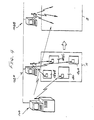
- Fig. 4 shows in sketch type form an arrangement which characterizes the system according to a first embodiment of the present invention.
- this system includes a main control station 100 and a plurality of stage controllers 102A, 102B .... which are operatively connected to the main one 100.
- stage controllers 102A, 102B .... which are operatively connected to the main one 100.
- stages A, B are shown for simplicity.
- stages A, B are shown for simplicity.
- the number of stages can be reduced if a relatively large number of operations are performed using the instant invention is extremely flexible.
- a main work station type AGV 120 on which a main work piece such as a vehicle chassis or the like 122 is supported can be moved sequentially from stage to stage while at least one auxiliary or stage AGV 124 (in this case three 124A, 124B, 124C are shown) remain in the instant stage and perform predetermined operations on each main work station 120 as it passes from stage to stage.
- auxiliary or stage AGV 124 in this case three 124A, 124B, 124C are shown
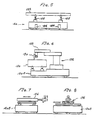
- Figs. 5 to 10 show various type of AGV vehicle which are used in each stage of the instant embodiment of the present invention.
- Fig. 5 shows a main work station type AGV (automatic guidance vehicle) 120 on which a main work piece 122 is supported.
- This vehicle is provided with jacks 126 which enable the vehicle to be stably supported on the work floor once the vehicle has assumed the required position in the appropriate stage.
- the main work station 120 further includes work piece support jacks 128 which permit the work piece to be raised and lowered etc., in a manner which facilitates work operations. If necessary the work piece 122 can be lowered to increase stablity during transit between stages which are spaced by a relatively long distance.
- Fig. 6 shows an AGV 124A which is arranged to support a sub-work piece or component 130 which is to be attached to the main one 122.
- This work piece can be attached as is, or after a number of preliminary operations such as having bolts inserted and tightened in place by a robot 132 which is supported on the vehicle.
- the robot is 132 equipped with arm 133 having a nut runner 134 provided on the end thereof.
- the nut runner 134 can be swung to a position in which work unrelated to the component 130 can be done on the main work piece 120 if so desired.
- FIGs. 7 and 8 show front and side elevational views of an AGV 124B which is provided with only a tool such as a nut runner equipped robot device 136 (it should be noted that any other suitable kind of tool or tools can be selectively mounted in this place if so desired).
- the tool can be moved about in the illustrated manner.
- This AGV can be moved to and about the main AGV 120 in a manner which enables various operations to be performed on the main work piece 122.
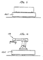
- Fig. 9 shows an AGV 124T which is adapted to only transport various components (no numeral) from storage sites to the work site; while Fig. 10 shows an AGV 124C which is equipped with a crane 138 ( mechanical hand) which is adapted to lift components from the transport AGV 124T and place them either on one of the auxiliary AGV or onto the main work piece 120 as the situation demands.
- a crane 138 mechanical hand
- the operation of the above type of arrangement is controlled via a program which is run in the main controller 100.
- This system is such that the main controller 100 issues control signals to the main work station AGV and to the stage controllers which in turn issue signals to the various auxiliary AGV assigned to the various stages.
- stage 1001 it is determined in stage 1001 whether vehicular unit instructions which are necessary for selectively moving the various AGV have been issued or not.
- the program flows to step 1002 wherein the appropriate AGV program or programs which are to be run by the stage controller are selected.
- the main controller is arranged to issue a control signal which induces the main AGV to move in the direction indicated by the bold arrow in a predetermined position in the first stage (for example) of the process.
- signals are issued to the stage controllers 102A, 102B etc., which contain data relating to the required movement and operations to be performed by the auxiliary or stage AGV.
- step 1003 an enquiry is performed to determine if the process has started or not. In the event that the process has not yet been initiated, the program recyles.
- a first movement program is run.
- This first program is designed (merely by way of example) to induce AGV 124A to move the component 130 supported thereon into position wherein a nut runner can to secure the same to the main work piece 122.
- a second movement program is run. This program is such as to, as shown in Fig. 12, designed to move the transport AGV 124T into proximity of the one on which the main work piece 122 is supported on, and to then move the crane equipped AGV 124C into position wherein the hand 138 can grasp the component which is supported on the transport vehicle 124T and place it in position on the main work piece 122.
- the above mentioned application discloses the use of two cameras which are arranged back to back and which can be disposed between the main work piece and the component to be mounted thereon, and used to develop images of the holes (for example) or sites which should be alinged in order to permit proper connection.
- the height and lateral position of the component is then adjusted until the two images exactly overlap one and other, the camera is withdrawn and the component moved into position on the main work piece.
- the height of the component is adjusted using the jacks while the lateral position be carried out either by moving the AGV itself or by providing a laterally action position control servo of a suitable type.
- the instant embodiment is such that the main work piece is to have only two components secured thereto in the first stage.
- the main work piece is to have only two components secured thereto in the first stage.
- the instant embodiment is such that the main work piece is to have only two components secured thereto in the first stage.
- the stage controllers and or the AGV to emit a guidance signal or signals which enables either the vehicles to determine their position and distance from the stage controller, or the stage controller to determine the distance and location of each of the vehicles from a given controller.
- step 1006 in the flow chart shown in Fig. 11 the presence or absence of an interlock signal is determined. While this signal is absent the program recyles and awaits the completion of the instant positioning and locating task or tasks.
- step 1007 a so called N movement program is run.
- This program is designed to induce the nut runner equipped AGV to move in and to insert and tighten the nuts and bolts (for example) which secure the correctly located components in position.
- Step 1008 monitors the operation of the N program and awaits the completion thereof. Following step 1008 a signal is issued to the main controller 100 indicating that the work in this stage is completed and that an instruction to move the main AGV to the next station can be issued.
- the main controller awaits the completion of all tasks before issuing a signal which will induce the train of main AGV to each move to the next stage.
- Figs. 13 to 15 show a second embodiment of the present invention.
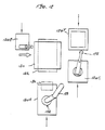
- a camera 200 is mounted above the floor 201 of the work place in a position wherein the positions of the various AGV can be observed.
- the camera 200 is used to produce an image of the work floor in a manner which enables the movement of the AGV to be monitored.
- Fig. 13 only two AGV are shown for simplicity of illustration and explanation. However, as will be appreciated this system is capable of being applied to an arrangement comprised of a large number of AGV which are arranged to define a production line for example.
- the operation of the above type of system is such that the camera 200 is operatively connected to a monitoring/control unit 202 wherein an image of the floor is developed. This image is transmitted to a monitor (display) 204 which which an operator can observer the situation.
- the system further includes a suitable interface or terminal 206 via which data can be inputted. As schematically shown, the data input is used to generate a movement pattern. This pattern is memorized and compared with the actual image produced.
- a digital image for example
- a similarly digitized image of the actual floor and the comparison used to indicate if the movement of the various elements is going according to a predetermined schedule or not.
- appropriate signals are fed to and received from a transport control device 208.
- This device is arranged to output and receive signals from a plurality of station controllers 210A, 210B (only two are shown in Fig. 14).
- Fig.15 shows in flow chart form the steps which characterize the operation of the second embodiment.
- the movement pattern which is required is read out of memory and installed ready for use.
- the input from the camera 200 is analysed in a manner which enables the position of each of the AGV to be determined and this data is read out.
- the two sets of positional data are compared and and in step 2004 a decision made as to whether the instant actual positions are correct or not.
- the rate at which the AGV are actually moving are compared with the values which should be occuring at this point of the process.
- steps 2004 and 2005 indicate an improper position or speed the program flow to step 2007 wherein an abnormality is indicated and the attention of an operator called to the fact that correction is required.
- step 2006 a "wait" for a predetermined period command is issued. Following this, step the program recycles to step 2001 and the program repeats.
- the distance each AGV has moved per run can be taken as the speed thereof.
- the concept of the invention is not limited to the above described two techniques and a combination of the two is clearly within the realm of possibility.
- the use of the camera equipped embodiment is deemed to be suited to the control of the transport AGV which may have to travel some distance to a storage site where they can be loaded with a predetermined component or componets required at one of the stages mentioned in connection with the first embodiment.
- laser beams and the like which can be beamed through the work site and used in combination with suitable photo responsive sensors etc., for guiding and/or alingment of the AGV.
- laser beams and the like can be used to transmit the control signals between the controllers and the AGV if so desired.
Landscapes
- Engineering & Computer Science (AREA)
- Physics & Mathematics (AREA)
- Aviation & Aerospace Engineering (AREA)
- Radar, Positioning & Navigation (AREA)
- Remote Sensing (AREA)
- General Physics & Mathematics (AREA)
- Automation & Control Theory (AREA)
- Mechanical Engineering (AREA)
- Robotics (AREA)
- Computer Vision & Pattern Recognition (AREA)
- Multimedia (AREA)
- Electromagnetism (AREA)
- Control Of Position, Course, Altitude, Or Attitude Of Moving Bodies (AREA)
Abstract
Description
- The present invention relates generally to a control system for unmanned vehicles and more specifically to a system which is particularly suited for use in production plants and which enables mass production and/or the like type of assembly work to be carried out using a plurality of such vehicles.
- Convential automotive production lines and the like are arranged basically in the form of a conveyor belt type system which carries work pieces from station to station. At each station various operation such as machining, welding, assembly and the like are performed. However, with such an arrangement a large tooling investment and amount of set up time and work is required and each time the production of a different work piece is required it is necessary to revise the line. This of course usually requires at least one portion of the line be totally dismantled and rebuilt in order to meet the requirements of the new product.
- When a production line which is set up for one type of automotive vehicle is changed to a different type, it is inherent that large scale revision of the assembly line must be made before production of the new vehicle can begin. For example, when a line which is set up for the production of a small sub-compact type vehicle is changed to one for a larger type having a larger engine (merely by way of example), it is necessary to at least change the section of the line wherein the chassis is formed, assembled, welded ect. Further, it is inevitable that the number and size of components and parts which must be fed from prepared stocks into the line will change.
- In recent times a large number of robots are used on assembly lines to perform welding and the like tasks. In the event of a model change such as mentioned above or the like occurs, a large number of the robots must be reprogrammed (retaught) in order to perform in the desired manner.
- In an effort to alleviate some the above programs it has been proposed in JP-A-58-192111 to provide autonomous vehicles which can carry components, parts and the like through a factor or like work place. This system has, as shown in Figs. 1 and 2, included the provision of
guide lines 1 andcontrol markers 2 on the road orfloor surface 3 on which the vehicle are arranged run. The vehicle are provided with two groups ofsensors 5 & 6, one which sense the guide line and the other which sense the position of the control markers. - The system used in the above mentioned vehicles is arranged in the manner illustrated in Fig. 3. As will be appreciated from this drawing, the outputs of a plurality of mark detection sensors 6 (four shown by way of example) are fed to a
sensor switching section 7. Thissection 7 is selectively controlled by a signal which is output by acontrol circuit 10 hereinafter referred to as a running control circuit) in a manner to determine which of the mark detection sensor outputs is fed to aposition determination section 12. This section as shown, is also supplied positional or map data from amemory 14. In accordance with this data input a signal is generated and supplied to a runningstatus determination section 16. Thissection 16 also receives an input from a movementpattern status section 18 and is arranged to output a control signal to the running control circuit orsection 10. In response to this input therunning control circuit 10 outputs two sensor switching data signals, one (as previously mentioned) to thesensor switching section 7 associated with themark detection sensors 6 and a second one to a secondsensor switching section 20 associated with a plurality (in this case 4)guide line sensors 5. Thiscircuit 10 also outputs a target speed data signal to aservo control section 22. - The latter mentioned section 32 receives a further data input in the form of a guidance error signal from the second
sensor switching section 20 via an A/D converter 24. In response to the target speed and guidance error signals theservo control section 22 outputs speed control signals to the left and right wheelmotor servo drivers 26, 28. - This system while proving somewhat effective has suffered from the drawback that at least
guide lines 1 andmarkers 2 have to be painted or otherwise provided on the floor of the factory or the like in which the above mentioned autonomous vehicles are arranged to operate. Accordingly, when it is desired to change from one production line layout to another, it is necessary to repaint the floor in a manner which covers over the old lines and establishes new ones appropriate for the new operations. This of course in the case of an automotive production line, means considerable work which must be precisely carried out in order to ensure accurate movement of the vehicles. Alternatively, it is possible to provide a number of patterns on the floor and operate the vehicles in manner to follow one of the patterns. However, this invites erroneous operation. Viz., in the case the lines or patterns become soiled or otherwise deteriorate in brightness and colour, it is likely that the autonomous vehicles will switch from following the intended pattern and follow one that is not in current use. - In the event of an erroneous sensor switching signal or sensor failure, for example, it is highly possible that the vehicle will turn left in stead of right, stop when it should not, or worse still continue when it should stop, and the like. If the batteries which power the device become low in power the vehicle is apt to stop in mid coure and block up the lanes defined by the painted lines and markers.
- Moreover, the number of different patterns that can be effectively painted is limited (by effective colours widths and the like) and requires a complex arrangement of markers in order to assure the correct maneuvering of the vehicles.
- Another arrangement proposed in order to permit control and movement of autonomous vehicles is disclosed in JM-A-61-11772. This arrangement has made use of a ultrasonic radar arrangement which is used to detect the position of a given item and provides circuits which are burried in the floor and which can be selective energized in manner which enables an autonomous vehicle to follow the electromagnetic flux which is produced.
- This system however, sufferes from the drawbacks of requiring the accurate (and expensive) disposition of the electric lines in the floor and the use of expensive radar units. Further, when used in a factory near welding equipment for example, the influence of noise proves to be a notable problem and can cause the vehicles to be erroneously guided away from the intended path. Accordingly, for this an other reasons, the system cannot be relied upon to provide the required stopping and starting of vehicles as is inherently required.
- It is an object of the present invention to provide a system which enables production lines to be established and changed with the minimum of construction costs and troubles and which is comprised essentially of a plurality of unmanned vehicular units.
- In brief, the above objects are achieved by using a plurality of unmanned self-propelled vehicles, some of which are designed to act as so called main vehicles and to carry a work piece from station to station, while other auxiliary vehicles are arranged to remain at each station and to carry components and assembly robots. Transport vehicle are used to move new components from storage sites to the work place. To facilitate large scale operations a camera can be used to observe the vehicles and compare with movement pattern with a predetermined desired one in order to ascertain appropriate movement.
- More specifically, a first aspect of the present invention is deemed to comprise a system which features: a first type of unmanned self-propelled vehicle, said first type of self-propelled vehicle being arranged to carry a main work piece to a predetermined position; a second type of unmanned self-propelled vehicle, said second type of self-propelled vehicle being arranged to carry components which are to be secured to the main work piece; a control system, said control system being arranged to transmit control orders to said first and second types of self-propelled vehicle in a manner which induces said said first type of self-propelled vehicle assume said predetermined position, and said second type of self-propelled vehicle to approach and dispose said component on a predetermined site on said main work piece.
- A second aspect of the present invention is deemed to comprise a system which features; a plurality of self-propelled vehicle; a camera, said camera being disposed in a location wherein a work site can be observed; a control arrangement, said control arrangement being operatively connected with said camera, said control arrangement being arranged to generate a preselected pattern which said plurality of self- propelled vehicle should assume, said control arangement being arranged develop an image indicative of the actual positions assumed by said plurality of self-propelled vehicle and to compare the image with said pattern and determine if the desired movement of said plurality of self-propelled vehicle is being achieved or not.
- A third aspect of the present invention is deemed to comprise a system which features: first and second stages; a main type of unmanned self-propelled vehicle, said main type of self-propelled vehicle being arranged to carry a main work piece to predetermined positions within each of said first and second stages, said main type of self-propelled vehicle being arranged to move sequentally from said first stage to said second stage; first and second unmanned self-propelled vehicles of an auxiliary type, each of said first and second auxiliary type of self-propelled vehicle being arranged to carry components which are to be secured to the main work piece, the first of said auxiliary type of self propelled vehicle being arranged to remain in said first stage and the second of said auxiliary type of vehicle being arranged to remain in said second stage; a control system, said control system comprising a main controller and first and second stage controllers, said main controller being arranged to transmit control signals to said main type of self-propelled vehicle in a manner which induces said said main type of self propelled vehicle to sequentially assume said predetermined positions in said first and second stages, said stage controllers being arranged to transmit orders to the first and second auxiliary type of self-propelled vehicle in a manner which induces said first and second auxiliary type of self-propelled vehicle to selectively approach and dispose a component on a predetermined site on said main work piece.
-
- Figs. 1 to 3 show a prior art AGV (automatic guidance vehicle) discussed in the opening paragraphs of the instant disclosure;
- Fig. 4 is a sketch schematically showing the layout according to a first embodiment of the present invention;
- Figs. 5 to 10 show various vehicles which can be used in connection with the embodiments of the present invention;
- Fig. 11 is a flow chart depicting the steps which characterize the operation of the first embodiment of the present invention;
- Fig. 12 is a plan view showing an example of vehicular movement which can be achieved with the first embodiment of the present invention;
- Fig. 13 is an perspective sketch showing an arrangement which typifies a second embodiment of the present invention;
- Fig. 14 is a block diagram which depicts the arrangement and operation of the second embodiment; and
- Fig. 15 is a flow chart showing the steps which characterize the operation of the second embodiment of the present invention.
- Fig. 4 shows in sketch type form an arrangement which characterizes the system according to a first embodiment of the present invention. As shown, this system includes a
main control station 100 and a plurality of stage controllers 102A, 102B .... which are operatively connected to the main one 100. In this drawing only two stages A, B are shown for simplicity. However, as will be apparent, in the case of an automotive production line quite a large number of stages can be arranged in sequence depending on the number of operations performed at each stage. It should also be noted that the number of stages can be reduced if a relatively large number of operations are performed using the instant invention is extremely flexible. - By way of example only, to produce a production line, a main work station type AGV 120 on which a main work piece such as a vehicle chassis or the like 122 is supported can be moved sequentially from stage to stage while at least one auxiliary or stage AGV 124 (in this case three 124A, 124B, 124C are shown) remain in the instant stage and perform predetermined operations on each
main work station 120 as it passes from stage to stage. - Figs. 5 to 10 show various type of AGV vehicle which are used in each stage of the instant embodiment of the present invention. Fig. 5 shows a main work station type AGV (automatic guidance vehicle) 120 on which a
main work piece 122 is supported. This vehicle is provided withjacks 126 which enable the vehicle to be stably supported on the work floor once the vehicle has assumed the required position in the appropriate stage. In this instance themain work station 120 further includes work piece support jacks 128 which permit the work piece to be raised and lowered etc., in a manner which facilitates work operations. If necessary thework piece 122 can be lowered to increase stablity during transit between stages which are spaced by a relatively long distance. - Fig. 6 shows an
AGV 124A which is arranged to support a sub-work piece orcomponent 130 which is to be attached to the main one 122. This work piece can be attached as is, or after a number of preliminary operations such as having bolts inserted and tightened in place by arobot 132 which is supported on the vehicle. In this instance the robot is 132 equipped witharm 133 having anut runner 134 provided on the end thereof. - Depending on the arrangement of the various AGV and the type of product under manufacture, the
nut runner 134, of course, can be swung to a position in which work unrelated to thecomponent 130 can be done on themain work piece 120 if so desired. - Figs. 7 and 8 show front and side elevational views of an AGV 124B which is provided with only a tool such as a nut runner equipped robot device 136 (it should be noted that any other suitable kind of tool or tools can be selectively mounted in this place if so desired). In this instance the tool can be moved about in the illustrated manner. This AGV can be moved to and about the
main AGV 120 in a manner which enables various operations to be performed on themain work piece 122. - Fig. 9 shows an
AGV 124T which is adapted to only transport various components (no numeral) from storage sites to the work site; while Fig. 10 shows anAGV 124C which is equipped with a crane 138 ( mechanical hand) which is adapted to lift components from thetransport AGV 124T and place them either on one of the auxiliary AGV or onto themain work piece 120 as the situation demands. - Depending on the product which is being produced, the number of and type of auxiliary AGV which are used in each stage will of course vary.
- The operation of the above type of arrangement is controlled via a program which is run in the
main controller 100. This system is such that themain controller 100 issues control signals to the main work station AGV and to the stage controllers which in turn issue signals to the various auxiliary AGV assigned to the various stages. - The characteristic operations which are performed by the main controller are depicted in flow chart form in Fig. 11.
- As will be appreciated following the start of the program it is determined in stage 1001 whether vehicular unit instructions which are necessary for selectively moving the various AGV have been issued or not. In the case of a positive outcome the program flows to step 1002 wherein the appropriate AGV program or programs which are to be run by the stage controller are selected. It should be noted that the main controller is arranged to issue a control signal which induces the main AGV to move in the direction indicated by the bold arrow in a predetermined position in the first stage (for example) of the process. Following this, signals are issued to the stage controllers 102A, 102B etc., which contain data relating to the required movement and operations to be performed by the auxiliary or stage AGV.
- At
step 1003 an enquiry is performed to determine if the process has started or not. In the event that the process has not yet been initiated, the program recyles. - At
step 1004 following the initiation of movement, a first movement program is run. This first program is designed (merely by way of example) to induceAGV 124A to move thecomponent 130 supported thereon into position wherein a nut runner can to secure the same to themain work piece 122. At step 1005 a second movement program is run. This program is such as to, as shown in Fig. 12, designed to move thetransport AGV 124T into proximity of the one on which themain work piece 122 is supported on, and to then move the crane equippedAGV 124C into position wherein thehand 138 can grasp the component which is supported on thetransport vehicle 124T and place it in position on themain work piece 122. - It will be noted that the provision of positions sensors of the nature disclosed in copending United States Patent Application Serial No. 183, 982 filed on April 20, 1988 in the name of Yokoi et al can be provided on the appropriate AGV in a manner which faciliates the movement of the same and the elevation of the component to be position on and secured to the main work piece.
- The above mentioned application discloses the use of two cameras which are arranged back to back and which can be disposed between the main work piece and the component to be mounted thereon, and used to develop images of the holes (for example) or sites which should be alinged in order to permit proper connection. The height and lateral position of the component is then adjusted until the two images exactly overlap one and other, the camera is withdrawn and the component moved into position on the main work piece. In the instant arrangement, the height of the component is adjusted using the jacks while the lateral position be carried out either by moving the AGV itself or by providing a laterally action position control servo of a suitable type.
- It should be noted that, for the sake of explanation only, the instant embodiment is such that the main work piece is to have only two components secured thereto in the first stage. In the case of an automotive vehicle it is possible to use a number of transports AGV, and several crane AGV in a manner to bring and attached a considerable number of components to the vehicle in the first stage alone.
- Merely by way of example, it is further possible to provide sensors on each of the AGV which enable the vehicles to automatically distinguish one from the other and to align themselves in a manner which faciliates the appropriate approach and orientation with the main AGV on which the main work piece is supported. In addition and/or as an alternative to this, it is also possible to arrange the stage controllers (and or the AGV) to emit a guidance signal or signals which enables either the vehicles to determine their position and distance from the stage controller, or the stage controller to determine the distance and location of each of the vehicles from a given controller.
- At
step 1006 in the flow chart shown in Fig. 11 the presence or absence of an interlock signal is determined. While this signal is absent the program recyles and awaits the completion of the instant positioning and locating task or tasks. - When the interlock signal appears, the program flows to step 1007 wherein a so called N movement program is run. This program is designed to induce the nut runner equipped AGV to move in and to insert and tighten the nuts and bolts (for example) which secure the correctly located components in position.
-
Step 1008 monitors the operation of the N program and awaits the completion thereof. Following step 1008 a signal is issued to themain controller 100 indicating that the work in this stage is completed and that an instruction to move the main AGV to the next station can be issued. - In the case that a number of main AGV are in the line, the main controller awaits the completion of all tasks before issuing a signal which will induce the train of main AGV to each move to the next stage.
- Figs. 13 to 15 show a second embodiment of the present invention. In this arrangement a
camera 200 is mounted above thefloor 201 of the work place in a position wherein the positions of the various AGV can be observed. In this arrangement thecamera 200 is used to produce an image of the work floor in a manner which enables the movement of the AGV to be monitored. In Fig. 13 only two AGV are shown for simplicity of illustration and explanation. However, as will be appreciated this system is capable of being applied to an arrangement comprised of a large number of AGV which are arranged to define a production line for example. - The operation of the above type of system is such that the
camera 200 is operatively connected to a monitoring/control unit 202 wherein an image of the floor is developed. This image is transmitted to a monitor (display) 204 which which an operator can observer the situation. The system further includes a suitable interface orterminal 206 via which data can be inputted. As schematically shown, the data input is used to generate a movement pattern. This pattern is memorized and compared with the actual image produced. - As will be appreciated using suitable software it is possible to produce a digital image (for example) of the nature which can be superimposed with a similarly digitized image of the actual floor, and the comparison used to indicate if the movement of the various elements is going according to a predetermined schedule or not. In accordance with the outcome of this monitoring appropriate signals are fed to and received from a
transport control device 208. This device is arranged to output and receive signals from a plurality ofstation controllers - Fig.15 shows in flow chart form the steps which characterize the operation of the second embodiment. As will be appreciated following the start of the program the movement pattern which is required is read out of memory and installed ready for use. At
step 2002 the input from thecamera 200 is analysed in a manner which enables the position of each of the AGV to be determined and this data is read out. Instep 2003 the two sets of positional data are compared and and in step 2004 a decision made as to whether the instant actual positions are correct or not. Atstep 2005 the rate at which the AGV are actually moving are compared with the values which should be occuring at this point of the process. In the event that either ofsteps - On the other hand, in the event that both of the speed and positions of the AGV are correct then at step 2006 a "wait" for a predetermined period command is issued. Following this, step the program recycles to step 2001 and the program repeats.
- As will be appreciated, as the time at which the program repeats is essentially constant, the distance each AGV has moved per run can be taken as the speed thereof.
- It is to be understood that the concept of the invention is not limited to the above described two techniques and a combination of the two is clearly within the realm of possibility. The use of the camera equipped embodiment is deemed to be suited to the control of the transport AGV which may have to travel some distance to a storage site where they can be loaded with a predetermined component or componets required at one of the stages mentioned in connection with the first embodiment.
- It is within the scope of the invention to use laser beams and the like which can be beamed through the work site and used in combination with suitable photo responsive sensors etc., for guiding and/or alingment of the AGV. Of course laser beams and the like can be used to transmit the control signals between the controllers and the AGV if so desired.
Claims (11)
a first type of unmanned self-propelled vehicle, said first type of self-propelled vehicle being arranged to carry a main work piece to a predetermined position;
a second type of unmanned self-propelled vehicle, said second type of self-propelled vehicle being arranged to carry components which are to be secured to the main work piece;
a control system, said control system being arranged to transmit control orders to said first and second types of self-propelled vehicle in a manner which induces said said first type of self-propelled vehicle assume said predetermined position, and said second type of self-propelled vehicle to approach and dispose said component on a predetermined site on said main work piece.
a plurality of self-propelled vehicle;
a camera, said camera being disposed in a location wherein a work site can be observed;
a control arangement, said control arrangement being operatively connected with said camera, said control arrangement being arranged to generate a preselected pattern which said plurality of self- propelled vehicle should assume, said control arrangement being arranged develop an image indicative of the actual positions assumed by said plurality of self-propelled vehicle and to compare the image with said pattern and determine if the desired movement of said plurality of self-propelled vehicle is being achieved or not.
a first type of unmanned self-propelled vehicle, said first type of self-propelled vehicle being arranged to carry a main work piece to a predetermined position; and
a second type of unmanned self-propelled vehicle, said second type of self-propelled vehicle being arranged to carry components which are to be secured to the main work piece.
means defining first and second stages;
a main type of unmanned self-propelled vehicle, said main type of self-propelled vehicle being arranged to carry a main work piece to predetermined positions within each of said first and second stages, said main type of self-propelled vehicle being arranged to move sequentally from said first stage to said second stage;
first and second unmanned self-propelled vehicles of an auxiliary type, each of said first and second auxiliary type of self-propelled vehicle being arranged to carry components which re to be secured to the main work piece, the first of said auxiliary type of self propelled vehicle being arranged to remain in said first stage and the second of said auxiliary type of vehicle being arranged to remain in said second stage;
a control system, said control system comprising a main controller and first and second stage controllers, said main controller being arranged to transmit control signals to said main type of self-propelled vehicle in a manner which induces said said main type of self propelled vehicle to sequentially assume said predetermined positions in said first and second stages, said stage controllers being arranged to transmit orders to the first and second auxiliary type of self-propelled vehicle in a manner which induces said first and second auxiliary type of self-propelled vehicle to selectively approach and dispose of component on a predetermined site on said main work piece.
Applications Claiming Priority (4)
| Application Number | Priority Date | Filing Date | Title |
|---|---|---|---|
| JP211420/87 | 1987-08-27 | ||
| JP62211421A JP2666291B2 (en) | 1987-08-27 | 1987-08-27 | Production equipment using automated guided vehicles |
| JP211421/87 | 1987-08-27 | ||
| JP62211420A JPS6455607A (en) | 1987-08-27 | 1987-08-27 | Running monitoring device for automatically guided vehicle |
Publications (3)
| Publication Number | Publication Date |
|---|---|
| EP0304942A2 true EP0304942A2 (en) | 1989-03-01 |
| EP0304942A3 EP0304942A3 (en) | 1989-12-06 |
| EP0304942B1 EP0304942B1 (en) | 1994-08-10 |
Family
ID=26518628
Family Applications (1)
| Application Number | Title | Priority Date | Filing Date |
|---|---|---|---|
| EP88113972A Expired - Lifetime EP0304942B1 (en) | 1987-08-27 | 1988-08-26 | Production system using unmanned automatically guided vehicles |
Country Status (3)
| Country | Link |
|---|---|
| US (1) | US4926544A (en) |
| EP (1) | EP0304942B1 (en) |
| DE (1) | DE3851020T2 (en) |
Cited By (12)
| Publication number | Priority date | Publication date | Assignee | Title |
|---|---|---|---|---|
| EP0388288A1 (en) * | 1989-03-14 | 1990-09-19 | Renault Automation | Robotised system for handling |
| FR2680996A1 (en) * | 1991-09-11 | 1993-03-12 | Peugeot | FLEXIBLE PRODUCT MOUNTING WORKSHOP. |
| EP0541811A4 (en) * | 1991-05-28 | 1994-06-29 | Toshiba Kk | Working device |
| EP0433522B1 (en) * | 1987-10-26 | 1996-10-09 | Megamation Incorporated | Robotic system |
| ES2112190A1 (en) * | 1995-11-17 | 1998-03-16 | Univ Madrid Complutense | Moveable autonomous robot with a high level of sensory and processing ability for cooperative tasks |
| FR2916152A1 (en) * | 2007-05-14 | 2008-11-21 | Robosoft Sa | VERSATILE ROBOT |
| WO2008151345A3 (en) * | 2007-06-12 | 2009-05-14 | Profactor Res And Solutions Gm | Device for automatically docking application modules to a robot platform and device for providing and transporting application modules |
| US8761989B1 (en) | 2012-12-18 | 2014-06-24 | Jervis B. Webb Company | Method of material handling with automatic guided vehicles |
| US9014902B1 (en) | 2014-02-21 | 2015-04-21 | Jervis B. Webb Company | Method of material handling with automatic guided vehicles |
| EP2604523A3 (en) * | 2011-12-15 | 2015-05-20 | The Boeing Company | Automated assembly of panelized aircraft fuselages |
| WO2015070841A1 (en) * | 2013-11-18 | 2015-05-21 | Grenzebach Maschinenbau Gmbh | Method and device for order picking in warehouses largely by machine |
| US9868591B2 (en) | 2015-11-23 | 2018-01-16 | Kia Motors Corporation | Automated guided vehicle |
Families Citing this family (35)
| Publication number | Priority date | Publication date | Assignee | Title |
|---|---|---|---|---|
| US5075853A (en) * | 1989-02-17 | 1991-12-24 | Whs Robotics, Inc. | Replaceable vehicle control prom |
| US5125149A (en) * | 1989-04-28 | 1992-06-30 | Canon Kabushiki Kaisha | Method of accessing and assembling parts in an assembly apparatus incorporating mobile robots |
| IT1310493B1 (en) * | 1999-09-27 | 2002-02-18 | Gd Spa | AUTOMATIC MACHINE PROVIDED WITH AN OPERATING WHEEL WITH WIRELESS CONTROL. |
| AT412196B (en) | 2000-03-17 | 2004-11-25 | Keba Ag | METHOD FOR ASSIGNING A MOBILE OPERATING AND / OR OBSERVATION DEVICE TO A MACHINE AND OPERATING AND / OR OBSERVATION DEVICE THEREFOR |
| US6886651B1 (en) | 2002-01-07 | 2005-05-03 | Massachusetts Institute Of Technology | Material transportation system |
| GB2386969A (en) * | 2002-03-26 | 2003-10-01 | Mcmurtry Ltd | Autonomous vehicle for ground maintenance with a ground marking means |
| DE10335571A1 (en) * | 2003-07-31 | 2005-02-24 | Daimlerchrysler Ag | Robot aided production system, comprising mobile robots for different tasks communicating and adjusting as required |
| DE10335568B4 (en) * | 2003-07-31 | 2005-07-28 | Daimlerchrysler Ag | Robot system and method of use |
| DE10335570A1 (en) * | 2003-07-31 | 2005-02-24 | Daimlerchrysler Ag | Mobile work holding robot has body carrying a camera and system of multiple linear control struts holding magnetic work platform with interconnecting member to similar units |
| DE102006003969B4 (en) * | 2006-01-26 | 2007-12-27 | Daimlerchrysler Ag | Guided assembly cart |
| DE102006004054B3 (en) * | 2006-01-28 | 2007-06-06 | Ford Global Technologies, LLC, Dearborn | Motor vehicle e.g. passenger car, manufacturing arrangement, has robot control unit, and robot that is provided for applying adhesive on disks attached in vehicle, where entire arrangement is designed as portable unit on common platform |
| DE102007005029B4 (en) * | 2007-02-01 | 2010-09-02 | Christian Beer | Robot on a self-propelled workpiece carrier |
| US20080231466A1 (en) * | 2007-03-19 | 2008-09-25 | Halliburton Energy Services, Inc. | Facilitating the communication of connectively dissimilar well servicing industry equipment via a universal connection device |
| US8154419B2 (en) * | 2007-12-14 | 2012-04-10 | Halliburton Energy Services Inc. | Oilfield area network communication system and method |
| US20100217437A1 (en) * | 2009-02-24 | 2010-08-26 | Branko Sarh | Autonomous robotic assembly system |
| US8666546B2 (en) * | 2009-07-10 | 2014-03-04 | The Boeing Company | Autonomous robotic platform |
| US8616274B2 (en) | 2010-05-07 | 2013-12-31 | Halliburton Energy Services, Inc. | System and method for remote wellbore servicing operations |
| DE102011115938B4 (en) | 2011-10-13 | 2022-03-10 | Daimler Ag | Production plant with a plurality of volume-dependent extension stages and method for designing such a production plant |
| US8768559B1 (en) * | 2013-01-22 | 2014-07-01 | Qunomic Virtual Technology, LLC | Line projection system |
| US10683171B2 (en) | 2016-09-30 | 2020-06-16 | Staples, Inc. | Hybrid modular storage fetching system |
| US10589931B2 (en) | 2016-09-30 | 2020-03-17 | Staples, Inc. | Hybrid modular storage fetching system |
| WO2018064639A1 (en) | 2016-09-30 | 2018-04-05 | Staples, Inc. | Hybrid modular storage fetching system |
| CN107527115A (en) * | 2017-08-14 | 2017-12-29 | 震坤行工业超市(上海)有限公司 | Intelligent storage management method, device, system and unmanned intelligent storage equipment |
| DE102018104880A1 (en) | 2018-02-05 | 2019-08-08 | Eberspächer Exhaust Technology GmbH & Co. KG | transport system |
| EP3520971A1 (en) * | 2018-02-06 | 2019-08-07 | ABB Schweiz AG | Assembling parts in an assembly line |
| DE102018109495B4 (en) | 2018-04-20 | 2022-10-13 | Heron Innovations Factory Gmbh | Transport robot with loaded multi-axis robot |
| US11084410B1 (en) | 2018-08-07 | 2021-08-10 | Staples, Inc. | Automated guided vehicle for transporting shelving units |
| US11590997B1 (en) | 2018-08-07 | 2023-02-28 | Staples, Inc. | Autonomous shopping cart |
| US11630447B1 (en) | 2018-08-10 | 2023-04-18 | Staples, Inc. | Automated guided vehicle for transporting objects |
| US11059534B2 (en) * | 2018-12-18 | 2021-07-13 | GM Global Technology Operations LLC | Nondeterministic assembly system and method |
| US11180069B2 (en) | 2018-12-31 | 2021-11-23 | Staples, Inc. | Automated loading of delivery vehicles using automated guided vehicles |
| US11119487B2 (en) | 2018-12-31 | 2021-09-14 | Staples, Inc. | Automated preparation of deliveries in delivery vehicles using automated guided vehicles |
| US11124401B1 (en) | 2019-03-31 | 2021-09-21 | Staples, Inc. | Automated loading of delivery vehicles |
| WO2021059458A1 (en) * | 2019-09-26 | 2021-04-01 | 楽天株式会社 | Control device, mobile body, system, and method |
| US20210149416A1 (en) * | 2019-11-19 | 2021-05-20 | Grey Orange Pte. Ltd. | Method and system for facilitating operations in storage facilities |
Family Cites Families (11)
| Publication number | Priority date | Publication date | Assignee | Title |
|---|---|---|---|---|
| DE238756C (en) * | ||||
| US3805704A (en) * | 1971-07-20 | 1974-04-23 | P Schauffler | Transfer system |
| US4342536A (en) * | 1980-08-14 | 1982-08-03 | General Motors Corporation | Door-opener apparatus |
| DE3113086A1 (en) * | 1981-04-01 | 1983-01-20 | Johann F. Dipl.-Phys. 2000 Hamburg Hipp | Positioning sensor system for automatically controlled vehicles |
| GB2129161B (en) * | 1982-10-14 | 1986-02-26 | Industry The Secretary Of Stat | Automatic control of vehicles |
| US4543702A (en) * | 1984-05-14 | 1985-10-01 | Satoh Seiki Co., Ltd. | Fully automatic method and apparatus for assembling stick-type cosmetics |
| JPS61160368A (en) * | 1984-12-31 | 1986-07-21 | Masao Kaji | Automobile controlling robot |
| DD238756A1 (en) * | 1985-06-28 | 1986-09-03 | Rostock Dieselmotoren | DEVICE AND TOOL CHANGING SYSTEM |
| DE3526524A1 (en) * | 1985-07-24 | 1987-02-05 | Siegmund Kumeth | DEVICE FOR THE AUTOMATIC ASSEMBLY OF WORKPIECES OR WORKPIECE PARTS, AND METHOD FOR CONTROLLING SUCH A DEVICE |
| DE3686301T2 (en) * | 1985-08-30 | 1993-01-21 | Texas Instruments Inc | INTRINSICALLY SAFE BRAKE FOR A MULTI-WHEELED VEHICLE WITH MOTOR-CONTROLLED STEERING. |
| CA1312349C (en) * | 1986-11-08 | 1993-01-05 | Genzo Fuse | Robot apparatus |
-
1988
- 1988-08-26 DE DE3851020T patent/DE3851020T2/en not_active Expired - Fee Related
- 1988-08-26 EP EP88113972A patent/EP0304942B1/en not_active Expired - Lifetime
- 1988-08-26 US US07/236,876 patent/US4926544A/en not_active Expired - Lifetime
Cited By (18)
| Publication number | Priority date | Publication date | Assignee | Title |
|---|---|---|---|---|
| EP0433522B1 (en) * | 1987-10-26 | 1996-10-09 | Megamation Incorporated | Robotic system |
| EP0388288A1 (en) * | 1989-03-14 | 1990-09-19 | Renault Automation | Robotised system for handling |
| FR2644599A1 (en) * | 1989-03-14 | 1990-09-21 | Renault Automation | ROBOTIC HANDLING SYSTEM |
| EP0541811A4 (en) * | 1991-05-28 | 1994-06-29 | Toshiba Kk | Working device |
| US5525027A (en) * | 1991-05-28 | 1996-06-11 | Kabushiki Kaisha Toshiba | Working robot |
| FR2680996A1 (en) * | 1991-09-11 | 1993-03-12 | Peugeot | FLEXIBLE PRODUCT MOUNTING WORKSHOP. |
| EP0532372A1 (en) * | 1991-09-11 | 1993-03-17 | Automobiles Peugeot | Flexible workshop for assembling products |
| ES2112190A1 (en) * | 1995-11-17 | 1998-03-16 | Univ Madrid Complutense | Moveable autonomous robot with a high level of sensory and processing ability for cooperative tasks |
| FR2916152A1 (en) * | 2007-05-14 | 2008-11-21 | Robosoft Sa | VERSATILE ROBOT |
| WO2008149018A3 (en) * | 2007-05-14 | 2009-01-29 | Robosoft | Domestic robot assistant having a rolling chassis |
| WO2008151345A3 (en) * | 2007-06-12 | 2009-05-14 | Profactor Res And Solutions Gm | Device for automatically docking application modules to a robot platform and device for providing and transporting application modules |
| EP2604523A3 (en) * | 2011-12-15 | 2015-05-20 | The Boeing Company | Automated assembly of panelized aircraft fuselages |
| US9090357B2 (en) | 2011-12-15 | 2015-07-28 | The Boeing Company | Method of assembling panelized aircraft fuselages |
| US9205933B2 (en) * | 2011-12-15 | 2015-12-08 | The Boeing Company | Automated assembly of panelized aircraft fuselages |
| US8761989B1 (en) | 2012-12-18 | 2014-06-24 | Jervis B. Webb Company | Method of material handling with automatic guided vehicles |
| WO2015070841A1 (en) * | 2013-11-18 | 2015-05-21 | Grenzebach Maschinenbau Gmbh | Method and device for order picking in warehouses largely by machine |
| US9014902B1 (en) | 2014-02-21 | 2015-04-21 | Jervis B. Webb Company | Method of material handling with automatic guided vehicles |
| US9868591B2 (en) | 2015-11-23 | 2018-01-16 | Kia Motors Corporation | Automated guided vehicle |
Also Published As
| Publication number | Publication date |
|---|---|
| EP0304942B1 (en) | 1994-08-10 |
| DE3851020D1 (en) | 1994-09-15 |
| US4926544A (en) | 1990-05-22 |
| EP0304942A3 (en) | 1989-12-06 |
| DE3851020T2 (en) | 1995-03-30 |
Similar Documents
| Publication | Publication Date | Title |
|---|---|---|
| US4926544A (en) | Production system using unmanned automatically guided vehicles | |
| CN111712355B (en) | Assembling parts in an assembly line | |
| CN106181098A (en) | A kind of automatic production process equipment is switched fast flexiblesystem | |
| CN111619590A (en) | Port transportation equipment control system and control method | |
| US11059534B2 (en) | Nondeterministic assembly system and method | |
| CN116540593A (en) | Control system, method and medium of AGV composite type cooperative robot | |
| EP1286880B1 (en) | A method and a plant for assembly | |
| JP2023524472A (en) | Fastener supply system and method | |
| EP0359822B1 (en) | Orbit controlling method of robot | |
| JP2560302B2 (en) | Production method using unmanned vehicles | |
| JP2560317B2 (en) | Automatic guided vehicle | |
| JPH04223826A (en) | Production process management system | |
| JP2001005525A (en) | Unmanned transport system | |
| JP2611225B2 (en) | Automatic guided vehicle | |
| JP2816706B2 (en) | Driving instruction creation device for automatic guided vehicles | |
| JPH11134028A (en) | Self-propelled truck traveling system | |
| JPS6248474A (en) | Self-advancing type mobile robot | |
| JPH0612123A (en) | Drive control device for automated guided vehicles | |
| JP2770447B2 (en) | Operation control device for production line using automatic guided vehicles | |
| JPS6111815A (en) | Compensating system of positional shift of robot | |
| JPH0420740B2 (en) | ||
| JPH086640A (en) | Operation control method for carrier vehicles | |
| JPH04229309A (en) | Method for controlling movable system | |
| JP2527658B2 (en) | Welded steel joint manufacturing method | |
| EP0822474A1 (en) | System for orienting and guiding selfpropelled vehicles, and associated equipment |
Legal Events
| Date | Code | Title | Description |
|---|---|---|---|
| PUAI | Public reference made under article 153(3) epc to a published international application that has entered the european phase |
Free format text: ORIGINAL CODE: 0009012 |
|
| 17P | Request for examination filed |
Effective date: 19880922 |
|
| AK | Designated contracting states |
Kind code of ref document: A2 Designated state(s): DE ES FR GB |
|
| PUAL | Search report despatched |
Free format text: ORIGINAL CODE: 0009013 |
|
| AK | Designated contracting states |
Kind code of ref document: A3 Designated state(s): DE ES FR GB |
|
| 17Q | First examination report despatched |
Effective date: 19920305 |
|
| GRAA | (expected) grant |
Free format text: ORIGINAL CODE: 0009210 |
|
| AK | Designated contracting states |
Kind code of ref document: B1 Designated state(s): DE ES FR GB |
|
| PG25 | Lapsed in a contracting state [announced via postgrant information from national office to epo] |
Ref country code: FR Effective date: 19940810 Ref country code: ES Free format text: THE PATENT HAS BEEN ANNULLED BY A DECISION OF A NATIONAL AUTHORITY Effective date: 19940810 |
|
| REF | Corresponds to: |
Ref document number: 3851020 Country of ref document: DE Date of ref document: 19940915 |
|
| EN | Fr: translation not filed | ||
| PLBE | No opposition filed within time limit |
Free format text: ORIGINAL CODE: 0009261 |
|
| STAA | Information on the status of an ep patent application or granted ep patent |
Free format text: STATUS: NO OPPOSITION FILED WITHIN TIME LIMIT |
|
| 26N | No opposition filed | ||
| REG | Reference to a national code |
Ref country code: GB Ref legal event code: IF02 |
|
| PGFP | Annual fee paid to national office [announced via postgrant information from national office to epo] |
Ref country code: GB Payment date: 20060823 Year of fee payment: 19 |
|
| PGFP | Annual fee paid to national office [announced via postgrant information from national office to epo] |
Ref country code: DE Payment date: 20060824 Year of fee payment: 19 |
|
| REG | Reference to a national code |
Ref country code: GB Ref legal event code: 746 Effective date: 20070604 |
|
| GBPC | Gb: european patent ceased through non-payment of renewal fee |
Effective date: 20070826 |
|
| PG25 | Lapsed in a contracting state [announced via postgrant information from national office to epo] |
Ref country code: DE Free format text: LAPSE BECAUSE OF NON-PAYMENT OF DUE FEES Effective date: 20080301 |
|
| PG25 | Lapsed in a contracting state [announced via postgrant information from national office to epo] |
Ref country code: GB Free format text: LAPSE BECAUSE OF NON-PAYMENT OF DUE FEES Effective date: 20070826 |