EP0304581A2 - Temperatursteuerung vom Gebäuden - Google Patents
Temperatursteuerung vom Gebäuden Download PDFInfo
- Publication number
- EP0304581A2 EP0304581A2 EP88110169A EP88110169A EP0304581A2 EP 0304581 A2 EP0304581 A2 EP 0304581A2 EP 88110169 A EP88110169 A EP 88110169A EP 88110169 A EP88110169 A EP 88110169A EP 0304581 A2 EP0304581 A2 EP 0304581A2
- Authority
- EP
- European Patent Office
- Prior art keywords
- duct
- room
- supply air
- temperature
- group
- Prior art date
- Legal status (The legal status is an assumption and is not a legal conclusion. Google has not performed a legal analysis and makes no representation as to the accuracy of the status listed.)
- Granted
Links
Images


Classifications
-
- E—FIXED CONSTRUCTIONS
- E04—BUILDING
- E04B—GENERAL BUILDING CONSTRUCTIONS; WALLS, e.g. PARTITIONS; ROOFS; FLOORS; CEILINGS; INSULATION OR OTHER PROTECTION OF BUILDINGS
- E04B5/00—Floors; Floor construction with regard to insulation; Connections specially adapted therefor
- E04B5/02—Load-carrying floor structures formed substantially of prefabricated units
- E04B5/04—Load-carrying floor structures formed substantially of prefabricated units with beams or slabs of concrete or other stone-like material, e.g. asbestos cement
-
- E—FIXED CONSTRUCTIONS
- E04—BUILDING
- E04B—GENERAL BUILDING CONSTRUCTIONS; WALLS, e.g. PARTITIONS; ROOFS; FLOORS; CEILINGS; INSULATION OR OTHER PROTECTION OF BUILDINGS
- E04B5/00—Floors; Floor construction with regard to insulation; Connections specially adapted therefor
- E04B5/48—Special adaptations of floors for incorporating ducts, e.g. for heating or ventilating
-
- F—MECHANICAL ENGINEERING; LIGHTING; HEATING; WEAPONS; BLASTING
- F24—HEATING; RANGES; VENTILATING
- F24F—AIR-CONDITIONING; AIR-HUMIDIFICATION; VENTILATION; USE OF AIR CURRENTS FOR SCREENING
- F24F3/00—Air-conditioning systems in which conditioned primary air is supplied from one or more central stations to distributing units in the rooms or spaces where it may receive secondary treatment; Apparatus specially designed for such systems
- F24F3/044—Systems in which all treatment is given in the central station, i.e. all-air systems
-
- F—MECHANICAL ENGINEERING; LIGHTING; HEATING; WEAPONS; BLASTING
- F24—HEATING; RANGES; VENTILATING
- F24F—AIR-CONDITIONING; AIR-HUMIDIFICATION; VENTILATION; USE OF AIR CURRENTS FOR SCREENING
- F24F5/00—Air-conditioning systems or apparatus not covered by F24F1/00 or F24F3/00, e.g. using solar heat or combined with household units such as an oven or water heater
- F24F5/0089—Systems using radiation from walls or panels
- F24F5/0092—Systems using radiation from walls or panels ceilings, e.g. cool ceilings
Definitions
- the method according to the present invention follows a different path. According to this method, both the floor structure of a building with high thermal capacity and small air flows of low temperature, ⁇ 15°C, are utilized, but without giving rise to draught.
- the invention comprises floor structures, which in known manner consist of pre-fabricated hollow concrete slabs or concrete floor structures with cast-in ducts. Cooled supply air flows through the floor structure before it is supplied via a supply air device to the room unit in question.
- the cooled air On its passage through the floor structure the cooled air has taken up heat from the floor structure, and at its passage through the supply air device it has assumed a temperature well in agreement with the mean temperature of the floor structure, i.e. a temperature, which is lower than the room air temperature by one or some degrees.
- the floor and ceiling surfaces thus, constitute large cooling surfaces, which provide thermal stability to the room, at the same time as the supply air is fed to the room with a temperature, which does not give rise to draught.
- the invention instead makes use of the possibility of directing the greater part of the low-tempered supply air flow via a shunt-line past the greater part of the floor structure and thereafter possibly mix it with the remaining air flow, which at its passage through the floor structure has assumed the mean temperature of the floor structure, in order in this way to feed to the room a supply air with a temperature not giving rise to draught problems.
- the building comprises a number of rooms, two of which are shown in the drawing. Outside each room a corridor 4 is located, in the false ceiling of which a supply air duct 5 is connected to a hollow duct 7 located in the floor structure 2.
- the rooms 1 are defined toward the corridor 4 by a partition wall 3 and relative to each other in horizontal direction by partition walls 13.
- the supply air is fed from the duct 5 via throttling damper 6, throttle valve 8, duct 7, bend 10 and device 12 into rooms 1.
- the supply air which in duct 5 has a temperature below 15°C, after having passed the floor structure via duct 7 has assumed the temperature of the floor structure of about 21-23°C.
- the temperature of the room air is some degree higher than the temperature of the floor structure.
- the remaining part of the supply air due to the pressure drop in the throttle valve 8, takes the way via the bend 10 before it arrives at the connection 11 where it, after possible admixture and after having passed through the distance 11/12, arrives at the device 12 with a selected temperature, which does not cause draught sensation, for example higher than +16°C.
- the supply air in duct 5 can, for example, be in the temperature range +8 to +15°C. After having passed through room 1, the air flows out via overflow device 14 into the corridor space and then via a return air system is recirculated in conventional manner to the fan room.
- the damper motor 9 closes and the entire supply air flow passes the floor structure via the path 8,7,10,12.
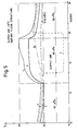
- Fig. 3 shows a connecting method alternative to the one shown in Fig. 2.
- the desired supply air temperature can be adjusted via the damper motor 9 to avoid draught problems.
- the supply air via duct 19 (Fig. 1) also can be fed via supply air devices 17 located at the floor.
- room 1 is located on the facade facing south, and a common fan unit supplies rooms both on the north and south, the rooms having momentarily a high internal load,preferably rooms facing south, after adjustment of the throttling damper 6 and possibly 8, upon opening of the damper motor 9 can receive a greater air flow for removing peak loads.
- the momentarily greater amount of surplus air is taken from the rooms, due to lower pressure difference, preferably on the facade facing north, which have not such an internal surplus heat , that direct cold via the path 9,11,12 is required.
- the proportions are about 45%, 45% and 10%, i.e. compared with previously more removed energy has been transferred from the floor structures to the ventilation air, resulting in a lower room temperature.
- a great part of the energy developed during daytime is stored in the floor structures and is removed during non-working hours, which causes a room temperature about 2°C higher than according to the invention. Due to the greater air flow (momentarily), the cooling effect increases by about 40% (Alt. II).
- the room is provided with false ceiling and an installed cooling effect, which maintains a constant room temperature of 22°C. Very little is stored here in walls and floor structure, because in the masses of the building no temperature variation takes place, the entire cooling effect is developed during working-hours (i.e. 08 - 17 o'clock) and the losses via windows and leakage are small as in Alt. 1, i.e. 10% (Alt. III).
- the added cooling effect corresponds here to 90% of the internal effect developed during daytime. This is to-day the method mostly used at the dimensioning of cooling installations.
- This method where there is the same mean room temperature during working-hours, a great difference in installed cooling effect is obtained, due to the spread of cooling effect over 24 hours, according to the invention, compared with an effect developed during nine hours, according to the conventional method.
- a building can be dimensioned to manage large momentary surplus heat by utilizing a small air flow with a very low temperature.
- the air flow can be restricted in that it more or less continuously cools down the floor structures, and when required instantaneously is permitted to increase over the room units concerned in temperature and flow, but without exceeding the draught criteria.
- connection 11 is made at the last duct in a group of ducts. It is hereby possible, with the help of the adjustability of damper 9, to achieve the necessary increase and, respectively, decrease in the temperature of the directly fed supply air, without the temperature level of the air flowing out of the device 12 giving rise to inconvenience, but yet achieving the desired air conditioning of the room in its entirety. It can prove possible that a good effect also is obtained when connection is made to the next to last duct.
- Fig. 5 the variation in temperature in room 1 during a 24-hour period is illustrated.
- the room is assumed at the calculations to have a surface of 10 m2, the outer wall faces south, the window is a three-glass window with a glass surface of 1.5 m2 and a Venetian blind in the central glass, the internal load consisting of lighting and terminal corresponding to an effect of 300 W between 8.00 o'clock and 17.00 o'clock.
- the outside temperature is 19°C ⁇ 6°C.
- One person stays in the room from 08.00 o'clock to 12.00 o'clock and from 13.00 o'clock to 17.00 o'clock.
- the temperature of the supply air before the floor structure is assumed to be 13°C.
- Curve 1 indicates the temperature variation in the room when the entire air flow of 60 m3/h passes the floor structure before it flows out into the room. The maximum temperature of the room is reached at about 16.00 o'clock.
- Curve 2 indicates the temperature of the supply air in the supply air device after the floor structure.
- Curve 4 indicates the supply air temperature +16°C in the supply air device,after admixture of about 20 m3/h supply air having passed the floor structure has taken place. The remaining part 65 m3/h has been supplied directly via path 11/12 according to Fig. 2.
- the computer calculations show, that due to the invention the room temperature could be lowered instantaneously by about 2°C without a greater cooling effect and a higher fan capacity having to be installed. See the difference between curves 1 and 3.
- Curve 3 indicates the temperature variations in the room at the air flow 60 m3/h between 18.00 o'clock and 10.00 o'clock, and a flow of 85 m3/h between 10.00 o'clock and 18.00 o'clock.
- the maximum room temperature here is about +23°C.
- the rooms in the example are oriented substantially toward north and south.
- 40% of the rooms i.e. the greater part of the rooms facing south at 10.00 o'clock exceed 22.5°C
- the throttle valves open and the flow increases from 60 m3/h to 85 m3/h, corresponding to an increase of about 40%.
- the remaining rooms then receive a smaller flow, i.e. The flow, thus, decreases in these rooms from 60 m3/h to 0.73 .
- 60 44 m3/h.
- the room temperature there follows curve 5, which during the entire 24 hours is immediately above +20°C. At a full air flow the corresponding temperature curve would be at about +19°C with resulting negative climate sensation.
- the above shows how the effect of the invention can be utilized at the control of the temperature in a building with different load preconditions at a minimum of installed cooling effect.
Landscapes
- Engineering & Computer Science (AREA)
- Architecture (AREA)
- Combustion & Propulsion (AREA)
- Mechanical Engineering (AREA)
- General Engineering & Computer Science (AREA)
- Chemical & Material Sciences (AREA)
- Civil Engineering (AREA)
- Electromagnetism (AREA)
- Physics & Mathematics (AREA)
- Structural Engineering (AREA)
- Life Sciences & Earth Sciences (AREA)
- Sustainable Development (AREA)
- Air Conditioning Control Device (AREA)
- Building Environments (AREA)
- Duct Arrangements (AREA)
- Organic Low-Molecular-Weight Compounds And Preparation Thereof (AREA)
Applications Claiming Priority (2)
| Application Number | Priority Date | Filing Date | Title |
|---|---|---|---|
| GB8719867A GB2208922B (en) | 1987-08-22 | 1987-08-22 | Temperature control of buildings |
| GB8719867 | 1987-08-22 |
Publications (3)
| Publication Number | Publication Date |
|---|---|
| EP0304581A2 true EP0304581A2 (de) | 1989-03-01 |
| EP0304581A3 EP0304581A3 (en) | 1990-06-20 |
| EP0304581B1 EP0304581B1 (de) | 1993-01-07 |
Family
ID=10622663
Family Applications (1)
| Application Number | Title | Priority Date | Filing Date |
|---|---|---|---|
| EP88110169A Expired - Lifetime EP0304581B1 (de) | 1987-08-22 | 1988-06-25 | Temperatursteuerung vom Gebäuden |
Country Status (5)
| Country | Link |
|---|---|
| US (1) | US4830275A (de) |
| EP (1) | EP0304581B1 (de) |
| DE (1) | DE3877280T2 (de) |
| GB (1) | GB2208922B (de) |
| NO (1) | NO164943C (de) |
Cited By (3)
| Publication number | Priority date | Publication date | Assignee | Title |
|---|---|---|---|---|
| EP0637721A1 (de) * | 1993-08-06 | 1995-02-08 | Sulzer Infra Management Services Ag | Verfahren zum Klimatisieren eines Gebäudeinnenraumes |
| EP1136761A1 (de) * | 2000-03-21 | 2001-09-26 | Hans Dr. Viessmann | Belüftbare Bodenplatte |
| EP1828687A4 (de) * | 2004-11-08 | 2010-12-15 | R L I Byggdata Aktiebolag | Verringerung von stromverbrauch |
Families Citing this family (4)
| Publication number | Priority date | Publication date | Assignee | Title |
|---|---|---|---|---|
| SE9200799L (sv) * | 1992-03-16 | 1993-09-17 | Rli Byggdata Ab | Anordning vid uppvärmning och ventilation av utrymmen |
| GB9407854D0 (en) * | 1994-04-20 | 1994-06-15 | Barnard Nicholas I | Building structures and methods of controlling the temperature of an interior space defined by such structures |
| EP2281981B1 (de) * | 2009-07-31 | 2015-12-02 | G.S. Hofman Holding B.V. | Parkgarage |
| US12504192B2 (en) | 2022-01-21 | 2025-12-23 | Laken And Associates Inc. | Predictive building air flow management for indoor comfort thermal energy storage with grid enabled buildings |
Family Cites Families (13)
| Publication number | Priority date | Publication date | Assignee | Title |
|---|---|---|---|---|
| US1986893A (en) * | 1929-11-04 | 1935-01-08 | Harold S Hasbrouck | Steam heater for motor vehicles |
| US2392240A (en) * | 1943-10-06 | 1946-01-01 | Frankel Enrique | System for heating, cooling, and air conditioning of buildings |
| US2559871A (en) * | 1949-08-24 | 1951-07-10 | Frazer W Gay | House structure and heating system therefor |
| US2917240A (en) * | 1956-08-24 | 1959-12-15 | Schwarzmayr Ludwig | Combustion gas heating system |
| US3013397A (en) * | 1960-06-14 | 1961-12-19 | Meckler Gershon | Perimeter heat transfer system for buildings |
| NL121460C (de) * | 1961-01-27 | |||
| US3516347A (en) * | 1967-12-26 | 1970-06-23 | Douglass H May | Double plenum air distribution system |
| DE2525917C2 (de) * | 1975-06-11 | 1983-11-10 | Schmidt Reuter Ingenieurgesellschaft mbH & Co KG, 5000 Köln | Anordnung zum Belüften oder Klimatisieren von Aufenthaltsräumen |
| US4069973A (en) * | 1975-11-17 | 1978-01-24 | Edwards Douglas W | Thermal distribution and storage system for solar and other heating and cooling |
| US4103578A (en) * | 1976-07-08 | 1978-08-01 | Ducret Lucien C | Cable armor cutting machine |
| SE434287B (sv) * | 1978-10-25 | 1984-07-16 | Aeromator Trading Co Ab | Forfarande och anordning for klimatstyrning av byggnader |
| US4646966A (en) * | 1985-06-11 | 1987-03-03 | Argon Corporation | Personalized air conditioning |
| CA1274111A (en) * | 1985-07-05 | 1990-09-18 | Leslie Phipps | Zoned air conditioning system |
-
1987
- 1987-08-22 GB GB8719867A patent/GB2208922B/en not_active Expired - Lifetime
-
1988
- 1988-06-25 DE DE8888110169T patent/DE3877280T2/de not_active Expired - Fee Related
- 1988-06-25 EP EP88110169A patent/EP0304581B1/de not_active Expired - Lifetime
- 1988-06-29 US US07/213,282 patent/US4830275A/en not_active Expired - Lifetime
- 1988-08-19 NO NO883737A patent/NO164943C/no not_active IP Right Cessation
Cited By (3)
| Publication number | Priority date | Publication date | Assignee | Title |
|---|---|---|---|---|
| EP0637721A1 (de) * | 1993-08-06 | 1995-02-08 | Sulzer Infra Management Services Ag | Verfahren zum Klimatisieren eines Gebäudeinnenraumes |
| EP1136761A1 (de) * | 2000-03-21 | 2001-09-26 | Hans Dr. Viessmann | Belüftbare Bodenplatte |
| EP1828687A4 (de) * | 2004-11-08 | 2010-12-15 | R L I Byggdata Aktiebolag | Verringerung von stromverbrauch |
Also Published As
| Publication number | Publication date |
|---|---|
| NO164943B (no) | 1990-08-20 |
| DE3877280D1 (de) | 1993-02-18 |
| GB2208922A (en) | 1989-04-19 |
| NO164943C (no) | 1990-11-28 |
| NO883737D0 (no) | 1988-08-19 |
| US4830275A (en) | 1989-05-16 |
| NO883737L (no) | 1989-02-23 |
| GB8719867D0 (en) | 1987-09-30 |
| DE3877280T2 (de) | 1993-05-19 |
| EP0304581A3 (en) | 1990-06-20 |
| GB2208922B (en) | 1992-04-01 |
| EP0304581B1 (de) | 1993-01-07 |
Similar Documents
| Publication | Publication Date | Title |
|---|---|---|
| Seyam | Types of HVAC systems | |
| US3945432A (en) | Air conditioning method and system | |
| US20090188985A1 (en) | Combined chiller and boiler HVAC system in a single outdoor operating unit | |
| US10295237B2 (en) | System and method for maintaining air temperature within a building HVAC system | |
| US3032323A (en) | Air conditioning systems | |
| EP0304581A2 (de) | Temperatursteuerung vom Gebäuden | |
| JP7228371B2 (ja) | 空調システム | |
| US5913723A (en) | Process and apparatus for air conditioning and/or heating, especially for apartment buildings | |
| US3967780A (en) | Air conditioning system | |
| DE3103549A1 (de) | Energiesparende gebaeudeheizung | |
| Murphy | High-performance VAV systems | |
| US2819023A (en) | Air conditioning apparatus | |
| US12566008B2 (en) | Method for controlling fan coil units and method for calculating heat transfer amount | |
| US3899022A (en) | Method and plant for regulating temperature by means of a subtempered air flow | |
| JP4345965B2 (ja) | 空調システム | |
| US2160132A (en) | Air conduit system for buildings | |
| CN118057087A (zh) | 模块化hvac-shw/dhw系统及其集成方法 | |
| US3459257A (en) | Room cooling system | |
| Moore | Potential and limitations for hydronic radiant slabs using waterside free cooling and dedicated outside air systems | |
| EP1407198B1 (de) | Lüftungsanlage | |
| FI56746C (fi) | Saett att aostadkomma avpassad temperatur i en lokal | |
| US3356134A (en) | Dual duct air conditioning systems | |
| Lstiburek | Multifamily Ventilation. | |
| Taylor et al. | Making UFAD systems work | |
| JP2019066123A (ja) | 空調システム及び施設 |
Legal Events
| Date | Code | Title | Description |
|---|---|---|---|
| PUAI | Public reference made under article 153(3) epc to a published international application that has entered the european phase |
Free format text: ORIGINAL CODE: 0009012 |
|
| 17P | Request for examination filed |
Effective date: 19880630 |
|
| AK | Designated contracting states |
Kind code of ref document: A2 Designated state(s): BE DE FR NL SE |
|
| PUAL | Search report despatched |
Free format text: ORIGINAL CODE: 0009013 |
|
| AK | Designated contracting states |
Kind code of ref document: A3 Designated state(s): BE DE FR NL SE |
|
| 17Q | First examination report despatched |
Effective date: 19910404 |
|
| GRAA | (expected) grant |
Free format text: ORIGINAL CODE: 0009210 |
|
| AK | Designated contracting states |
Kind code of ref document: B1 Designated state(s): BE DE FR NL SE |
|
| PG25 | Lapsed in a contracting state [announced via postgrant information from national office to epo] |
Ref country code: NL Effective date: 19930107 Ref country code: BE Effective date: 19930107 |
|
| REF | Corresponds to: |
Ref document number: 3877280 Country of ref document: DE Date of ref document: 19930218 |
|
| ET | Fr: translation filed | ||
| NLV1 | Nl: lapsed or annulled due to failure to fulfill the requirements of art. 29p and 29m of the patents act | ||
| PLBE | No opposition filed within time limit |
Free format text: ORIGINAL CODE: 0009261 |
|
| STAA | Information on the status of an ep patent application or granted ep patent |
Free format text: STATUS: NO OPPOSITION FILED WITHIN TIME LIMIT |
|
| 26N | No opposition filed | ||
| EAL | Se: european patent in force in sweden |
Ref document number: 88110169.5 |
|
| PGFP | Annual fee paid to national office [announced via postgrant information from national office to epo] |
Ref country code: FR Payment date: 19960621 Year of fee payment: 9 |
|
| PG25 | Lapsed in a contracting state [announced via postgrant information from national office to epo] |
Ref country code: FR Free format text: LAPSE BECAUSE OF NON-PAYMENT OF DUE FEES Effective date: 19980227 |
|
| REG | Reference to a national code |
Ref country code: FR Ref legal event code: ST |
|
| REG | Reference to a national code |
Ref country code: FR Ref legal event code: ST |
|
| EUG | Se: european patent has lapsed | ||
| PGFP | Annual fee paid to national office [announced via postgrant information from national office to epo] |
Ref country code: SE Payment date: 20060607 Year of fee payment: 19 |
|
| PGFP | Annual fee paid to national office [announced via postgrant information from national office to epo] |
Ref country code: DE Payment date: 20060628 Year of fee payment: 19 |
|
| EUG | Se: european patent has lapsed | ||
| PG25 | Lapsed in a contracting state [announced via postgrant information from national office to epo] |
Ref country code: DE Free format text: LAPSE BECAUSE OF NON-PAYMENT OF DUE FEES Effective date: 20080101 |
|
| PG25 | Lapsed in a contracting state [announced via postgrant information from national office to epo] |
Ref country code: SE Free format text: LAPSE BECAUSE OF NON-PAYMENT OF DUE FEES Effective date: 20070626 |