EP0303979A2 - Apparatus for measuring physical and/or chemical variables of liquids or gases - Google Patents
Apparatus for measuring physical and/or chemical variables of liquids or gases Download PDFInfo
- Publication number
- EP0303979A2 EP0303979A2 EP88113119A EP88113119A EP0303979A2 EP 0303979 A2 EP0303979 A2 EP 0303979A2 EP 88113119 A EP88113119 A EP 88113119A EP 88113119 A EP88113119 A EP 88113119A EP 0303979 A2 EP0303979 A2 EP 0303979A2
- Authority
- EP
- European Patent Office
- Prior art keywords
- sensor
- sensors
- plate
- tangential plane
- collar
- Prior art date
- Legal status (The legal status is an assumption and is not a legal conclusion. Google has not performed a legal analysis and makes no representation as to the accuracy of the status listed.)
- Pending
Links
- 239000007789 gas Substances 0.000 title claims abstract description 11
- 239000007788 liquid Substances 0.000 title claims abstract description 11
- 239000000126 substance Substances 0.000 title claims abstract description 6
- 238000007789 sealing Methods 0.000 claims abstract description 7
- 238000004140 cleaning Methods 0.000 claims description 5
- 239000011295 pitch Substances 0.000 claims description 3
- 230000003213 activating effect Effects 0.000 claims 1
- 230000008929 regeneration Effects 0.000 claims 1
- 238000011069 regeneration method Methods 0.000 claims 1
- 244000005700 microbiome Species 0.000 abstract description 5
- 238000009825 accumulation Methods 0.000 description 3
- 235000013305 food Nutrition 0.000 description 3
- 238000005259 measurement Methods 0.000 description 2
- 230000005855 radiation Effects 0.000 description 2
- 230000003321 amplification Effects 0.000 description 1
- 244000052616 bacterial pathogen Species 0.000 description 1
- 230000008033 biological extinction Effects 0.000 description 1
- 230000015572 biosynthetic process Effects 0.000 description 1
- 238000011088 calibration curve Methods 0.000 description 1
- 239000000356 contaminant Substances 0.000 description 1
- 239000013078 crystal Substances 0.000 description 1
- 235000013365 dairy product Nutrition 0.000 description 1
- 239000000428 dust Substances 0.000 description 1
- 238000005516 engineering process Methods 0.000 description 1
- 230000002349 favourable effect Effects 0.000 description 1
- 238000003754 machining Methods 0.000 description 1
- 239000000463 material Substances 0.000 description 1
- 238000000034 method Methods 0.000 description 1
- 238000003199 nucleic acid amplification method Methods 0.000 description 1
- 230000003287 optical effect Effects 0.000 description 1
- 239000002245 particle Substances 0.000 description 1
- 230000035515 penetration Effects 0.000 description 1
- 239000003566 sealing material Substances 0.000 description 1
- 230000001954 sterilising effect Effects 0.000 description 1
- 238000004659 sterilization and disinfection Methods 0.000 description 1
- 238000002604 ultrasonography Methods 0.000 description 1
Images

Classifications
-
- G—PHYSICS
- G01—MEASURING; TESTING
- G01L—MEASURING FORCE, STRESS, TORQUE, WORK, MECHANICAL POWER, MECHANICAL EFFICIENCY, OR FLUID PRESSURE
- G01L19/00—Details of, or accessories for, apparatus for measuring steady or quasi-steady pressure of a fluent medium insofar as such details or accessories are not special to particular types of pressure gauges
- G01L19/0007—Fluidic connecting means
- G01L19/0023—Fluidic connecting means for flowthrough systems having a flexible pressure transmitting element
-
- G—PHYSICS
- G01—MEASURING; TESTING
- G01L—MEASURING FORCE, STRESS, TORQUE, WORK, MECHANICAL POWER, MECHANICAL EFFICIENCY, OR FLUID PRESSURE
- G01L19/00—Details of, or accessories for, apparatus for measuring steady or quasi-steady pressure of a fluent medium insofar as such details or accessories are not special to particular types of pressure gauges
- G01L19/0007—Fluidic connecting means
- G01L19/0046—Fluidic connecting means using isolation membranes
-
- G—PHYSICS
- G01—MEASURING; TESTING
- G01L—MEASURING FORCE, STRESS, TORQUE, WORK, MECHANICAL POWER, MECHANICAL EFFICIENCY, OR FLUID PRESSURE
- G01L19/00—Details of, or accessories for, apparatus for measuring steady or quasi-steady pressure of a fluent medium insofar as such details or accessories are not special to particular types of pressure gauges
- G01L19/06—Means for preventing overload or deleterious influence of the measured medium on the measuring device or vice versa
Definitions
- the invention relates to a device for measuring chemical and / or physical quantities of liquids or gases in pipelines, in which a sensor is arranged in a connecting piece branching off the pipe.
- Devices of this type can contain mechanical sensors, for example pressure gauges, diaphragm seals or expansion vessels.
- electrical or electronic sensors are also used, which are used to determine the pressure, to measure the conductivity, the pH, the redox potential or the flow rate.
- Optical sensors are also used, for example, to carry out colorimetric or nephelometric determinations. In all these devices, it is known to either mount the sensors directly in the pipeline, which carries the liquid or gas to be measured, or in a nozzle, which is attached to the side of the pipeline.
- the variables detected by the sensor are usually converted into electrical signals and then, if necessary after amplification or other processing, registered or displayed by suitable instruments.
- the sensors or their holders are generally mounted according to aspects which depend on the space requirement or the easy accessibility of the sensor or its follow-up apparatus.
- this leads to the fact that dead spaces arise in the vicinity of the sensors, which in many cases are undesirable, and in some cases cannot even be tolerated.
- the invention has for its object to improve the known devices for measuring chemical and / or physical quantities of liquids or gases in pipelines in such a way that they protect against the accumulation of contaminants, microorganisms and the like. are largely insensitive and can therefore be used safely in the pharmaceutical and food industries.
- the sensor be arranged in the region of a tangential plane to the pipe cross section and fastened there in a sealing manner while avoiding gaps.
- a plate be arranged in the region of the tangential plane of the tube cross section and fastened there sealingly, avoiding gaps, which serves as a base plate for mounting the sensors.
- the Sensor with its end face directed towards the inside of the pipe is arranged in the region of a tangential plane to the pipe cross section and is sealed there, avoiding gaps.
- the arrangement of the sensor or more precisely the end face of the sensor in the region of a tangential plane means that the dead spaces mentioned are avoided at the endangered points, which preferably nests for microorganisms, but also for the accumulation of suspended matter and the like. form.
- the expression "in the region of a tangential plane" is intended to indicate that the end face of the sensor does not necessarily have to lie exactly in the tantential plane to the pipe cross section, but that certain small deviations from it can be tolerated. Such small deviations can arise because for the practical assembly of the sensor support collar or the like.
- Avoiding other gaps in the area of the sensor is also essential for the implementation of the invention. For this it is particularly important that where the sensor rests on its bearing, no possibility of penetration of deposits, microorganisms or the like. consists. It is most advantageous if the bearing surfaces of the collar on the one hand and the sensor or the plate on the other hand are machined flat and placed directly on top of one another without the interposition of a further seal.
- the sealing surfaces can be lapped, honed or polished; it is essential that they fit together without any gaps so that no liquid or gas can penetrate.
- interpose seals which will be done especially where a flat machining of the parts encounters difficulties. In this case, it is proposed that the sealing material used should not be O-rings or similar seals with a round cross section, but only flat seals.
- the proposed arrangement is particularly suitable for use in those areas where, above all, hygienically perfect conditions are important. These include the pharmaceutical industry, all areas of the food industry, especially brewery technology and the dairy industry, but also large areas of chemistry, especially organic chemistry.
- the application of the invention is not limited to these areas, but can also be used with advantage in the field of inorganic chemistry, since it often processes turbid liquids or dust-containing gases, which likewise lead to faults in the conventional type of sensor mounting.
- Another advantage results from the direct contact of the sensor with the medium to be measured all changes in the quantities to be measured are recorded and displayed practically without inertia.
- cleaning and sterilizing which must always be carried out from time to time, is very simple and can be done by applying steam. In the known measuring devices, it is much more difficult and accordingly takes more time to keep the dead spaces free of germs or deposits.
- sensors In principle, the type of sensors used is free within the scope of the invention. Pressure changes can be recorded via strain gauges or piezo crystals. However, capacitance-variable sensors are particularly preferred, the capacitance of which changes when the pressure is varied and is then recorded electronically in a known manner. However, sensors other than those mentioned can be mounted and arranged in the manner described with the same advantages.
- the lateral sealing should preferably - as mentioned - be carried out via a flat gasket or over machined surfaces in order to prevent dead spaces in these areas.
- Sensors of the type described are generally attached to a base within the housing.
- the base on the outside with a thread onto which a threaded ring is screwed, which in turn engages on the outside with the thread located there in the inside of the housing.
- the two concentric screw surfaces allow the holder or the sensor attached to it to penetrate into the measuring position by screwing the threaded ring, so that the holder itself and consequently the sensor can be gently brought into its measuring position.
- the base does not rotate when the threaded ring is screwed in.
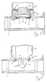
- the remaining corner rooms (7,8) are continuously flushed by flow vortices during the entire operation, which ensure a constant cleaning of these areas. This does not falsify the measured value.
- the course of the flow is particularly favorable when the sensor or the support plate rests on a collar (9), the edge (10) of which is directed toward the inside of the tube is chamfered or rounded.
- the senor (3) is placed on a ring-shaped projection, the collar (9), with the interposition of a flat seal (11).
- a base (12) on the back of the sensor which in the exemplary embodiment shown is pressed in the direction of the sensor with the aid of disc springs (13).
- a plate (14) which serves as a base plate for mounting the sensors (15, 15 '), which extend into the interior of the tube (1).
- sensors could, for example, pH measuring electrodes, conductivity electrodes or the like. be.
- the mounting plate (14) is arranged in the region of the tangential plane and is fastened there in a sealing manner while avoiding gaps.
- two measuring spigots (2,2 ') are attached to the side of the tube (1).
- This arrangement can be used if two physical and / or chemical measured variables are to be recorded simultaneously. However, it can also be used if, for example, turbidity measurements are to be carried out on the liquid or gas flowing through.
- the sensor (3) could be a photoelectric cell, for example, while a light source (16) is arranged in the opposite connector (2 '). The light from this light source penetrates the liquid (or gas) flowing in the tube (1) and is more or less weakened by its cloudiness.
- the sensor (3) which in this case can be a photoelectric cell (photocell), indicates the residual radiation arriving there; From the extinction of the radiation, the degree of turbidity of the irradiated medium can be inferred from a calibration curve.
- sensor (3) and light source (16) are sealingly mounted on the respective projections (collar) (9.9 '), either with the interposition of a flat gasket or directly on top of one another, in which case the sealing surfaces must be machined flat.
- a desired sensor (3) can be installed, for example, in the socket (2), while a cleaning device for the sensor (3) is located in the opposite socket (2 ').
- a cleaning device can be, for example, an ultrasound transmitter that is switched on from time to time and removes any deposits on the sensor surface.
Landscapes
- Physics & Mathematics (AREA)
- General Physics & Mathematics (AREA)
- Optical Measuring Cells (AREA)
- Apparatus Associated With Microorganisms And Enzymes (AREA)
- Measuring Fluid Pressure (AREA)
Abstract
Description
Die Erfindung betrifft eine Vorrichtung zum Messen chemischer und/oder physikalischer Größen an Flüssigkeiten oder Gasen in Rohrleitungen, bei der ein Sensor in einem vom Rohr abzweigenden Stutzen angeordnet ist. Derartige Vorrichtungen können mechanische Sensoren, beispielsweise Druckmesser, Druckmittler oder Ausdehnungsgefäße enthalten. In zahlreichen Fällen werden auch elektrische oder elektronische Sensoren eingesetzt, die zur Druckbestimmung, zur Messung der Leitfähigkeit, des pH-Wertes, des Redox-Potentiales oder der Durchflußmenge dienen. Auch optische Sensoren werden eingesetzt, um beispielsweise kolorimetrische oder nephelometrische Bestimmungen durchzuführen. Bei allen diesen Vorrichtungen ist es bekannt, die Sensoren entweder unmittelbar in der Rohrleitung, welche die zu messende Flüssigkeit oder das zu messende Gas führt, zu montieren oder aber in einem Stutzen, der seitlich an die Rohrleitung angesetzt ist. Die vom Sensor erfaßten Größen werden in aller Regel in elektrische Signale umgeformt und sodann, gegebenenfalls nach Verstärkung oder sonstiger Weiterverarbeitung durch geeignete Instrumente registriert oder angezeigt.The invention relates to a device for measuring chemical and / or physical quantities of liquids or gases in pipelines, in which a sensor is arranged in a connecting piece branching off the pipe. Devices of this type can contain mechanical sensors, for example pressure gauges, diaphragm seals or expansion vessels. In numerous cases, electrical or electronic sensors are also used, which are used to determine the pressure, to measure the conductivity, the pH, the redox potential or the flow rate. Optical sensors are also used, for example, to carry out colorimetric or nephelometric determinations. In all these devices, it is known to either mount the sensors directly in the pipeline, which carries the liquid or gas to be measured, or in a nozzle, which is attached to the side of the pipeline. The variables detected by the sensor are usually converted into electrical signals and then, if necessary after amplification or other processing, registered or displayed by suitable instruments.
Bei den vorbekannten Vorrichtungen dieser Art werden die Sensoren oder deren Halterungen in aller Regel nach Gesichtspunkten montiert, die sich nach dem Platzbedarf oder der leichten Zugänglichkei des Sensors bzw. deren Folgeapparate richten. Dies führt jedoch dazu, daß im Umfeld der Sensoren Toträume entstehen, die in vielen Fällen unerwünscht, teilweise sogar nicht tolerrierbar sind.In the case of the known devices of this type, the sensors or their holders are generally mounted according to aspects which depend on the space requirement or the easy accessibility of the sensor or its follow-up apparatus. However, this leads to the fact that dead spaces arise in the vicinity of the sensors, which in many cases are undesirable, and in some cases cannot even be tolerated.
In den erwähnten Toträumen werden sich nach einiger Zeit Schwebstoffe und andere Partikel absetzen, welche die Funktion beeinträchtigen oder gar unterbinden können. Insbesondere in der pharmazeutischen Industrie oder in der Lebensmittelindustrie führen solche Toträume zur Ansammlung von Mikro-Organismen, welche sich dort hartnäckig halten und nur durch eine generelle Desinfektion der Gesamtanlage zu beseitigen sind.After a while, suspended matter and other particles will settle in the dead spaces mentioned, which can impair or even prevent their function. In the pharmaceutical industry or in the food industry in particular, such dead spaces lead to the accumulation of microorganisms, which persist there and can only be eliminated by general disinfection of the entire system.
Der Erfindung liegt die Aufgabe zugrunde, die vorbekannten Vorrichtungen zum Messen chemischer und/oder physikalischer Größen an Flüssigkeiten oder Gasen in Rohrleitungen dahingehend zu verbessern, daß sie gegen die Ansammlung von Verunreinigungen, Mikro-Organismen u.dgl. weitgehend unempfindlich sind und deshalb in der pharmazeutischen Industrie sowie in der Lebensmittelindustrie bedenkenlos eingesetzt werden können. Zur Lösung dieser Aufgabe wird vorgeschlagen, daß der Sensor im Bereich einer Tangentialebene zum Rohrquerschnitt angeordnet und dort unter Vermeidung von Spalten dichtend befestigt ist. Für solche Sensoren, die in den Innenraum des Rohres hineinragen müssen, wird vorgeschlagen, daß im Bereich der Tangentialebene des Rohrquerschnittes eine Platte angeordnet und dort unter Vermeidung von Spalten dichtend befestigt ist, welche als Grundplatte für die Montage der Sensoren dient. Wesentlich für die vorliegende Erfindung ist somit die Tatsache, daß der Sensor mit seiner zum Rohrinnern gerichteten Stirnfläche im Bereich einer Tangentialebene zum Rohrquerschnitt angeordnet und dort unter Vermeidung von Spalten dichtend befestigt ist. Die Anordnung des Sensors oder genauer der Stirnfläche des Sensors im Bereich einer Tangentialebene bringt es mit sich, daß an den gefährdeten Stellen die erwähnten Toträume vermieden werden, welche bevorzugt Nester für Mikroorganismen, aber auch zur Ansammlung von Schwebestoffen u.dgl. bilden. Der Ausdruck "im Bereich einer Tangentialebene" soll andeuten, daß die Stirnfläche des Sensors nun nicht unbedingt exakt in der Tantentialebene zum Rohrquerschnitt liegen muß, sondern daß gewisse kleine Abweichungen davon tolierierbar sind. Solche kleinen Abweichungen können sich ergeben, weil zur praktischen Montage des Sensors Auflagekragen o.dgl. erforderlich sind, die im Hinblick auf die mechanische Stabilität in aller Regel eine Materialstärke von ca. 1 mm benötigen. Dadurch entsteht zwangsläufig eine Anordnung, bei der die Stirnfläche des Sensors geringfügig gegenüber der Tangentialebene zurückversetzt ist. Praktische Erfahrungen haben gezeigt, daß dies jedoch nicht störend ist, da sich durch die Strömung des zu messenden Mediums in den so entsptehenden Ecken Wirbel ausbilden, welche die Ecken von Ablagerungen freihalten oder wieder freiwaschen, so daß hier nicht von der Bildung von Toträumen gesprochen werden kann. In einer besonderen Ausführungsform der Erfindung wird vorgeschlagen, daß der Sensor oder die Platte im Bereich der Tangentialebene auf einem Kragen ruht, dessen zum Rohrinnern gerichtete Kante abgeschrägt oder abgerundet ist. Der erwähnte Bereich wird dadurch noch mehr dem Strömungsverlauf angepaßt, so daß Ablagerungen vermieden werden.The invention has for its object to improve the known devices for measuring chemical and / or physical quantities of liquids or gases in pipelines in such a way that they protect against the accumulation of contaminants, microorganisms and the like. are largely insensitive and can therefore be used safely in the pharmaceutical and food industries. To solve this problem, it is proposed that the sensor be arranged in the region of a tangential plane to the pipe cross section and fastened there in a sealing manner while avoiding gaps. For such sensors, which must protrude into the interior of the tube, it is proposed that a plate be arranged in the region of the tangential plane of the tube cross section and fastened there sealingly, avoiding gaps, which serves as a base plate for mounting the sensors. It is therefore essential for the present invention that the Sensor with its end face directed towards the inside of the pipe is arranged in the region of a tangential plane to the pipe cross section and is sealed there, avoiding gaps. The arrangement of the sensor or more precisely the end face of the sensor in the region of a tangential plane means that the dead spaces mentioned are avoided at the endangered points, which preferably nests for microorganisms, but also for the accumulation of suspended matter and the like. form. The expression "in the region of a tangential plane" is intended to indicate that the end face of the sensor does not necessarily have to lie exactly in the tantential plane to the pipe cross section, but that certain small deviations from it can be tolerated. Such small deviations can arise because for the practical assembly of the sensor support collar or the like. are required, which generally require a material thickness of approx. 1 mm in view of the mechanical stability. This inevitably creates an arrangement in which the end face of the sensor is set back slightly from the tangential plane. Practical experience has shown that this is not disturbing, however, since the flow of the medium to be measured creates vortices in the corners thus released, which keep the corners free of deposits or wash them free again, so that we do not speak of the formation of dead spaces here can. In a particular embodiment of the invention, it is proposed that the sensor or the plate rest on a collar in the region of the tangential plane, the edge of which is directed towards the inside of the tube is chamfered or rounded. The area mentioned is thereby even more adapted to the flow pattern, so that deposits are avoided.
Wesentlich für die Ausführung der Erfindung ist auch die Vermeidung von sonstigen Spalten im Bereich des Sensors. Hierzu ist es insbesondere wichtig, daß dort wo der Sensor auf seinem Lager aufliegt, keine Möglichkeit zum Eindringen von Ablagerungen, Mikroorganismen o.dgl. besteht. Am vorteilhaftesten ist es, wenn die Lagerflächen des Kragens einerseits und des Sensors oder der Platte andererseits plan bearbeitet und ohne Zwischenschaltung einer weiteren Dichtung unmittelbar aufeinandergelegt sind. Die Dichtflächen können zu diesem Zweck geläppt, gehohnt oder poliert sein; wesentlich ist, daß sie völlig spaltfrei aufeinanderpassen, so daß keinerlei Flüssigkeit oder Gas eindringen kann. Andererseits ist es auch möglich, Dichtungen zwischenzuschalten, was man insbesondere dort tun wird, wo eine plane Bearbeitung der Teile auf Schwierigkeiten stößt. Für diesen Fall wird vorgeschlagen, daß als Dichtmaterial nicht etwa O-Ringe oder ähnliche im Querschnitt runde Dichtungen sondern ausschließlich Flachdichtungen eingefügt werden.Avoiding other gaps in the area of the sensor is also essential for the implementation of the invention. For this it is particularly important that where the sensor rests on its bearing, no possibility of penetration of deposits, microorganisms or the like. consists. It is most advantageous if the bearing surfaces of the collar on the one hand and the sensor or the plate on the other hand are machined flat and placed directly on top of one another without the interposition of a further seal. For this purpose, the sealing surfaces can be lapped, honed or polished; it is essential that they fit together without any gaps so that no liquid or gas can penetrate. On the other hand, it is also possible to interpose seals, which will be done especially where a flat machining of the parts encounters difficulties. In this case, it is proposed that the sealing material used should not be O-rings or similar seals with a round cross section, but only flat seals.
Die vorgeschlagene Anordnung eignet sich besonders zum Einsatz in jenen Bereichen, in denen es vor allem auf hygienisch einwandfreie Verhältnisse ankommt. Hierzu zählen die pharmazeutische Industrie, sämtliche Bereiche der Lebensmittelindustrie, insbesondere die Brauereitechnik und die Milchwirtschaft, aber auch große Gebiete der Chemie, insbesondere der organischen Chemie. Die Anwendung der Erfindung ist aber nicht auf diese Bereiche beschränkt, sondern läßt sich auch im Bereich der anorganischen Chemie mit Vorteil einsetzen, da hier häufig trübstoffhaltige Flüssigkeiten oder staubhaltige Gase verarbeitet werden, die ebenfalls zu Störungen bei der herkömmlichen Art der Sensormontage führen. Ein weiterer Vorteil resultiert daraus, daß durch den unmittelbaren Kontakt des Sensors mit dem zu messenden Medium alle Änderung der zu messenden Größen praktisch trägheitslos erfaßt und angezeigt werden. Darüber hinaus ist das von Zeit zu grundsätzlich vorzunehmende Reinigen und Sterilisieren sehr einfach und kann durch Beaufschlagen mit Dampf erfolgen. Bei den bekannten Meßgeräten ist es wesentlich schwieriger und nimmt entsprechend mehr Zeit in Anspruch, die Toträume keimfrei oder ablagerungsfrei zu halten.The proposed arrangement is particularly suitable for use in those areas where, above all, hygienically perfect conditions are important. These include the pharmaceutical industry, all areas of the food industry, especially brewery technology and the dairy industry, but also large areas of chemistry, especially organic chemistry. However, the application of the invention is not limited to these areas, but can also be used with advantage in the field of inorganic chemistry, since it often processes turbid liquids or dust-containing gases, which likewise lead to faults in the conventional type of sensor mounting. Another advantage results from the direct contact of the sensor with the medium to be measured all changes in the quantities to be measured are recorded and displayed practically without inertia. In addition, cleaning and sterilizing, which must always be carried out from time to time, is very simple and can be done by applying steam. In the known measuring devices, it is much more difficult and accordingly takes more time to keep the dead spaces free of germs or deposits.
Grundsätzlich steht es im Rahmen der Erfindung frei, welche Art von Sensoren eingesetzt werden. So kann die Erfassung von Druckänderungen über Dehnungsmeßstreifen oder über Piezokristalle erfolgen. Besonders bevorzugt werden jedoch kapazitätsveränderliche Sensoren, deren Kapazität bei Variation des Druckes verändert und dann in bekannter Weise elektronisch erfaßt wird. Andere Sensoren als die genannten können jedoch mit den gleichen Vorteilen in der beschriebenen Weise montiert und angeordnet werden.In principle, the type of sensors used is free within the scope of the invention. Pressure changes can be recorded via strain gauges or piezo crystals. However, capacitance-variable sensors are particularly preferred, the capacitance of which changes when the pressure is varied and is then recorded electronically in a known manner. However, sensors other than those mentioned can be mounted and arranged in the manner described with the same advantages.
Der Sensor steht im eingebauten Zustand über einen Teil seiner Oberfläche in unmittelbarem Kontakt mit der im Rohr strömenden Flüssigkeit bzw. dem Gas. Die seitliche Abdichtung soll vorzugsweise - wie gesagt - über eine Flachdichtung oder über plan bearbeitete Flächen erfolgen, um auch in diesen Bereichen keine Toträume entstehen zu lassen. Zudem ist es leicht möglich, Flachdichtungen von außen her auszutauschen und durch eine neue zu ersetzen.When installed, the sensor is in direct contact with the liquid or gas flowing in the pipe over part of its surface. The lateral sealing should preferably - as mentioned - be carried out via a flat gasket or over machined surfaces in order to prevent dead spaces in these areas. In addition, it is easily possible to replace flat seals from the outside and to replace them with a new one.
Es wird empfohlen, die Kontaktfläche des Sensors kreisförmig zu wählen. Bei anderen geometrischen Formen, z.B. Rechtecken, bilden sich innerhalb des Sensors Spannungen aus, die kaum oder nur sehr schwierig beherrschbar sind und zu ungenauen Messungen Anlaß geben können.It is recommended to choose a circular contact surface for the sensor. In the case of other geometric shapes, for example rectangles, voltages form inside the sensor which are difficult or difficult to control and which can give rise to inaccurate measurements.
Sensoren der beschriebenen Art werden im allgemeinen über einen Sockel innerhalb des Gehäuses angebracht. Hierzu wird bevorzugt, den Sockel außenseitig mit einem Gewinde zu versehen, auf den ein Gewindering aufgeschraubt ist, der seinerseits außenseitig mit dem dort befindlichen Gewinde in die Innenseite des Gehäuses eingreift. Die beiden konzentrischen Schraubenflächen erlauben ein Eindringen der Fassung bzw. des daran befestigten Sensors in die Meßposition durch Verschrauben des Gewinderinges, so daß die Fassung selbst und demzufolge auch der Sensor schonend in seine Meßposition gebracht werden kann. Während des Eindrehens des Gewinderinges dreht sich der Sockel also nicht mit.Sensors of the type described are generally attached to a base within the housing. For this purpose, it is preferred to provide the base on the outside with a thread onto which a threaded ring is screwed, which in turn engages on the outside with the thread located there in the inside of the housing. The two concentric screw surfaces allow the holder or the sensor attached to it to penetrate into the measuring position by screwing the threaded ring, so that the holder itself and consequently the sensor can be gently brought into its measuring position. The base does not rotate when the threaded ring is screwed in.
Wählt man die Steigung auf beiden Seiten des Gewinderinges und folglich sowohl die zu der des Sockels relativ zu der des Gehäuses unterschiedlich, so können große Kräfte auch bei Verwendung vergleichsweise kleiner Schlüssel ausgeübt werden Hierdurch wird die Montage und Demontage des Sensors sowie seine Austauschbarkeit und die der Dichtung wesentlich vereinfacht und erleichtert. Des weiteren gestattet die Wahl von Gewinden unterschiedlicher Steigung ein feinfühliges und wohldosiertes Eindrehen.If you choose the pitch on both sides of the threaded ring and consequently both that of the base relative to that of the housing, different forces can be exerted even with the use of comparatively small keys Seal significantly simplified and facilitated. Furthermore, the selection of threads with different pitches allows a sensitive and carefully metered screwing in.
Die Erfindung wird im folgenden anhand der beigefügten Zeichnung näher erläutert. Es stellen dar:
- Fig. 1 einen vereinfachten Längsschnitt durch eine Ausführungsform;
- Fig. 2 einen Längsschnitt durch eine andere Ausführungsform mit Sensoren, welche in den Innenraum der Rohrleitung hineinreichen;
- Fig. 3 einen vereinfachten Längsschnitt durch eine weitere Ausführungsform mit zwei einander gegen überliegenden Meßanordnungen.
- Figure 1 is a simplified longitudinal section through an embodiment.
- 2 shows a longitudinal section through another embodiment with sensors which extend into the interior of the pipeline;
- Fig. 3 shows a simplified longitudinal section through a further embodiment with two against each other overlying measuring arrangements.
Wie schon vorher bemerkt, wäre es ideal, den Sensor bzw. dessen Stirnfläche (Meßfläche) exakt in derjenigen Ebene anzuordnen, die als Tangentialebene am Rohrquerschnitt anliegt. Dies ist indes in den meisten Fällen aus konstruktiven Gründen nicht möglich. Praktisch ausreichend ist es aber auch, wenn diese Ebene geringfügig, beispielsweise um einen oder wenige Millimeter, gegenüber der Tangentialebene zurückversetzt ist, wie dies in Fig. 1 dargestellt ist. Als Anhaltspunkt darf gelten, daß der "Bereich" der Tangentialebene möglichst wenig zurückversetzt sein soll; als äußerste Grenze tolerierbar ist etwa ein Bereich, der dem Durchmesser des Sensors entspricht. Das in der Rohrleitung (1) strömende Medium wird sich entlang des Strömungspfeiles (6) bewegen, wobei sich die Strömung in großen Bereichen gleichmäßig an die Oberfläche des Sensors anlegt. Die verbleibenden Eckräume (7,8) werden während des gesamten Betriebes kontinuierlich von Strömungswirbeln durchspült, welche für eine stetige Reinigung dieser Bereiche sorgen. Eine Verfälschung des Meßwertes tritt hierdurch nicht ein. Besonders günstig gestaltet sich der Strömungsverlauf, wenn der Sensor oder die Tragplatte auf einem Kragen (9) ruht, dessen zum Rohrinnern gerichtete Kante (10) abgeschrägt oder abgerundet ist.As previously noted, it would be ideal to arrange the sensor or its end face (measuring surface) exactly in the plane that is tangent to the pipe cross-section. In most cases, however, this is not possible for design reasons. However, it is also practically sufficient if this plane is set back slightly, for example by one or a few millimeters, with respect to the tangential plane, as is shown in FIG. 1. As a guide, the "area" of the tangential plane should be set back as little as possible; A range that corresponds to the diameter of the sensor can be tolerated as the extreme limit. The medium flowing in the pipeline (1) will move along the flow arrow (6), the flow spreading evenly over large areas of the sensor surface. The remaining corner rooms (7,8) are continuously flushed by flow vortices during the entire operation, which ensure a constant cleaning of these areas. This does not falsify the measured value. The course of the flow is particularly favorable when the sensor or the support plate rests on a collar (9), the edge (10) of which is directed toward the inside of the tube is chamfered or rounded.
Im dargestellten Ausführungsbeispiel ist der Sensor (3) unter Zwischenschaltung einer Flachdichtung (11) auf einen kranzförmigen Vorsprung, eben den Kragen (9) aufgelegt. Um den Sensor fest and die Flachdichtung anzupassen, befindet sich auf der Sensorrückseite ein Sockel (12), der im dargestellten Ausführungsbeispiel mit Hilfe von Tellerfedern (13) in Richtung des Sensors gedrückt wird.In the exemplary embodiment shown, the sensor (3) is placed on a ring-shaped projection, the collar (9), with the interposition of a flat seal (11). In order to firmly adapt the sensor to the flat gasket, there is a base (12) on the back of the sensor, which in the exemplary embodiment shown is pressed in the direction of the sensor with the aid of disc springs (13).
Bei der in Fig. 2 dargestellten Ausführungsform befindet sich im Bereich der Tangentialebene (5) eine Platte (14), welche als Grundplatte für die Montage der Sensoren (15,15′) dient, die in den Innenraum des Rohres (1) hineinreichen. Derartige Sensoren könnnten beispielsweise pH-Meßelektroden, Leitfähigkeitselektroden o.dgl. sein. Wesentlich ist auch hier, daß die Montageplatte (14) im Bereich der Tangentialebene angeordnet ist und dichtend unter Vermeidung von Spalten dort befestigt ist.In the embodiment shown in Fig. 2 is in the region of the tangential plane (5), a plate (14) which serves as a base plate for mounting the sensors (15, 15 '), which extend into the interior of the tube (1). Such sensors could, for example, pH measuring electrodes, conductivity electrodes or the like. be. It is also important here that the mounting plate (14) is arranged in the region of the tangential plane and is fastened there in a sealing manner while avoiding gaps.
Bei der in Fig. 3 dargestellten Ausführungsform sind an das Rohr (1) seitlich zwei Meßstutzen (2,2′) angesetzt. Diese Anordnung kann verwendet werden, wenn zwei physikalische und/oder chemische Meßgrößen gleichzeitig erfaßt werden sollen. Sie kann aber auch benutzt werden, wenn beispielsweise Trübungsmessungen an der durchströmenden Flüssigkeit oder dem durchströmenden Gas durchgeführt werden sollen. In diesem Fall könnte beispielsweise der Sensor (3) eine fotoelektrische Zelle sein, während im gegenüberliegenden Stutzen (2′) eine Lichtquelle (16) angeordnet ist. Das Licht dieser Lichtquelle durchdringt die im Rohr (1) strömende Flüssigkeit (oder das Gas) und wird von dessen Trübung mehr oder weniger geschwächt. Der Sensor (3), der in diesem Falle eine lichtelektrische Zelle (Fotozelle) sein kann, zeigt die dort ankommende Reststrahlung an; aus der Extinktion der Strahlung kann anhand einer Eichkurve auf den Trübungsgrad des durchstrahlten Mediums geschlossen werden. Auch in diesem Falle sind Sensor (3) und Lichtquelle (16) dichtend auf den jeweiligen Vorsprüngen (Kragen) (9,9′) gelagert, entweder unter Zwischenschaltung jeweils einer Flachdichtung oder aber unmittelbar aufeinander, wobei dann die Dichtflächen plan bearbeitet sein müssen.In the embodiment shown in Fig. 3, two measuring spigots (2,2 ') are attached to the side of the tube (1). This arrangement can be used if two physical and / or chemical measured variables are to be recorded simultaneously. However, it can also be used if, for example, turbidity measurements are to be carried out on the liquid or gas flowing through. In this case, the sensor (3) could be a photoelectric cell, for example, while a light source (16) is arranged in the opposite connector (2 '). The light from this light source penetrates the liquid (or gas) flowing in the tube (1) and is more or less weakened by its cloudiness. The sensor (3), which in this case can be a photoelectric cell (photocell), indicates the residual radiation arriving there; From the extinction of the radiation, the degree of turbidity of the irradiated medium can be inferred from a calibration curve. In this case, too, sensor (3) and light source (16) are sealingly mounted on the respective projections (collar) (9.9 '), either with the interposition of a flat gasket or directly on top of one another, in which case the sealing surfaces must be machined flat.
Bei einer anderen Ausführungsform kann ein gewünschter Sensor (3) beispielsweise in den Stutzen (2) eingebaut sein, während sich im gegenüberliegenden Stutzen (2′) eine Reinigungsvorrichtung für den Sensor (3) befindet. Eine derartige Reinigungsvorrichtung kann beispielsweise ein Ultraschallsender sein, der von Zeit zu Zeit eingeschaltet wird und etwa vorhandene Ablagerungen auf der Sensoroberfläche entfernt.In another embodiment, a desired sensor (3) can be installed, for example, in the socket (2), while a cleaning device for the sensor (3) is located in the opposite socket (2 '). Such a cleaning device can be, for example, an ultrasound transmitter that is switched on from time to time and removes any deposits on the sensor surface.
- 1 Rohrleitung1 pipe
- 2 Meßstutzen2 measuring spigots
- 3 Sensor3 sensor
- 4 Meßfläche von (3)4 measuring surface of (3)
- 5 Tangentialebene5 tangent plane
- 6 Strömungspfeil6 flow arrow
- 7 Eckraum7 corner room
- 8 Eckraum8 corner room
- 9 Kragen9 collar
- 10 Kante10 edge
- 11 Flachdichtung11 flat gasket
- 12 Sockel12 bases
- 13 Tellerfedern13 disc springs
- 14 Platte14 plate
- 15,15′ Sensoren15.15 ′ sensors
- 16 Lichtquelle16 light source
Claims (13)
dadurch gekennzeichnet,
daß der Sensor (3) im Bereich einer Tangentialebene (5) zum Rohrquerschnitt angeordnet und dort unter Vermeidung von Spalten dichtend befestigt ist.1. Device for measuring chemical and / or physical quantities of liquids or gases in pipelines, in which at least one sensor is arranged in a connecting piece branching off the pipe,
characterized,
that the sensor (3) is arranged in the region of a tangential plane (5) to the pipe cross-section and is sealed there, avoiding gaps.
dadurch gekennzeichnet,
daß im Bereich der Tangentialebene (5) eine Platte (14) angeordnet und dort unter Vermeidung von Spalten dichtend befestigt ist, die als Grundplatte für die Montage von in den Innenraum des Rohres (1) hineinragenden Sensoren (15,15′) dient.2. Device according to claim 1,
characterized,
that a plate (14) is arranged in the region of the tangential plane (5) and is sealed there, avoiding gaps, which serves as a base plate for the mounting of sensors (15, 15 ') projecting into the interior of the tube (1).
dadurch gekennzeichnet,
daß der Sensor (3) oder der Platte (14) im Bereich der Tangentialebene (5) auf einem Kragen (9) ruht, dessen zum Rohrinnern gerichtete Kante (10) abgeschrägt oder abgerundet ist.3. Device according to claim 1 or 2,
characterized,
that the sensor (3) or the plate (14) rests in the region of the tangential plane (5) on a collar (9), the edge (10) of which is directed towards the inside of the tube is chamfered or rounded.
dadurch gekennzeichnet,
daß die Lagerfläche des Kragens (9) einerseits und des Sensors (3) oder der Platte (14) anderereits plan bearbeitet und ohne Zwischenschaltung einer weiteren Dichtung unmittelbar aufeinandergelegt sind.4. Device according to one of claims 1 to 3,
characterized,
that the bearing surface of the collar (9) on the one hand and the sensor (3) or the plate (14) on the other hand are machined flat and placed directly on top of one another without the interposition of a further seal.
dadurch gekennzeichnet,
daß zum spaltlosen Abdichten zwischen die Lagerfläche des Sensors (3) oder der Platte (14) und der Lagerfläche des Kragens (9) eine Flachdichtung (11) eingefügt ist.5. Device according to one of claims 1 to 3,
characterized,
that a flat seal (11) is inserted for gapless sealing between the bearing surface of the sensor (3) or the plate (14) and the bearing surface of the collar (9).
dadurch gekennzeichnet,
daß die Sensoren (3) mechanisch oder hydraulisch wirkende Sensoren sind.6. Device according to one of the preceding claims,
characterized,
that the sensors (3) are mechanically or hydraulically acting sensors.
dadurch gekennzeichnet,
daß die Sensoren elektrisch oder elektronisch wirkende Sensoren sind.7. Device according to one of claims 1 to 5,
characterized,
that the sensors are electrically or electronically acting sensors.
dadurch gekennzeichnet,
daß die Sensoren optisch wirkende Sensoren sind.8. Device according to one of claims 1 to 5,
characterized,
that the sensors are optically acting sensors.
dadurch gekennzeichnet,
das Gehäuse des Meßfühlers ein Außen- und die Bohrung des Stutzens ein Innen-Gewinde aufweist, zwischen denen ein Gewindering verschraubbar ist, dessen äußeres und inneres Gewinde vorzugsweise unterschiedliche Steigungen aufweisen.9. Device according to one of the preceding claims,
characterized,
the housing of the sensor has an external thread and the bore of the connecting piece has an internal thread, between which a threaded ring can be screwed, the external and internal threads of which preferably have different pitches.
dadurch gekennzeichnet,
daß dem Stutzen (2) ein weiterer Stutzen (2′) gegenüberliegend angebracht sind.10. Device according to one of the preceding claims,
characterized,
that the nozzle (2) another nozzle (2 ') are attached opposite.
dadurch gekennzeichnet,
daß in den beiden Stutzen (2,2′) Meßfühler unterschiedlicher Art untergebracht sind.11. The device according to claim 10,
characterized,
that in the two nozzles (2.2 ') sensors of different types are accommodated.
dadurch gekennzeichnet,
daß im Stutzen (2′) ein Sender, beispielsweise eine Lichtquelle und im Stutzen (2) ein Empfänger, beispielsweise eine fotoelektrische Zelle angeordnet ist.12. The device according to claim 10,
characterized,
that in the nozzle (2 ') a transmitter, for example a light source and in the nozzle (2) a receiver, for example a photoelectric cell, is arranged.
dadurch gekennzeichnet,
daß im Stutzen (2) ein Meßfühler und im Stutzen (2′) ein System zum Regenerieren (Reinigen, Aktivieren u.ä.) des gegenüberliegenden Sensors untergebracht ist.13. The apparatus according to claim 10,
characterized,
that in the socket (2) a sensor and in the socket (2 ') a system for regeneration (cleaning, activating, etc.) of the opposite sensor is housed.
Applications Claiming Priority (2)
| Application Number | Priority Date | Filing Date | Title |
|---|---|---|---|
| DE3727296 | 1987-08-17 | ||
| DE19873727296 DE3727296A1 (en) | 1987-08-17 | 1987-08-17 | MANOMETER |
Publications (2)
| Publication Number | Publication Date |
|---|---|
| EP0303979A2 true EP0303979A2 (en) | 1989-02-22 |
| EP0303979A3 EP0303979A3 (en) | 1990-01-17 |
Family
ID=6333864
Family Applications (1)
| Application Number | Title | Priority Date | Filing Date |
|---|---|---|---|
| EP88113119A Pending EP0303979A3 (en) | 1987-08-17 | 1988-08-12 | Apparatus for measuring physical and/or chemical variables of liquids or gases |
Country Status (2)
| Country | Link |
|---|---|
| EP (1) | EP0303979A3 (en) |
| DE (1) | DE3727296A1 (en) |
Cited By (4)
| Publication number | Priority date | Publication date | Assignee | Title |
|---|---|---|---|---|
| EP0514575A1 (en) * | 1991-05-24 | 1992-11-25 | Werner Riemann | Analysis-module |
| DE4419593A1 (en) * | 1994-06-03 | 1995-12-07 | Fresenius Ag | Device for measuring the pressure of a medium |
| WO2001057488A1 (en) * | 2000-02-03 | 2001-08-09 | Siemens Aktiengesellschaft | Pressure sensor for detecting the pressure of a liquid |
| EP1531323A3 (en) * | 2003-11-14 | 2006-05-03 | VEGA Grieshaber KG | Mounting of pressure sensor |
Family Cites Families (12)
| Publication number | Priority date | Publication date | Assignee | Title |
|---|---|---|---|---|
| US2266315A (en) * | 1940-06-20 | 1941-12-16 | Gen Motors Corp | Pressure indicator |
| FR943238A (en) * | 1946-10-04 | 1949-03-02 | Methods and devices for measuring the pressure of a fluid circulating in a pipe | |
| GB741909A (en) * | 1952-10-04 | 1955-12-14 | Daimler Benz Ag | Improvements relating to the measurement of pressure or pressure oscillations in fluid conduits |
| AT354142B (en) * | 1976-11-02 | 1979-12-27 | List Hans | DEVICE FOR ELECTRICAL MEASUREMENT OF THE PRESSURE CURVE IN A PIPE |
| US4103555A (en) * | 1977-06-06 | 1978-08-01 | The United States Of America As Represented By The United States Department Of Energy | Pressure sensor for high-temperature liquids |
| US4484479A (en) * | 1978-04-05 | 1984-11-27 | Richard Eckhardt | Gas flow metering |
| US4165654A (en) * | 1978-04-14 | 1979-08-28 | Hammitt Frederick G | High response rate pressure pulse sensing probe with wide temperature range applicability |
| US4227419A (en) * | 1979-09-04 | 1980-10-14 | Kavlico Corporation | Capacitive pressure transducer |
| DE3431894C2 (en) * | 1983-10-13 | 1995-03-23 | Duebel Joerg Friedrich | Roller for the pressure treatment of webs, in particular for a squeeze unit for evenly dewatering textile webs |
| US4579001A (en) * | 1984-04-20 | 1986-04-01 | Craig Hosterman | Pressure relief valve with pressure indicating means |
| DE3418839A1 (en) * | 1984-05-21 | 1985-11-21 | Hoelzle & Chelius GmbH, 6078 Neu Isenburg | Device for colorimetry/photometry |
| DD258728A3 (en) * | 1985-12-23 | 1988-08-03 | Adw Ddr Inst Mechanik | PIEZOELECTRIC PRESSURE TRANSDUCER FOR MEASURING FLUID PRESSURE IN PIPING SYSTEMS |
-
1987
- 1987-08-17 DE DE19873727296 patent/DE3727296A1/en not_active Withdrawn
-
1988
- 1988-08-12 EP EP88113119A patent/EP0303979A3/en active Pending
Cited By (6)
| Publication number | Priority date | Publication date | Assignee | Title |
|---|---|---|---|---|
| EP0514575A1 (en) * | 1991-05-24 | 1992-11-25 | Werner Riemann | Analysis-module |
| DE4419593A1 (en) * | 1994-06-03 | 1995-12-07 | Fresenius Ag | Device for measuring the pressure of a medium |
| US5614677A (en) * | 1994-06-03 | 1997-03-25 | Fresenius Ag | Diaphragm gage for measuring the pressure of a fluid |
| WO2001057488A1 (en) * | 2000-02-03 | 2001-08-09 | Siemens Aktiengesellschaft | Pressure sensor for detecting the pressure of a liquid |
| US6684708B2 (en) | 2000-02-03 | 2004-02-03 | Siemens Ag | Pressure sensor for detecting the pressure of a liquid |
| EP1531323A3 (en) * | 2003-11-14 | 2006-05-03 | VEGA Grieshaber KG | Mounting of pressure sensor |
Also Published As
| Publication number | Publication date |
|---|---|
| EP0303979A3 (en) | 1990-01-17 |
| DE3727296A1 (en) | 1989-03-02 |
Similar Documents
| Publication | Publication Date | Title |
|---|---|---|
| EP0555739A1 (en) | Automatic pipetting device | |
| DE3006489C2 (en) | Measuring device | |
| DE3321454A1 (en) | PROBE | |
| DE3246731A1 (en) | Device for detecting the position of the piston of a working cylinder | |
| DE4343962A1 (en) | Linear displacement measuring device | |
| DE102016114565A1 (en) | measuring arrangement | |
| EP1425563A1 (en) | Pressure measuring apparatus | |
| EP0303979A2 (en) | Apparatus for measuring physical and/or chemical variables of liquids or gases | |
| EP0255084A2 (en) | Pressure measuring cell | |
| DE3811047A1 (en) | PROBE FOR CAPACITIVE MEASUREMENT OF PRESSURE IN GASES | |
| AT391950B (en) | DEVICE FOR MEASURING SAMPLE COMPONENTS IN A SAMPLE | |
| DE102012208893B4 (en) | Method for operating a measuring device of a pneumatic support control device | |
| WO2024260817A1 (en) | Cable feedthrough | |
| EP1591766B1 (en) | Optical measuring device and force sensor | |
| DE2321458C3 (en) | Device for diagnosing inflammatory periodontal disease | |
| DE3036164C2 (en) | Length measuring device | |
| DE3035167A1 (en) | Measurement device with strip scale for easy reading - uses reference scale point adjusted electrically or pneumatically | |
| DE8711127U1 (en) | manometer | |
| DE1903077A1 (en) | Automatic liquid transfer appts for - use in sequential analysis | |
| EP1602919A1 (en) | Measuring device for the survey of the transmittance of a coating | |
| DE3420018A1 (en) | DEVICE FOR MEASURING SPECIFIC PROPERTIES OF PARTICLES SUSPENDED IN A CARRIER MEDIUM | |
| AT357345B (en) | PRESSURE MEASURING DEVICE | |
| DE3018092C2 (en) | Device for checking ultrasonic testing devices | |
| DE8632565U1 (en) | Leak warning device | |
| DE2135076B2 (en) | Immersible probe for investigating liquid suspensions - has light source and two photocells to measure reflected light |
Legal Events
| Date | Code | Title | Description |
|---|---|---|---|
| PUAI | Public reference made under article 153(3) epc to a published international application that has entered the european phase |
Free format text: ORIGINAL CODE: 0009012 |
|
| AK | Designated contracting states |
Kind code of ref document: A2 Designated state(s): AT CH DE FR GB LI NL |
|
| PUAL | Search report despatched |
Free format text: ORIGINAL CODE: 0009013 |
|
| AK | Designated contracting states |
Kind code of ref document: A3 Designated state(s): AT CH DE FR GB LI NL |
|
| 18W | Application withdrawn |
Withdrawal date: 19900723 |
|
| D18W | Application withdrawn (deleted) | ||
| STAA | Information on the status of an ep patent application or granted ep patent |
Free format text: STATUS: THE APPLICATION IS DEEMED TO BE WITHDRAWN |
|
| 18D | Application deemed to be withdrawn |
Effective date: 19900718 |
|
| D18W | Application withdrawn (deleted) |