EP0303755B1 - Apparatus for granulating chicken excrements or similar materials - Google Patents
Apparatus for granulating chicken excrements or similar materials Download PDFInfo
- Publication number
- EP0303755B1 EP0303755B1 EP87890190A EP87890190A EP0303755B1 EP 0303755 B1 EP0303755 B1 EP 0303755B1 EP 87890190 A EP87890190 A EP 87890190A EP 87890190 A EP87890190 A EP 87890190A EP 0303755 B1 EP0303755 B1 EP 0303755B1
- Authority
- EP
- European Patent Office
- Prior art keywords
- rotor
- spring
- wings
- housing
- shaft
- Prior art date
- Legal status (The legal status is an assumption and is not a legal conclusion. Google has not performed a legal analysis and makes no representation as to the accuracy of the status listed.)
- Expired - Lifetime
Links
Images

Classifications
-
- B—PERFORMING OPERATIONS; TRANSPORTING
- B30—PRESSES
- B30B—PRESSES IN GENERAL
- B30B11/00—Presses specially adapted for forming shaped articles from material in particulate or plastic state, e.g. briquetting presses, tabletting presses
- B30B11/22—Extrusion presses; Dies therefor
- B30B11/228—Extrusion presses; Dies therefor using pressing means, e.g. rollers moving over a perforated die plate
-
- B—PERFORMING OPERATIONS; TRANSPORTING
- B01—PHYSICAL OR CHEMICAL PROCESSES OR APPARATUS IN GENERAL
- B01J—CHEMICAL OR PHYSICAL PROCESSES, e.g. CATALYSIS OR COLLOID CHEMISTRY; THEIR RELEVANT APPARATUS
- B01J2/00—Processes or devices for granulating materials, e.g. fertilisers in general; Rendering particulate materials free flowing in general, e.g. making them hydrophobic
- B01J2/20—Processes or devices for granulating materials, e.g. fertilisers in general; Rendering particulate materials free flowing in general, e.g. making them hydrophobic by expressing the material, e.g. through sieves and fragmenting the extruded length
-
- C—CHEMISTRY; METALLURGY
- C05—FERTILISERS; MANUFACTURE THEREOF
- C05F—ORGANIC FERTILISERS NOT COVERED BY SUBCLASSES C05B, C05C, e.g. FERTILISERS FROM WASTE OR REFUSE
- C05F3/00—Fertilisers from human or animal excrements, e.g. manure
- C05F3/06—Apparatus for the manufacture
-
- Y—GENERAL TAGGING OF NEW TECHNOLOGICAL DEVELOPMENTS; GENERAL TAGGING OF CROSS-SECTIONAL TECHNOLOGIES SPANNING OVER SEVERAL SECTIONS OF THE IPC; TECHNICAL SUBJECTS COVERED BY FORMER USPC CROSS-REFERENCE ART COLLECTIONS [XRACs] AND DIGESTS
- Y02—TECHNOLOGIES OR APPLICATIONS FOR MITIGATION OR ADAPTATION AGAINST CLIMATE CHANGE
- Y02A—TECHNOLOGIES FOR ADAPTATION TO CLIMATE CHANGE
- Y02A40/00—Adaptation technologies in agriculture, forestry, livestock or agroalimentary production
- Y02A40/10—Adaptation technologies in agriculture, forestry, livestock or agroalimentary production in agriculture
- Y02A40/20—Fertilizers of biological origin, e.g. guano or fertilizers made from animal corpses
-
- Y—GENERAL TAGGING OF NEW TECHNOLOGICAL DEVELOPMENTS; GENERAL TAGGING OF CROSS-SECTIONAL TECHNOLOGIES SPANNING OVER SEVERAL SECTIONS OF THE IPC; TECHNICAL SUBJECTS COVERED BY FORMER USPC CROSS-REFERENCE ART COLLECTIONS [XRACs] AND DIGESTS
- Y02—TECHNOLOGIES OR APPLICATIONS FOR MITIGATION OR ADAPTATION AGAINST CLIMATE CHANGE
- Y02P—CLIMATE CHANGE MITIGATION TECHNOLOGIES IN THE PRODUCTION OR PROCESSING OF GOODS
- Y02P20/00—Technologies relating to chemical industry
- Y02P20/141—Feedstock
- Y02P20/145—Feedstock the feedstock being materials of biological origin
Landscapes
- Chemical & Material Sciences (AREA)
- Engineering & Computer Science (AREA)
- Organic Chemistry (AREA)
- Mechanical Engineering (AREA)
- Manufacturing & Machinery (AREA)
- Chemical Kinetics & Catalysis (AREA)
- Crushing And Pulverization Processes (AREA)
Description
Die Erfindung betrifft eine Vorrichtung zum Granulieren von Hühnerexkrementen od. dgl. Stoffen, mit einem zylindrischen Gehäuse, das einen Einlaß und einen Auslaß aufweist und in dem ein Rotor exzentrisch gelagert ist, in dem wenigstens zwei radial angeordnete Flügel verschiebbar gelagert sind.The invention relates to a device for granulating chicken excrement or the like. Materials, with a cylindrical housing which has an inlet and an outlet and in which a rotor is eccentrically mounted, in which at least two radially arranged blades are slidably mounted.
Hühnerexkremente eignen sich gut zur Herstellung von Düngemitteln. Insbesondere in Hühnerzuchtanstalten fällt eine große Menge Hühnerexkremente an. Es besteht daher das Bedürfnis nach einer Vorrichtung zur Verarbeitung von Hühnerexkrementen, um diese vor Herstellung der Düngemittel zu granulieren. Zu diesem Zweck sind bisher Kolbenpressen versucht worden, doch haben sich diese als unbefriedigend erwiesen, weil einerseits der Leerhub des Kolbens zur Arbeit nichts beiträgt und anderseits das Granuliersieb oder -gitter in verhältnismäßig kurzer Zeit durch Hühnerfedern, Steinchen od. dgl. verstopft wird und sodann gereinigt werden muß, was einen Stillstand der Presse bedeutet.Chicken excrements are well suited for the production of fertilizers. There is a large amount of chicken excrement, especially in chicken breeding facilities. There is therefore a need for a device for processing chicken excrements in order to granulate them before the fertilizers are produced. Piston presses have so far been tried for this purpose, but these have proven to be unsatisfactory because, on the one hand, the empty stroke of the piston does not contribute to the work and, on the other hand, the pelletizing screen or grid is blocked in a relatively short time by chicken feathers, pebbles or the like and then must be cleaned, which means the press is at a standstill.
Aus der FR-A- 2 444 495 ist eine Granuliervorrichtung in Form einer Drehkolbenmaschine bekannt, in deren Einlaßschacht eine hin- und hergehend angetriebene Platte vorgesehen und an deren unterer Gehäuseseite mehrere Löcher ausgebildet sind.From FR-A-2 444 495 a pelletizing device in the form of a rotary piston machine is known, in the inlet shaft of which a reciprocating plate is provided and on the lower side of the housing a plurality of holes are formed.
Dem SU-Erfinderschein 625 762 ist eine Granuliervorrichtung mit einem zylindrischen Gehäuse und einer darin zentral gelagerten Welle entnehmbar, die mit zwei Quetschklingen versehen ist. Diese Klingen sind über je zwei teleskopartige Stäbe mit der Welle verbunden. Bei einem Verstopfen der an der Unterseite des Gehäuses vorgesehenen Öffnungen werden die Quetschklingen vom angesammelten Material radial nach innen gedrückt und verlieren ihre Wirksamkeit.The SU inventor's certificate 625 762 shows a pelletizing device with a cylindrical housing and a shaft centrally mounted therein, which is provided with two squeezing blades. These blades are connected to the shaft by two telescopic rods. If the openings provided on the underside of the housing become blocked, the pinched blades are pressed radially inwards by the accumulated material and lose their effectiveness.
Ziel der Erfindung ist die Beseitigung dieser Mängel und die Schaffung einer Granuliervorrichtung, die wirksam und kontinuierlich betrieben werden kann und bei der die Gefahr des Verstopfen durch unvermeidliche Fremdkörper vermieden ist.The aim of the invention is to remedy these shortcomings and Creation of a granulating device which can be operated effectively and continuously and which avoids the risk of clogging by inevitable foreign bodies.
Dieses Ziel wird mit einer Vorrichtung der eingangs genannten Art dadurch erreicht, daß erfindungsgemäß der Auslaß in an sich bekannter Weise in Form eines Siebes, Gitters od. dgl. ausgebildet ist und daß eine gerade Anzahl Flügel vorgesehen ist, von denen in an sich bekannter Weise je zwei einander diametral gegenüberliegen und ein Paar bilden, und daß die Flügel jedes Paares im Rotor sowohl gemeinsam als auch gegenseitig verschiebbar gelagert sowie mittels wenigstens einer Feder auseinandergespannt sind.This object is achieved with a device of the type mentioned at the outset in that, according to the invention, the outlet is designed in a manner known per se in the form of a sieve, grille or the like and that an even number of vanes are provided, of which in a manner known per se two diametrically opposed to each other and form a pair, and that the wings of each pair in the rotor are mounted both jointly and mutually displaceably and are spread apart by means of at least one spring.
Der Erfindung liegt die Idee zugrunde, das Prinzip der Flügelzellenpumpe auf eine Granulierpresse anzuwenden. Eine Flügelzellenpumpe bekannter Bauart würde sich allerdings für den beabsichtigten Zweck überhaupt nicht eignen, weil für diesen erheblich geringere Drehzahlen notwendig sind, wodurch die Flügel nicht mit der nötigen Kraft an das Gehäuse angepreßt bzw. von diesem abgehoben würden und ein auslaßseitig vorgesehenes Granuliersieb oder-gitter sofort verstopfte.The invention is based on the idea of applying the principle of the vane pump to a granulating press. A vane pump of a known type would not be suitable for the intended purpose, however, because considerably lower speeds are required for this purpose, as a result of which the vanes would not be pressed against or lifted off the housing with the necessary force and a pelletizing screen or grille provided on the outlet side immediately clogged.
Im Gegensatz zu bekannten Flügelzellenpumpen mit einer ungeraden Anzahl Flügel besitzt die erfindungsgemäße Vorrichtung paarweise angeordnete Flügel, die einander radial gegenüberliegen und insofern zusammenwirken, als sie gemeinsam im Rotor verschiebbar und von einer Feder auseinandergespannt sind, wodurch im Betrieb der Vorrichtung nur ein kurzer Federweg erforderlich ist. Obwohl der größte Hub eines Flügels im Rotor der doppelten Exzentrizität der Rotorachse bezüglich der Gehäuseachse entspricht, ist die Relativbewegung zweier diametral gegenüberliegender Flügel weitaus geringer.In contrast to known vane pumps with an odd number of vanes, the device according to the invention has vanes arranged in pairs, which lie radially opposite one another and cooperate insofar as they can be displaced together in the rotor and tensioned apart by a spring, so that only a short spring travel is required in the operation of the device . Although the largest stroke of a wing in the rotor corresponds to twice the eccentricity of the rotor axis with respect to the housing axis, the relative movement of two diametrically opposite wings is much less.
Daher kann nach einem weiteren Merkmal der Erfindung die Feder als Schraubendruckfeder, aber auch als Tellerfederpaket ausgebildet sein. Günstig ist, wenn wenigstens ein verstellbarer Federanschlag vorgesehen ist. Vorteilhafterweise weist die Feder eine progressive Kennlinie auf.Therefore, according to a further feature of the invention, the spring be designed as a helical compression spring, but also as a plate spring assembly. It is advantageous if at least one adjustable spring stop is provided. The spring advantageously has a progressive characteristic.
Bei einem bevorzugten Ausführungsbeispiel sind die Flügel jedes Paares auf zwei im Rotor gleitenden radialen teleskopartigen Stäben angebracht. Alternativ können die Flügel jedes Paares auf zwei im Rotor gleitenden radialen Stäben gelagert sein, die mit am Rotor anschlagenden Anschlägen versehen sind. Auf diese Weise kann die Wirksamkeit der Feder auf einen vorbestimmten Winkelbereich des Flügels im Gehäuse eingestellt werden.In a preferred embodiment, the wings of each pair are mounted on two radial telescopic rods sliding in the rotor. Alternatively, the wings of each pair can be mounted on two radial rods sliding in the rotor, which are provided with stops abutting the rotor. In this way, the effectiveness of the spring can be adjusted to a predetermined angular range of the wing in the housing.
Um das Verstopfen des auslaßseitigen Siebes oder Gitters noch besser zu verhindern, kann das äußere Flügelende eine Schneidkante aufweisen. Somit können allenfalls im Sieb bzw. Gitter steckende Hühnerfedern, Stroh od. dgl. abgeschnitten und vom nachkommenden Material leichter hindurchgedrückt werden. Alternativ oder zusätzlich kann das äußere Flügelende aus einer um eine zur Rotorachse parallelen Achse schwenkbaren Leiste bestehen. Dabei ist vorzuziehen, daß die innere Mantelwand des Gehäuses und gegebenenfalls die äußeren Flügelenden gehärtet sind.In order to prevent the sieve or grille on the outlet side from becoming blocked, the outer wing end can have a cutting edge. Thus, chicken feathers, straw or the like stuck in the sieve or grid can be cut off and pressed more easily by the material to come. Alternatively or additionally, the outer wing end can consist of a strip which can be pivoted about an axis parallel to the rotor axis. It is preferable that the inner casing wall of the housing and possibly the outer wing ends are hardened.
Zur Vereinfachung der Konstruktion, der Wartung und Reinigung kann der Rotor aus einer Welle, zwei auf dieser in axialem Abstand angeordneten Scheiben und mit diesen verbundenen Zylindersegmenten bestehen. Günstig ist weiters, wenn der Rotor mit einem an der Gehäuseaußenseite vorgesehenen Schwungrad gekuppelt ist. Um das Betriebsgeräusch der Vorrichtung zu vermindern, kann die Welle des Rotors elastisch gelagert sein.In order to simplify the construction, maintenance and cleaning, the rotor can consist of a shaft, two disks arranged on it at an axial distance and cylinder segments connected to them. It is also advantageous if the rotor is coupled to a flywheel provided on the outside of the housing. In order to reduce the operating noise of the device, the shaft of the rotor can be mounted elastically.
Da das Granulat bei einfach aufgebauter Vorrichtung und im Landmaschinenbau üblichen großen Toleranzen seitlich am Gehäuse austreten kann, kann schließlich der Auslaß mit über die Rotorachse reichenden seitlichen Abdeckungen abgedeckt sein.Since the granulate can emerge from the side of the housing with a simply constructed device and large tolerances customary in agricultural machinery construction, the outlet can finally be covered with side covers extending over the rotor axis.
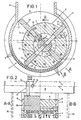
Die Erfindung wird im folgenden anhand vorteilhafter Ausführungsformen näher erläutert, die in den Zeichnungen dargestellt sind; es zeigen Fig. 1 einen Querschnitt durch die erfindungsgemäße Vorrichtung, Fig. 2 einen Axialschnitt durch die Vorrichtung, wobei die linke Hälfte einen Schnitt nach der Linie A-A und die rechte Hälfte einen Schnitt nach der Linie B-B in Fig. 1 darstellen, Fig. 3 einen Schnitt nach der Linie III-III in Fig. 2 zur Darstellung der Lagerung eines Paares Flügel auf einem Teleskopstab in größerem Maßstab, Fig. 4 eine Variante der Flügellagerung, in größerem Maßstab, Fig. 5 eine Ansicht in Richtung des Pfeiles V in Fig. 2 und Fig. 6 eine Variante des Flügelendes, in größerem Maßstab.The invention is explained in more detail below with the aid of advantageous embodiments which are illustrated in the drawings; 1 shows a cross section through the device according to the invention, FIG. 2 shows an axial section through the device, the left half representing a section along line AA and the right half representing a section along line BB in FIG. 1, FIG. 3 3 shows a section along the line III-III in FIG. 2 to show the mounting of a pair of wings on a telescopic rod on a larger scale, FIG. 4 shows a variant of the wing mounting on a larger scale, FIG. 5 shows a view in the direction of the arrow V in FIG 2 and 6 a variant of the wing end, on a larger scale.
Fig. 1 zeigt im Querschnitt eine vorteilhafte Ausführungsform der Erfindung, bei der in einem zylindrischen Gehäuse 1 exzentrisch ein Rotor 2 gelagert ist, dessen Achse 3 unterhalb der Gehäuseachse 4 verläuft. Das Gehäuse 1 ist im Betrieb mit waagrechter Achse 4 angeordnet und besitzt an seiner Oberseite einen Einlaß 5, an den ein Füllschacht 6 anschließt. Im unteren Gehäusebereich ist über einen Teil des Gehäusemantels, der sich in Drehrichtung A des Rotors 2 betrachtet etwa von der Ebene der Rotorachse 3 bis zur Stelle des geringsten Abstandes zwischen Gehäuse 1 und Rotor 2 erstreckt, ein Auslaß in Form eines Siebes 7 ausgebildet. Die Sieböffnungen sind runde Löcher 8, die in Reihen angeordnet und gegenseitig versetzt sind (s. Fig. 5), damit der gesamte Durchtrittsquerschnitt des Siebes 7 möglichst groß ist.1 shows in cross section an advantageous embodiment of the invention, in which a
Wie erwähnt, besteht der Rotor 2 zweckmäßigerweise aus einer Welle 9 mit zwei in einem der Gehäusebreite entsprechenden axialen Abstand angeordneten Scheiben 10, zwischen denen vier Zylindersegmente 11 angebracht sind. Je zwei benachbarte Zylindersegmente 11 begrenzen zwischen einander eine radiale Führung 12 für einen radial verschiebbaren Flügel 13.As mentioned, the
Es ist eine gerade Anzahl Flügel 13 vorgesehen, wobei jeweils zwei Flügel 13 einander diametral gegenüberliegend im Rotor 2 gelagert sind und ein Paar bilden. Je zwei einander gegenüber angeordnete, ein Paar bildende Flügel 13 wirken über zwei teleskopartige Stäbe 14 zusammen, die radial angeordnet sind und die Welle 9 des Rotors 2 durchsetzen.An even number of
Die Ausbildung dieser Stäbe 14 ist genauer in Fig. 3 dargestellt. Jeder Flügel 13 weist an seiner radialen Innenseite zwei im Abstand angeordnete Gewindebohrungen 15 auf, in die je ein Rohrstück 16 eingeschraubt ist. Die Rohrstücke 16 können in einer entsprechenden Bohrung 17 der Welle gleiten. Innerhalb der Rohrstücke 16 ist ein Bolzen 18 gleitend gelagert, der an beiden Enden je eine Gewindestange 19 trägt, auf die ein Federanschlag 20 für eine sich anderseits am Flügel 13 abstützende Schraubendruckfeder 21 aufgeschraubt ist. Mit Hilfe des Federanschlages 20 läßt sich die wirksame Federkraft einstellen, wobei die Feder 21 vorzugsweise eine progressive Kennlinie aufweist. Der Federanschlag 20 besitzt insbesondere einen dem Bolzen 18 gleichen Außendurchmesser, um als Führungskörper ein Verkanten des Rohrstückes 16 zu verhindern.The design of these
Fig. 4 zeigt eine Variante der Flügellagerung, bei der in einer ähnlichen Gewindebohrung 15 des Flügels 13 ein Federanschlag 20 eingeschraubt ist, der mittels einer Fixierschraube 22 fixiert ist. In der entsprechenden Bohrung 17 der Welle sitzt verschiebbar ein Gewindestab 23, auf den ein Anschlag 24 in Form einer Mutter und weiters ein als Führungskörper für den Flügel 13 dienender zweiter Federanschlag 25 aufgeschraubt sind. Zwischen den beiden Federanschlägen 20 und 25 ist ein Tellerfederpaket 26 eingesetzt, wobei die Tellerfedern ebenfalls eine progressive Kennlinie aufweisen oder unterschiedlich starke Tellerfedern hintereinander angeordnet sein können.Fig. 4 shows a variant of the wing mounting, in which a
Es ist zu bemerken, daß der lichte Abstand zwischen den beiden Anschlägen 24 größer als der Durchmesser der Welle 9 ist, um die vorhin erwähnte Verschiebbarkeit des Gewindestabes 23 zu ermöglichen. Der Verschiebeweg ist erheblich geringer als die doppelte Exzentrizität der Rotorachse 3.It should be noted that the clear distance between the two
Gemäß Fig. 1 ist das radial äußere Flügelende der Mantelwand des Gehäuses 1 angepaßt und mit einer Schneidkante 27 versehen; dabei ist zwecks Reibungsverringerung ein (in der Zeichnung nicht gezeigter) geringer Freiwinkel vorgesehen. Anderseits kann das äußere Flügelende gemäß Fig. 6 aus einer um eine zur Rotorachse parallele Achse 28 schwenkbaren, vorzugsweise austauschbar montierten Leiste 29 bestehen.1, the radially outer wing end of the jacket wall of the
Die innere Mantelwand des Gehäuses 1 und die äußeren Flügelenden bzw. die Leisten 29 sind gehärtet.The inner jacket wall of the
An den Stirnseiten des Gehäuses 1 kann je eine in Fig. 2 mit strichlierten Linien angedeutete Abdeckung 30 angebracht sein, die im wesentlichen über die Gehäusehöhe reicht und dazu dient, allfällig seitlich austretendes Granulat nach unten abzulenken.A
Zur Geräuschverminderung kann die Welle 9 des Rotors 2 elastisch gelagert sein; diese Maßnahme schützt außerdem die Flügel und den Rotor vor Beschädigungen durch Fremdkörper, z.B. in den Sieblöchern sitzenden Steinchen. Weiters ist zweckmäßig, die Welle 9 mit einem Schwungrad zu kuppeln, wobei dieses im Falle eines Antriebes über ein Untersetzungsgetriebe an der Eingangswelle desselben oder der Ausgangswelle des Antriebsmotors vorgesehen ist.To reduce noise, the
Im Betrieb der Vorrichtung gelangen die durch den Füllschacht 6 zugeführten Hühnerexkremente durch den Einlaß 5 ins Innere des Gehäuses 1, werden dort von einem der Flügel 13 erfaßt und in Richtung des Pfeiles A vorgeschoben. In dem sich nach unten verengenden Raum zwischen Gehäuse 1 und Rotor 2 werden die Exkremente gepreßt und durch die Löcher 8 des Siebes 7 ausgestoßen sowie im Zusammenwirken mit den Flügeln 13 granuliert. Das Granulat fällt sodann nach unten in nicht gezeigte Behälter oder Transporteinrichtungen. Allfällig zwischen Gehäuse 1 und Rotor 2 austretendes Material wird von den Abdeckungen 30 nach unten abgeleitet.During operation of the device, the chicken excrements fed through the
Wesentliches Merkmal der Erfindung ist die gemeinsame Verschiebbarkeit der Flügel 13 jedes Paares im Rotor 2. Betrachtet man beispielsweise den in Fig. 1 links oben gezeigten Flügel 13 bei der Drehung des Rotors 2, so ist ersichtlich, daß er ab der gezeigten Stellung von der Mantelwand des Gehäuses 1 fortschreitend radial in den Rotor 2 eingeschoben wird, bis er die in Fig. 1 rechts unten dargestellte Lage einnimmt, in der er am meisten eingeschoben ist. Das Ausschieben aus dieser Lage erfolgt nun erfindungsgemäß mit Hilfe des ihm diametral gegenüberliegenden zweiten Flügel 13 des Paares, der ja zu diesem Zeitpunkt von der Mantelwand des Gehäuses 1 zwangsläufig eingeschoben wird und diese Einschubbewegung über die beiden Stäbe 14 oder Gewindestäbe 23 auf den ersten Flügel 13 überträgt. Die in den Flügeln 13 vorgesehenen Federn 21 bzw. 26 dienen zum Ausgleich der bloß geringfügigen Abstandsänderungen zwischen den äußeren Flügelenden bzw. Schneidkanten 27 jedes Paares, die weitaus geringer sind als die radial gemessenen Hübe der einzelnen Flügel 13.An essential feature of the invention is the joint displaceability of the
Vergleicht man diese Wirkungsweise mit der einer Flügelzellenpumpe, so ergibt sich, daß bei dieser der Federweg gleich der doppelten Exzentrizität der Rotorachse 3 wäre; da bei voll ausgeschobenem Flügel 13 für diesen ein beträchtlicher Anpreßdruck nötig ist, ergäbe sich bei voll eingeschobenem Flügel 13 eine derart große Federkraft, daß der Flügel 13 eine äußerst große Reibungskraft auf das Gehäuse 1 ausübte und an diesem sowie außerdem in seiner Führung 12 festklemmte. Da ferner nur eine ungenügende Schmierung vorhanden ist, würde eine Flügelzellenpumpe in kürzester Zeit zerstört werden.If you compare this mode of operation with that of a vane pump, the result is that the spring travel would be twice the eccentricity of the
Die in Fig. 4 dargestellte Variante der Erfindung kann derart eingestellt werden, daß auf den Flügel 13 in einem Bereich um seine voll ausgeschobene Lage keine Federkraft wirkt, diese vielmehr erst dann wirksam wird, wenn bei Verlassen dieses Bereiches infolge der Verschiebung des Gewindestabes 23 in der Bohrung 17 der Welle 9 der Anschlag 24 an der Welle 9 anschlägt und somit der Federanschlag 25 bezüglich der Welle 9 fixiert ist.The variant of the invention shown in FIG. 4 can be such can be set that on the
Da die erfindungsgemäße Vorrichtung mit relativ geringen Drehzahlen betrieben wird, ist zweckmäßig ein Schwungrad vorzusehen. Da üblicherweise der Antrieb über einen schnellaufenden Motor sowie ein Untersetzungsgetriebe erfolgt, sitzt das Schwungrad auf der Motorwelle oder der Eingangswelle des Getriebes. Mit der Vorrichtung lassen sich nicht nur Hühnerexkremente zur Herstellung von Düngemitteln granulieren, sondern praktisch alle zähplastischen, hochviskosen Materialien, die zudem mit Fasern od. dgl. gemischt sein können.Since the device according to the invention is operated at relatively low speeds, it is advisable to provide a flywheel. Since the drive is usually carried out by a high-speed motor and a reduction gear, the flywheel sits on the motor shaft or the input shaft of the transmission. The device can not only granulate chicken excrement for the production of fertilizers, but practically all viscous, highly viscous materials, which can also be mixed with fibers or the like.
Claims (13)
Priority Applications (1)
| Application Number | Priority Date | Filing Date | Title |
|---|---|---|---|
| DE8787890190T DE3768501D1 (en) | 1985-05-29 | 1987-08-13 | DEVICE FOR GRANULATING CHICKEN EXCERMENTS OD. DGL. FABRICS. |
Applications Claiming Priority (1)
| Application Number | Priority Date | Filing Date | Title |
|---|---|---|---|
| AT0161685A AT386597B (en) | 1985-05-29 | 1985-05-29 | DEVICE FOR GRANULATING CHICKEN EXCERMENTS OD. DGL. FABRICS |
Publications (2)
| Publication Number | Publication Date |
|---|---|
| EP0303755A1 EP0303755A1 (en) | 1989-02-22 |
| EP0303755B1 true EP0303755B1 (en) | 1991-03-06 |
Family
ID=3517271
Family Applications (1)
| Application Number | Title | Priority Date | Filing Date |
|---|---|---|---|
| EP87890190A Expired - Lifetime EP0303755B1 (en) | 1985-05-29 | 1987-08-13 | Apparatus for granulating chicken excrements or similar materials |
Country Status (3)
| Country | Link |
|---|---|
| EP (1) | EP0303755B1 (en) |
| AT (1) | AT386597B (en) |
| DE (1) | DE3768501D1 (en) |
Cited By (2)
| Publication number | Priority date | Publication date | Assignee | Title |
|---|---|---|---|---|
| CN103861526A (en) * | 2014-03-04 | 2014-06-18 | 李良军 | Piston constant-volume stamping and whole plate forming type granulating distributor |
| CN114543503A (en) * | 2022-04-15 | 2022-05-27 | 尹海燕 | But agricultural fodder drying equipment of continuous granulation |
Families Citing this family (8)
| Publication number | Priority date | Publication date | Assignee | Title |
|---|---|---|---|---|
| ATE92365T1 (en) * | 1990-09-20 | 1993-08-15 | Berndorf Band Gmbh | DEVICE FOR PORTIONED DELIVERY OF FLOWABLE MASS. |
| ATE177413T1 (en) * | 1994-07-04 | 1999-03-15 | Andreas Christian Wegier | PLANT FOR DRYING SLUDGE |
| DE4440875A1 (en) * | 1994-11-16 | 1996-06-05 | Santrade Ltd | Device for the production of pastilles |
| AU6578498A (en) * | 1997-03-20 | 1998-10-12 | Koch Feed Technologies Company | Extrusion apparatus |
| NL1007887C2 (en) * | 1997-12-23 | 1999-06-24 | F J Zoer Beheer B V | Granulating manure by pressing it through a rotating perforated surface, preferably a drum, to form fertiliser granules - uses pressing device rolled over perforated surface and manure |
| DE102012108404A1 (en) | 2012-09-10 | 2014-05-15 | Huber Se | Extruder unit and dryer equipped therewith |
| CN104941516A (en) * | 2015-05-26 | 2015-09-30 | 安徽大地节能科技有限公司 | Extrusion type pellet machine |
| CN117461862B (en) * | 2023-12-27 | 2024-03-08 | 德州盛淼试验仪器有限公司 | Animal feed processing pelletization device |
Family Cites Families (11)
| Publication number | Priority date | Publication date | Assignee | Title |
|---|---|---|---|---|
| DE532108C (en) * | 1931-08-22 | Haendle & Soehne Karl | Extrusion press for doughy masses, especially for bricks | |
| DE381710C (en) * | 1920-12-23 | 1923-09-24 | Richard Schroeder Maschf | Rotating wedge press |
| FR558529A (en) * | 1922-11-13 | 1923-08-29 | Rotary compressor compressing the harvest as it leaves the crusher | |
| FR682279A (en) * | 1928-09-29 | 1930-05-26 | Haendle & Soehne Maschf Karl | Cylinder press |
| US3168057A (en) * | 1961-04-14 | 1965-02-02 | Theron L Bliss | Hay pelletizing machine |
| SU625762A1 (en) * | 1975-12-22 | 1978-09-30 | Предприятие П/Я А-1297 | Granulator |
| SU695693A1 (en) * | 1976-12-20 | 1979-11-05 | Дзержинский Филиал Всесоюзного Научно- Исследоватльского И Конструкторского Института Химического Машиностроения | Granulator for paste-like materials |
| FR2444495A1 (en) * | 1978-12-22 | 1980-07-18 | Neu Ets | Granulator for pasty prods. incorporating prismatic piston - with equilateral triangular base rotated by hypocycloidal gear around shaft with eccentrics in cylindrical shell with extrusion holes |
| SU939058A1 (en) * | 1980-01-21 | 1982-06-30 | За витель | Granulator for pasty materials |
| DE3208357A1 (en) * | 1981-03-14 | 1982-09-23 | Basf Ag, 6700 Ludwigshafen | Device for granulating plastic or solid materials |
| FR2564704B3 (en) * | 1984-05-24 | 1986-05-09 | Somavi | GRAPE AND FRUIT PRESS |
-
1985
- 1985-05-29 AT AT0161685A patent/AT386597B/en not_active IP Right Cessation
-
1987
- 1987-08-13 EP EP87890190A patent/EP0303755B1/en not_active Expired - Lifetime
- 1987-08-13 DE DE8787890190T patent/DE3768501D1/en not_active Expired - Lifetime
Cited By (3)
| Publication number | Priority date | Publication date | Assignee | Title |
|---|---|---|---|---|
| CN103861526A (en) * | 2014-03-04 | 2014-06-18 | 李良军 | Piston constant-volume stamping and whole plate forming type granulating distributor |
| CN103861526B (en) * | 2014-03-04 | 2016-08-17 | 山东爱克森化学有限公司 | Piston constant volume punching press, justifying formation type granulation material distributing machine |
| CN114543503A (en) * | 2022-04-15 | 2022-05-27 | 尹海燕 | But agricultural fodder drying equipment of continuous granulation |
Also Published As
| Publication number | Publication date |
|---|---|
| ATA161685A (en) | 1988-02-15 |
| DE3768501D1 (en) | 1991-04-11 |
| EP0303755A1 (en) | 1989-02-22 |
| AT386597B (en) | 1988-09-12 |
Similar Documents
| Publication | Publication Date | Title |
|---|---|---|
| EP0108935B1 (en) | Stamping machine having a multiple punch | |
| DE602005001538T2 (en) | Device for solid / liquid separation | |
| EP0389789B1 (en) | Device for removing solids from liquids flowing in a gutter | |
| DE3019127C2 (en) | Device for removing screenings from feed channels, in particular from sewage treatment plants | |
| DE19631679A1 (en) | Device for grinding and unifying grains and sieve with an annular working space for use in the device | |
| EP0303755B1 (en) | Apparatus for granulating chicken excrements or similar materials | |
| DE2547017A1 (en) | FIBERIZER FOR PAPER FIBER | |
| EP0804278B1 (en) | Mixing and kneading device | |
| EP3228393B1 (en) | Screening device | |
| DE2913457A1 (en) | REVOLVING PRESS DEVICE FOR CONTINUOUS EXPRESSION OF OILY SEEDS AND FRUITS | |
| EP0640370B1 (en) | Device for discharging solid compounds from a fluid | |
| DE3708520C1 (en) | Cutting roller for road-grooving machines | |
| EP0623712A2 (en) | Device for removing separable matter from a liquid | |
| DE2400547C3 (en) | Bunker with discharge device | |
| DE3915528C1 (en) | Screw conveyor with material moisture reduction - has spiral brush in grate region, matching pitch of conveyor screw | |
| EP0434995B1 (en) | Silo with a discharging device | |
| DE4017785A1 (en) | DEVICE FOR DRAINING PULP Meat | |
| DE1213785B (en) | Loading device, preferably for transportable collection containers | |
| DE60205154T2 (en) | Head for compacting waste materials | |
| CH659008A5 (en) | INERTIA SEPARATOR. | |
| DE2049124A1 (en) | Machine for shredding bulky goods | |
| DE4304020A1 (en) | Chopper | |
| EP1731013B1 (en) | Mulching mowerdeck | |
| DE60102324T2 (en) | mixing unit | |
| DE10230488A1 (en) | Pressure filter, for liquids, has single stage, enclosed rotary filter element with attached impeller vanes providing centrifugal clearing action |
Legal Events
| Date | Code | Title | Description |
|---|---|---|---|
| PUAI | Public reference made under article 153(3) epc to a published international application that has entered the european phase |
Free format text: ORIGINAL CODE: 0009012 |
|
| AK | Designated contracting states |
Kind code of ref document: A1 Designated state(s): BE CH DE FR IT LI NL |
|
| 17P | Request for examination filed |
Effective date: 19890818 |
|
| 17Q | First examination report despatched |
Effective date: 19900405 |
|
| GRAA | (expected) grant |
Free format text: ORIGINAL CODE: 0009210 |
|
| AK | Designated contracting states |
Kind code of ref document: B1 Designated state(s): BE CH DE FR IT LI NL |
|
| PG25 | Lapsed in a contracting state [announced via postgrant information from national office to epo] |
Ref country code: IT Free format text: LAPSE BECAUSE OF FAILURE TO SUBMIT A TRANSLATION OF THE DESCRIPTION OR TO PAY THE FEE WITHIN THE PRE;WARNING: LAPSES OF ITALIAN PATENTS WITH EFFECTIVE DATE BEFORE 2007 MAY HAVE OCCURRED AT ANY TIME BEFORE 2007. THE CORRECT EFFECTIVE DATE MAY BE DIFFERENT FROM THE ONE RECORDED.SCRIBED TIME-LIMIT Effective date: 19910306 Ref country code: BE Effective date: 19910306 Ref country code: FR Effective date: 19910306 Ref country code: NL Effective date: 19910306 |
|
| REF | Corresponds to: |
Ref document number: 3768501 Country of ref document: DE Date of ref document: 19910411 |
|
| EN | Fr: translation not filed | ||
| PGFP | Annual fee paid to national office [announced via postgrant information from national office to epo] |
Ref country code: DE Payment date: 19910806 Year of fee payment: 5 |
|
| PGFP | Annual fee paid to national office [announced via postgrant information from national office to epo] |
Ref country code: CH Payment date: 19910807 Year of fee payment: 5 |
|
| NLV1 | Nl: lapsed or annulled due to failure to fulfill the requirements of art. 29p and 29m of the patents act | ||
| PLBE | No opposition filed within time limit |
Free format text: ORIGINAL CODE: 0009261 |
|
| STAA | Information on the status of an ep patent application or granted ep patent |
Free format text: STATUS: NO OPPOSITION FILED WITHIN TIME LIMIT |
|
| 26N | No opposition filed | ||
| PG25 | Lapsed in a contracting state [announced via postgrant information from national office to epo] |
Ref country code: CH Effective date: 19920831 Ref country code: LI Effective date: 19920831 |
|
| REG | Reference to a national code |
Ref country code: CH Ref legal event code: PL |
|
| PG25 | Lapsed in a contracting state [announced via postgrant information from national office to epo] |
Ref country code: DE Effective date: 19930501 |