EP0303554A2 - Heizsystem für Flüssigkeiten in einer Betonanlage - Google Patents
Heizsystem für Flüssigkeiten in einer Betonanlage Download PDFInfo
- Publication number
- EP0303554A2 EP0303554A2 EP88630151A EP88630151A EP0303554A2 EP 0303554 A2 EP0303554 A2 EP 0303554A2 EP 88630151 A EP88630151 A EP 88630151A EP 88630151 A EP88630151 A EP 88630151A EP 0303554 A2 EP0303554 A2 EP 0303554A2
- Authority
- EP
- European Patent Office
- Prior art keywords
- tank
- water
- liquid
- heat exchanger
- temperature
- Prior art date
- Legal status (The legal status is an assumption and is not a legal conclusion. Google has not performed a legal analysis and makes no representation as to the accuracy of the status listed.)
- Withdrawn
Links
- 239000007788 liquid Substances 0.000 title claims abstract description 40
- 239000004567 concrete Substances 0.000 title claims abstract description 36
- 238000010438 heat treatment Methods 0.000 title claims abstract description 36
- XLYOFNOQVPJJNP-UHFFFAOYSA-N water Substances O XLYOFNOQVPJJNP-UHFFFAOYSA-N 0.000 claims abstract description 100
- 238000012544 monitoring process Methods 0.000 claims abstract description 3
- 239000000203 mixture Substances 0.000 claims description 26
- 239000004568 cement Substances 0.000 claims description 21
- 239000010455 vermiculite Substances 0.000 claims description 4
- 229910052902 vermiculite Inorganic materials 0.000 claims description 4
- 235000019354 vermiculite Nutrition 0.000 claims description 4
- 238000004519 manufacturing process Methods 0.000 claims description 3
- 229920003023 plastic Polymers 0.000 claims description 2
- 239000004033 plastic Substances 0.000 claims description 2
- 239000011248 coating agent Substances 0.000 claims 1
- 238000000576 coating method Methods 0.000 claims 1
- 239000006260 foam Substances 0.000 claims 1
- 239000011810 insulating material Substances 0.000 claims 1
- UXVMQQNJUSDDNG-UHFFFAOYSA-L Calcium chloride Chemical compound [Cl-].[Cl-].[Ca+2] UXVMQQNJUSDDNG-UHFFFAOYSA-L 0.000 description 9
- 239000001110 calcium chloride Substances 0.000 description 9
- 229910001628 calcium chloride Inorganic materials 0.000 description 9
- 235000011148 calcium chloride Nutrition 0.000 description 9
- 239000000126 substance Substances 0.000 description 6
- 239000010881 fly ash Substances 0.000 description 5
- 238000000034 method Methods 0.000 description 5
- 238000011084 recovery Methods 0.000 description 4
- 238000003860 storage Methods 0.000 description 3
- RYGMFSIKBFXOCR-UHFFFAOYSA-N Copper Chemical compound [Cu] RYGMFSIKBFXOCR-UHFFFAOYSA-N 0.000 description 2
- XEEYBQQBJWHFJM-UHFFFAOYSA-N Iron Chemical compound [Fe] XEEYBQQBJWHFJM-UHFFFAOYSA-N 0.000 description 2
- 229910052802 copper Inorganic materials 0.000 description 2
- 239000010949 copper Substances 0.000 description 2
- 238000010586 diagram Methods 0.000 description 2
- JEIPFZHSYJVQDO-UHFFFAOYSA-N iron(III) oxide Inorganic materials O=[Fe]O[Fe]=O JEIPFZHSYJVQDO-UHFFFAOYSA-N 0.000 description 2
- VEXZGXHMUGYJMC-UHFFFAOYSA-M Chloride anion Chemical compound [Cl-] VEXZGXHMUGYJMC-UHFFFAOYSA-M 0.000 description 1
- 229920005830 Polyurethane Foam Polymers 0.000 description 1
- 229910001294 Reinforcing steel Inorganic materials 0.000 description 1
- 230000001133 acceleration Effects 0.000 description 1
- 229920000122 acrylonitrile butadiene styrene Polymers 0.000 description 1
- 239000012080 ambient air Substances 0.000 description 1
- 230000015572 biosynthetic process Effects 0.000 description 1
- 230000000740 bleeding effect Effects 0.000 description 1
- 239000003054 catalyst Substances 0.000 description 1
- 230000000052 comparative effect Effects 0.000 description 1
- 230000002860 competitive effect Effects 0.000 description 1
- 239000002131 composite material Substances 0.000 description 1
- 238000010276 construction Methods 0.000 description 1
- 230000007797 corrosion Effects 0.000 description 1
- 238000005260 corrosion Methods 0.000 description 1
- 239000013078 crystal Substances 0.000 description 1
- 230000001934 delay Effects 0.000 description 1
- 239000008236 heating water Substances 0.000 description 1
- 230000036571 hydration Effects 0.000 description 1
- 238000006703 hydration reaction Methods 0.000 description 1
- 238000009413 insulation Methods 0.000 description 1
- 229910052742 iron Inorganic materials 0.000 description 1
- 239000000463 material Substances 0.000 description 1
- 239000012528 membrane Substances 0.000 description 1
- 230000036961 partial effect Effects 0.000 description 1
- 239000011496 polyurethane foam Substances 0.000 description 1
- 238000002360 preparation method Methods 0.000 description 1
- 230000003068 static effect Effects 0.000 description 1
- 238000006467 substitution reaction Methods 0.000 description 1
- 238000004078 waterproofing Methods 0.000 description 1
Images


Classifications
-
- B—PERFORMING OPERATIONS; TRANSPORTING
- B28—WORKING CEMENT, CLAY, OR STONE
- B28C—PREPARING CLAY; PRODUCING MIXTURES CONTAINING CLAY OR CEMENTITIOUS MATERIAL, e.g. PLASTER
- B28C7/00—Controlling the operation of apparatus for producing mixtures of clay or cement with other substances; Supplying or proportioning the ingredients for mixing clay or cement with other substances; Discharging the mixture
- B28C7/0007—Pretreatment of the ingredients, e.g. by heating, sorting, grading, drying, disintegrating; Preventing generation of dust
- B28C7/0023—Pretreatment of the ingredients, e.g. by heating, sorting, grading, drying, disintegrating; Preventing generation of dust by heating or cooling
- B28C7/003—Heating, e.g. using steam
Definitions
- This invention relates to an improved system for heating large volumes of liquid, such as water, in an economical manner for use in concrete batching plants.
- a liquid heating system for use in concrete batching plants comprising a closed tank having low heat transfer properties for containing a volume of liquid to be heated, a heat exchanger having liquid carrying conduit means connected by liquid carrying conduits to said tank , and first pump means for transferring the heated liquid from the tank for use in the concrete batching plant, characterised by second pump means for circulating the liquid from the tank to the heat exchanger while the liquid is being heated by said heat exchanger and by the capacity of said tank and the heating capacity of said heat exchanger being selected to enable the production of the desired volume of hot liquid required by the batching plant.
- the water heating system embodying the invention comprises a closed concrete water tank 1, which either has thicker walls than the usual concrete water tank, or is of a composite construction as shown in Fig. 1, including an outer skin 1a of concrete, an inner layer of polyurethane foam insulation 1b and an inner skin of concrete 1c coated with a layer 1d of suitable waterproofing material.
- Less expensive alternatives to this structure comprise a standard concrete tank with a vermiculite and cement mixture sprayed onto the inside surface of the tank to a depth of about 50mm or a corrugated iron tank sprayed with a vermiculite and cement mixture on either side to a total depth of about 75 mm.
- the tank 1 is connected by conduits 2 and 3 to a pump 3a (Fig. 2) which circulates the water in the tank 1 through a heat exchanger or boiler 4 to heat the water contained in the tank to a desired temperature.
- the heat exchanger 4 is a typical heat exchanger, and as shown in Fig. 2, and comprises gas jets and copper coils connected to the conduits 2 and 3.
- Cold water is introduced into the tank 1 via a conduit 5 at two points 6 and 7, so that either half a tank or a full tank of water may be heated.
- the introduction of water is controlled by a standard control valve ("fill tank valve" Fig. 3) and an outlet pipe 8 is connected to a pump 9 which delivers hot water from the tank 1 via an insulated conduit 10 to a concrete batching hopper (not shown).
- control valve Fig. 3
- the tank 1 holds about 22,700 litres of water, and this has been found to be a suitable volume for a typical medium-sized concrete batching plant having an output of about 200 cubic meters per day.
- the circulating pump 3a may comprise a 100 gpm Grunfos UMC/6560 pump while the delivery pump 9 is preferably a Grunfos 4KW 12.5 1/sec with a 20 metre head.
- One of the requirements for a concrete batching plant is that the mixing truck must be filled in approximately two minutes to that the delivery rate required is at least eight litres per second.
- the heat exchanger is preferably a 929 MJ gas heater of any suitable design.
- the hot water delivery line 10 may be made from ABS plastic to reduce heat losses and to provide the necessary strength or a suitably insulated copper conduit may be used.
- the delivery line 10 includes a flow meter 12 of any suitable type by means of which the volume of liquid being delivered to the batching plant may be monitored or recorded.
- the heat exchanger is operated under the control of a computer 13 to enable the heat exchanger to operate automatically to commence heating the water at any predetermined time, and to enable delivery of heated water at the required temperature. If desired, a manual override may be provided to allow manual operation at any time.
- control system circuitry for the water heating system provides electrical connections to the mixing valve or water control valve, and includes means for monitoring the temperature of the water delivered from the tank ("water temp"), the temperature of the water in the tank (“tank temp”), the depth of the water in the tank, the ambient temperature and the output of flow meter 12, by means of which the volume of water delivered from the tank by the pump 9 is known.
- the circulating pump 3a (“boiler pump contactor"), the delivery pump 9 (“delivery pump contactor”), the valve controlling filling of the tank (“cold water valve”), the heat exchanger or boiler operation (“boiler control”) and the mixing valve (“control valve”) controlling the introduction of cold water to the water delivered from the tank 1 to adjust its temperature are actuated by the solenoid means shown in Fig.3 under the control of the control system computer.
- the computer 13 has its operating program altered by the operator from the control panel of Fig. 4.
- the control panel has a two line 16 character legend crystal display which allows the display of water flow rate, volume of water delivered to the truck, the temperature of the delivered water, the temperature and volume of water in the hot water storage tank and the ambient air temperature by the actuation of the labelled display keys. Commands may be entered into the computer via the four command buttons shown in Fig. 4 using the key pad to set the time of commencement of heating, the filling of the tank, the temperature of the water to be achieved and the volume of water to be heated.
- the computer controls the mixing valve ("control valve” Fig. 3) according to a look-up table containing data relating to tank temperature, required water temperature, water temperature and the mixing valve positions required to achieve a required water temperature to set the valve at approximately the correct position prior to starting the pump 9.
- the water temperature monitor then controls the mixing valve to achieve the desired temperature.
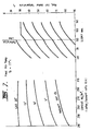
- the operator notes the ambient temperature from the control panel display, and follows the temperature curve to the point of intersection with the vertical axis corresponding to the amount of cement in the mix. This point is then projected horizontally to the reference line and the closest curve is followed to the point of intersection with the desired slump line, and the temperature is then selected from the right vertical axis. For example for an ambient temperature of 10°C, a cement control of 250 Kg/m3 and a desired slump of 70mm, the necessary temperature is 50°C.
- All programming switches have a tactile feel and together with the LCD display are mounted behind a washable plastic membrane.
- the computer used to control the system may comprise any suitable programmable microprocessor or may comprise a special purpose programmable microprocessor chip of any suitable type.
- the control system allows the following functions to be performed: the temperature of the water delivered to the tank may be selected and controlled on a load to load basis; the total volume of water required for a given load may be selected. This volume may be delivered in fractions of the total, if required; the temperature of the water in the hot water storage tank may be selected (to the nearest degree) up to maximum of 85 deg.
- Centrigrade the heat exchanger or boiler is controlled by the computer which allows the heater to be turned on and off at any given pre-set time for each day of operation. On any given day additional heating outside the pre-set time may be obtained, if desired, and the volume of water required in the tank is programmable and the tank kept filled to this volume at the selected temperature, if required.
- the size of the tank 1 and the capacity of the boiler 4 will be selected according to the size of the concrete batching plant. For example a small plant having an output of about 100 cubic meters per day will only require a 10,000 litre tank and a 400 MJ boiler while a large plant capable of continuous operation will require a 22,700 litre tank and a 1340 MJ boiler. Of course, if the requirement of a particular batching plant is that rapid recovery to the desired water temperature is required after an initial batch is prepared, a large boiler will be used. For example the 1340 MJ boiler is capable of heating about 7,000 litres to 60°C in one hour.
- Figs. 5A and 5B it will be noted that chemical accelerators require approximately 2 to 3 hours to accelerate the cement mix to a point where it is workable and the workable range before the mixture becomes unworkable is limited to about 2 hours, depending of course on the ambient temperature.
- Figs. 5A and 5B clearly show that the use of hot water at a temperature of 70°C in the cement mix accelerates curing to a stage where the cement is workable but as the mix cools the curing process slows so that the cement mix is workable over a considerably longer period.
- 5A and 5B shows that at an ambient temperature of 8°C, the hot water mix became workable after 1 hour, whereas the mix containing calcium chloride was not workable until near 3 hours had elapsed.
- the plain mix was unworkable over the full range tested.
- the ambient temperature was 22°C (Fig. 5B)
- the hot water mix became workable after about 15 minutes whereas the calcium chloride mix was not workable until about 2 hours had elapsed and the plain water mix was not workable until approximately 4 hours had elapsed.
- the workable range for the calcium chloride mix was approximately 2 hours whereas the hot water mix was workable for over 5 hours.
- the capital cost of a water heating system embodying the present invention may be recovered in a relatively short period of time.
- the capital recovery time from the savings achieved using the water heating system of the present invention would be less than 100 days.
- the capital recovery time may be further reduced by the use of flyash replacement in combination with the water heating system of the present invention.
- Fig. 7 shows a typical look up table which is used to calculate the required hot water temperature to achieve a final delivered water temperature, in the case of Fig. 7 accordance with the ambient temperature indicated at the left side of the graph and desired slump of the cement mix.
- the operator notes the ambient temperature from the control panel display, and follows the temperature curve to the point of intersection with the vertical axis corresponding to the amount of cement in the mix. This point is then projected horizontally to the reference line and the closest curve is followed to the point of intersection with the desired slump line, and the temperature is then selected from the right vertical axis. For example for an ambient temperature of 10°C, a cement control of 250 Kg/m3 and a desired slump of 70mm, the necessary temperature is 50°C.
- the computer 13 may be programmed with several look up tables providing the data necessary to achieve the most commonly desired final water temperatures, thereby requiring only the selection of the desired final mix temperature via the control panel, the computer calculating the necessary water temperature from the selected look-up table.
- the water heating system embodying the present invention provides significant advantages to the manufacturers of cement mixes, as well as to the builder. These advantages include: significant reduction of curing times: curing times which are predictably linear whereby the workable period of the concrete is adequate; enhancement of the existing cost advantages by the partial substitution of cement with flyash; the removal of the corrosion problems caused by the use of chloride chemical accelerators, and the reduction of "bleeding".
- the water heating system embodying the invention has the further general advantages of: low capital cost; low running cost; provision for selecting optimum water temperature; provision for using recycled water, and an efficiency which allows capital cost to be recouped in a short period of time.
- the low running cost of the system embodying the invention is achieved in part by the fact that the system heats only the amount of water required for a given concrete mixing batch. In the currently available water heating systems, large volumes of water are heated, with much of the hot water not subsequently being used.
- the size of the tank 1 and the capacity of the boiler 4 will be selected according to the size of the concrete batching plant. For example a small plant having an output of about 100 cubic meters per day will only require a 10,000 litre tank and a 400 MJ boiler while a large plant capable of continuous operation will require a 22,700 litre tank and a 1340 MJ boiler. Of course, if the requirement of a particular batching plant is that rapid recovery to the desired water temperature is required after an initial batch is prepared, a large boiler will be used. For example the 1340 MJ boiler is capable of heating about 7,000 litres to 60°C in one hour.
Landscapes
- Chemical & Material Sciences (AREA)
- Dispersion Chemistry (AREA)
- Preparation Of Clay, And Manufacture Of Mixtures Containing Clay Or Cement (AREA)
- On-Site Construction Work That Accompanies The Preparation And Application Of Concrete (AREA)
- Devices For Post-Treatments, Processing, Supply, Discharge, And Other Processes (AREA)
- Curing Cements, Concrete, And Artificial Stone (AREA)
Applications Claiming Priority (2)
| Application Number | Priority Date | Filing Date | Title |
|---|---|---|---|
| AU3762/87 | 1987-08-13 | ||
| AUPI376287 | 1987-08-13 |
Publications (2)
| Publication Number | Publication Date |
|---|---|
| EP0303554A2 true EP0303554A2 (de) | 1989-02-15 |
| EP0303554A3 EP0303554A3 (de) | 1991-03-20 |
Family
ID=3772388
Family Applications (1)
| Application Number | Title | Priority Date | Filing Date |
|---|---|---|---|
| EP19880630151 Withdrawn EP0303554A3 (de) | 1987-08-13 | 1988-08-11 | Heizsystem für Flüssigkeiten in einer Betonanlage |
Country Status (5)
| Country | Link |
|---|---|
| US (1) | US4915297A (de) |
| EP (1) | EP0303554A3 (de) |
| JP (1) | JPH01125206A (de) |
| CA (1) | CA1290322C (de) |
| NZ (1) | NZ225817A (de) |
Cited By (5)
| Publication number | Priority date | Publication date | Assignee | Title |
|---|---|---|---|---|
| DE4212606A1 (de) * | 1992-04-15 | 1993-10-21 | Koch Marmorit Gmbh | Verfahren und Vorrichtung zum Anrühren von Mörtel, Gipsputzen o. dgl. zur Verarbeitung auf Baustellen sowie Verwendung einer derartigen Vorrichtung |
| GB2333291A (en) * | 1998-01-14 | 1999-07-21 | Roger Longley | Making concrete; heating water |
| DE102013111846B3 (de) * | 2013-10-28 | 2015-01-08 | Elektro Schmaderer e.K. | System und Verfahren zur Flüssigkeitserwärmung für die Mischgutherstellung |
| EP2917009A4 (de) * | 2012-11-09 | 2016-08-17 | I B B Rheologie Inc | Verfahren und systeme unter verwendung von betonmischungstemperaturmessung |
| CN113048699A (zh) * | 2021-05-13 | 2021-06-29 | 中国水利水电第九工程局有限公司 | 高海拔寒冷地区大坝混凝土通水冷却工艺和装置 |
Families Citing this family (9)
| Publication number | Priority date | Publication date | Assignee | Title |
|---|---|---|---|---|
| KR100416790B1 (ko) * | 2001-02-01 | 2004-02-05 | 박군일 | 한중 및 서중 콘크리트의 제조를 위한 혼합수 공급시스템 |
| US7401742B2 (en) * | 2005-02-22 | 2008-07-22 | Dryair, Inc. | Fluid circulation apparatus for temporary heating |
| US8602316B2 (en) * | 2008-03-10 | 2013-12-10 | Robert G. Giannetti | Increased efficiency heating system method and apparatus for concrete production |
| US10781140B2 (en) | 2013-03-14 | 2020-09-22 | Solidia Technologies, Inc. | Method and apparatus for the curing of composite material by control over rate limiting steps in water removal |
| CN107206308B (zh) * | 2014-08-05 | 2021-06-25 | 索里迪亚科技公司 | 通过控制除水的速度限制步骤而固化复合材料的方法和设备 |
| CA2982740A1 (en) * | 2016-10-17 | 2018-04-17 | Electric Horsepower Inc. | Induction heater and vaporizer |
| US11402312B2 (en) * | 2018-02-08 | 2022-08-02 | Command Alkon Incorporated | Methods and systems for handling fresh concrete based on hydraulic pressure and on rheological probe pressure |
| CN111912746B (zh) * | 2020-06-09 | 2022-08-02 | 广西大学 | 基于底部阻力分析混凝土和易性的定量评估方法 |
| CN112303896B (zh) * | 2020-10-29 | 2021-11-02 | 常德湘雄建材有限公司 | 一种混凝土设备用车载水箱快速加热装置 |
Family Cites Families (10)
| Publication number | Priority date | Publication date | Assignee | Title |
|---|---|---|---|---|
| US2227349A (en) * | 1939-03-06 | 1940-12-31 | Clayton Manufacturing Co | Process and apparatus for generating steam |
| US2613653A (en) * | 1951-08-20 | 1952-10-14 | Wald Samuel | Fuel saving furnace |
| US3254839A (en) * | 1963-07-05 | 1966-06-07 | Ace Tank And Heater Company | Unitary heating system |
| US3357420A (en) * | 1965-09-08 | 1967-12-12 | Fleming Devices Inc | Combined sand and water heater |
| DE2225836A1 (de) * | 1972-05-26 | 1973-12-06 | Kaercher Fa Alfred | Dampferzeugungseinrichtung fuer eine betonherstellungsanlage |
| US4143814A (en) * | 1976-09-08 | 1979-03-13 | Ultimate Engineering Corporation | Control and transfer of energy |
| GB1574557A (en) * | 1978-05-04 | 1980-09-10 | Ritemixer Ltd | Truck mixers |
| AT391103B (de) * | 1981-11-20 | 1990-08-27 | Walter Dr Kallinger | Verfahren und anlage zur temperaturregelung bei der herstellung von baustoffmischungen |
| US4402190A (en) * | 1982-05-11 | 1983-09-06 | Reid Samuel I | Apparatus and method for heating and chilling concrete batch water |
| US4516720A (en) * | 1983-07-28 | 1985-05-14 | Chaplin James E | Automatic temperature adjustment apparatus |
-
1988
- 1988-08-11 EP EP19880630151 patent/EP0303554A3/de not_active Withdrawn
- 1988-08-12 JP JP63201819A patent/JPH01125206A/ja active Pending
- 1988-08-12 US US07/231,504 patent/US4915297A/en not_active Expired - Fee Related
- 1988-08-12 NZ NZ225817A patent/NZ225817A/xx unknown
- 1988-08-15 CA CA000574787A patent/CA1290322C/en not_active Expired - Lifetime
Cited By (7)
| Publication number | Priority date | Publication date | Assignee | Title |
|---|---|---|---|---|
| DE4212606A1 (de) * | 1992-04-15 | 1993-10-21 | Koch Marmorit Gmbh | Verfahren und Vorrichtung zum Anrühren von Mörtel, Gipsputzen o. dgl. zur Verarbeitung auf Baustellen sowie Verwendung einer derartigen Vorrichtung |
| GB2333291A (en) * | 1998-01-14 | 1999-07-21 | Roger Longley | Making concrete; heating water |
| GB2333291B (en) * | 1998-01-14 | 2002-04-17 | Roger Longley | Making concrete |
| EP2917009A4 (de) * | 2012-11-09 | 2016-08-17 | I B B Rheologie Inc | Verfahren und systeme unter verwendung von betonmischungstemperaturmessung |
| US10052794B2 (en) | 2012-11-09 | 2018-08-21 | Command Alkon Dutch Tech B.V. | Methods and systems using concrete mix temperature measurement |
| DE102013111846B3 (de) * | 2013-10-28 | 2015-01-08 | Elektro Schmaderer e.K. | System und Verfahren zur Flüssigkeitserwärmung für die Mischgutherstellung |
| CN113048699A (zh) * | 2021-05-13 | 2021-06-29 | 中国水利水电第九工程局有限公司 | 高海拔寒冷地区大坝混凝土通水冷却工艺和装置 |
Also Published As
| Publication number | Publication date |
|---|---|
| US4915297A (en) | 1990-04-10 |
| EP0303554A3 (de) | 1991-03-20 |
| NZ225817A (en) | 1990-09-26 |
| JPH01125206A (ja) | 1989-05-17 |
| CA1290322C (en) | 1991-10-08 |
Similar Documents
| Publication | Publication Date | Title |
|---|---|---|
| US4915297A (en) | Liquid heating system for concrete plants | |
| US6042258A (en) | Admixture dispensing and concrete mixer monitoring method | |
| US3625724A (en) | Cellular concrete and method for producing the same | |
| US5707179A (en) | Method and apparaatus for curing concrete | |
| US5289877A (en) | Cement mixing and pumping system and method for oil/gas well | |
| US6224250B1 (en) | Mobile cement additive and concrete admixture manufacturing process and system | |
| US4390371A (en) | Method for mixing, spraying and placing cementitious materials | |
| CN108625597A (zh) | 一种冬季混凝土施工方法 | |
| AU608351B2 (en) | Liquid heating system for concrete plants | |
| AU621765B2 (en) | Liquid heating system for concrete plants | |
| US5348764A (en) | Method for impregnating a lining material with a hardenable resin | |
| EP1384036A2 (de) | Verfahren und vorrichtung zur herstellung von flüssigeis | |
| CN202278658U (zh) | 无机发泡混凝土保温板加工设备 | |
| CN107859039A (zh) | 一种磨煤机基础大体积混凝土的温差控制及检测方法 | |
| JPWO1999062843A1 (ja) | ケミカルプレストレスコンクリート成形品の製造方法、およびその製造方法にも好適に用いられるコンクリート成形品の高温高圧水中養生装置、並びにこの養生装置を用いたコンクリート成形品の養生方法 | |
| CN102241066B (zh) | 一种用于住房墙体模块的工厂化生产方法 | |
| CN2436222Y (zh) | 用于液体混合搅拌的预混罐 | |
| US3540430A (en) | Snow disposal apparatus | |
| AU709941B2 (en) | System for determining free cement content | |
| JP4371282B2 (ja) | 生コン車のドラム内にセメント安定化剤を供給するための安定化剤自動計量供給装置 | |
| JPS6322863Y2 (de) | ||
| JPH0534892Y2 (de) | ||
| CN215157622U (zh) | 一种环氧砂浆运输储存装置 | |
| JP3023727B2 (ja) | コンクリート打設方法及び装置 | |
| JPH0620566Y2 (ja) | コンクリート製造装置 |
Legal Events
| Date | Code | Title | Description |
|---|---|---|---|
| PUAI | Public reference made under article 153(3) epc to a published international application that has entered the european phase |
Free format text: ORIGINAL CODE: 0009012 |
|
| AK | Designated contracting states |
Kind code of ref document: A2 Designated state(s): AT BE CH DE ES FR GB GR IT LI LU NL SE |
|
| PUAL | Search report despatched |
Free format text: ORIGINAL CODE: 0009013 |
|
| AK | Designated contracting states |
Kind code of ref document: A3 Designated state(s): AT BE CH DE ES FR GB GR IT LI LU NL SE |
|
| STAA | Information on the status of an ep patent application or granted ep patent |
Free format text: STATUS: THE APPLICATION IS DEEMED TO BE WITHDRAWN |
|
| 18D | Application deemed to be withdrawn |
Effective date: 19910921 |