EP0303378A2 - Pumpenvorrichtung einer Brennstoffeinspritzanlage - Google Patents
Pumpenvorrichtung einer Brennstoffeinspritzanlage Download PDFInfo
- Publication number
- EP0303378A2 EP0303378A2 EP88307066A EP88307066A EP0303378A2 EP 0303378 A2 EP0303378 A2 EP 0303378A2 EP 88307066 A EP88307066 A EP 88307066A EP 88307066 A EP88307066 A EP 88307066A EP 0303378 A2 EP0303378 A2 EP 0303378A2
- Authority
- EP
- European Patent Office
- Prior art keywords
- engine
- fuel
- lever
- pressure pump
- arm
- Prior art date
- Legal status (The legal status is an assumption and is not a legal conclusion. Google has not performed a legal analysis and makes no representation as to the accuracy of the status listed.)
- Withdrawn
Links
Images
Classifications
-
- F—MECHANICAL ENGINEERING; LIGHTING; HEATING; WEAPONS; BLASTING
- F02—COMBUSTION ENGINES; HOT-GAS OR COMBUSTION-PRODUCT ENGINE PLANTS
- F02M—SUPPLYING COMBUSTION ENGINES IN GENERAL WITH COMBUSTIBLE MIXTURES OR CONSTITUENTS THEREOF
- F02M59/00—Pumps specially adapted for fuel-injection and not provided for in groups F02M39/00 -F02M57/00, e.g. rotary cylinder-block type of pumps
- F02M59/44—Details, components parts, or accessories not provided for in, or of interest apart from, the apparatus of groups F02M59/02 - F02M59/42; Pumps having transducers, e.g. to measure displacement of pump rack or piston
- F02M59/447—Details, components parts, or accessories not provided for in, or of interest apart from, the apparatus of groups F02M59/02 - F02M59/42; Pumps having transducers, e.g. to measure displacement of pump rack or piston means specially adapted to limit fuel delivery or to supply excess of fuel temporarily, e.g. for starting of the engine
-
- F—MECHANICAL ENGINEERING; LIGHTING; HEATING; WEAPONS; BLASTING
- F02—COMBUSTION ENGINES; HOT-GAS OR COMBUSTION-PRODUCT ENGINE PLANTS
- F02D—CONTROLLING COMBUSTION ENGINES
- F02D1/00—Controlling fuel-injection pumps, e.g. of high pressure injection type
- F02D1/02—Controlling fuel-injection pumps, e.g. of high pressure injection type not restricted to adjustment of injection timing, e.g. varying amount of fuel delivered
- F02D1/04—Controlling fuel-injection pumps, e.g. of high pressure injection type not restricted to adjustment of injection timing, e.g. varying amount of fuel delivered by mechanical means dependent on engine speed, e.g. using centrifugal governors
-
- F—MECHANICAL ENGINEERING; LIGHTING; HEATING; WEAPONS; BLASTING
- F02—COMBUSTION ENGINES; HOT-GAS OR COMBUSTION-PRODUCT ENGINE PLANTS
- F02D—CONTROLLING COMBUSTION ENGINES
- F02D1/00—Controlling fuel-injection pumps, e.g. of high pressure injection type
- F02D1/02—Controlling fuel-injection pumps, e.g. of high pressure injection type not restricted to adjustment of injection timing, e.g. varying amount of fuel delivered
- F02D1/06—Controlling fuel-injection pumps, e.g. of high pressure injection type not restricted to adjustment of injection timing, e.g. varying amount of fuel delivered by means dependent on pressure of engine working fluid
- F02D1/065—Controlling fuel-injection pumps, e.g. of high pressure injection type not restricted to adjustment of injection timing, e.g. varying amount of fuel delivered by means dependent on pressure of engine working fluid of intake of air
-
- F—MECHANICAL ENGINEERING; LIGHTING; HEATING; WEAPONS; BLASTING
- F02—COMBUSTION ENGINES; HOT-GAS OR COMBUSTION-PRODUCT ENGINE PLANTS
- F02M—SUPPLYING COMBUSTION ENGINES IN GENERAL WITH COMBUSTIBLE MIXTURES OR CONSTITUENTS THEREOF
- F02M41/00—Fuel-injection apparatus with two or more injectors fed from a common pressure-source sequentially by means of a distributor
- F02M41/08—Fuel-injection apparatus with two or more injectors fed from a common pressure-source sequentially by means of a distributor the distributor and pumping elements being combined
- F02M41/14—Fuel-injection apparatus with two or more injectors fed from a common pressure-source sequentially by means of a distributor the distributor and pumping elements being combined rotary distributor supporting pump pistons
- F02M41/1405—Fuel-injection apparatus with two or more injectors fed from a common pressure-source sequentially by means of a distributor the distributor and pumping elements being combined rotary distributor supporting pump pistons pistons being disposed radially with respect to rotation axis
- F02M41/1411—Fuel-injection apparatus with two or more injectors fed from a common pressure-source sequentially by means of a distributor the distributor and pumping elements being combined rotary distributor supporting pump pistons pistons being disposed radially with respect to rotation axis characterised by means for varying fuel delivery or injection timing
Definitions
- This invention relates to a fuel injection pumping apparatus for supplying fuel to a compression ignition engine and of the kind comprising a high pressure pump operable in timed relationship with the engine, means including a low pressure pump for supplying fuel to the high pressure pump and a component forming part of the high pressure pump which is adjustable to determine the maximum amount of fuel which can be supplied by the high pressure pump.
- the high pressure pump comprises a plunger which is located within a transverse bore formed in a rotary distributor member which is driven in timed relationship with the associated engine.
- the plunger is moved outwardly by fuel supplied to the bore and inwardly to deliver fuel through an outlet to the associated engine, by a cam lobe formed on the internal peripheral surface of an annular cam.
- the aforesaid component comprises a stop ring which is angularly adjustable about the axis of rotation of the distributor member and which defines an internal stop surface which limits the outward movement of the plunger and thereby the amount of fuel which can flow into the bore for subsequent delivery to the associated engine.
- torque control means the modification of the maximum amount of fuel which can be supplied by the apparatus in accordance with the engine speed.
- torque control is to reduce the maximum amount of fuel which can be supplied by the apparatus as the engine speed approaches its allowed maximum value.
- other adjustments of the maximum fuel quantity may also be required in accordance with a varying engine operating parameter. For example in a turbo supercharged engine it is desirable to be able to adjust the fuel quantity in accordance with the air pressure in the engine air inlet manifold so that when the air pressure is low the maximum amount of fuel which can be supplied is reduced as compared with the situation when the turbo supercharger is in full operation. In another example it may be necessary to provide additional torque control in another part of the engine speed range.
- the object of the present invention is to provide an apparatus of the kind specified in a simple and convenient form.
- an apparatus of the kind specified comprises a three arm pivotal lever, the first and second arms being operatively connected to first and second engine operating parameter responsive devices which impart pivotal movement to the lever in response to a change in the engine operating parameter to which they are responsive, the third arm being connected to said component.
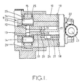
- the apparatus comprises a body part 10 in which is journalled a rotary cylindrical distributor member 11 in which is formed a transversely extending bore 12.
- the distributor member in use is driven in timed relationship with an associated engine, the distributor member for this purpose being coupled to a drive shaft shown.
- a pair of pumping plungers 13 Located in the bore is a pair of pumping plungers 13 at the outer ends of which are located cam followers each of which includes a roller 14.
- the rollers are engaged by cam lobes formed on the internal peripheral surface of an annular cam ring 15 which is located within the body part and which for the purpose of timing adjustment, may be angularly adjustable within the body part.
- the plungers and cam lobes form a high pressure pump 9.
- the longitudinal passage 16 communicates with a plurality of inlet passages 19 which are positioned to register in turn with an inlet port 20 formed in the body part and connected to the outlet 21 of a low pressure fuel supply pump 22 which has an inlet 23.
- the communication of the inlet port 20 with an inlet passage 19 occurs during the time when the plungers are allowed to move outwardly by the cam lobes and the quantity of fuel which is supplied to the bore during this period is controlled by a control device 24 which may for example be an adjustable throttle.
- a control device 24 which may for example be an adjustable throttle.
- a pair of stop rings 25 is provided, these being positioned on the opposite sides of the cam ring 15 and being mounted for angular adjustment within the body part.
- the internal surfaces of the stop rings are shaped to define stop surfaces for engagement by the rollers during outward movement of the plungers. The extent of outward movement of the plungers and therefore the maximum amount of fuel which can be supplied to the associated engine is determined by the angular setting of the stop rings.
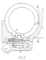
- the stop rings are connected together so that they move angularly in unison, by means of a saddle member 26 which, as shown in Figure 2, includes a base section 27 upstanding from which are a pair of spaced tongues 28 which engage within slots 29 respectively formed in the stop rings 25.
- the saddle member is located on one side of a support plate 30 which is secured within the body part and which is provided with a slot 31.
- a support plate 30 On the opposite side of the support plate 30 is a generally U-shaped member 32, the U-shaped member and the base section of the saddle member being secured together by rivets 33, there being located about each rivet, spacers 34 which slide in the slot 31.
- One limb 35 of the U-shaped member is provided with an aperture through which extends a spring locating rod 36 the rod being carried on a support 37 secured within the body part.
- a spring 38 Interposed between the support 37 and the limb 35 is a spring 38 the effect of which is to bias the saddle member and therefore the stop rings, towards a position to reduce the maximum amount of fuel which can be supplied to the associated engine.
- a stop means 39 is provided for engagement with the other limb 40 of the member 32 to determine the movement of the saddle member under the action of the spring 38 and the stop means forms part of a device responsive to an engine operating parameter and which will be explained.
- a pin 42 movable in a slot 43 is provided the pin being biased by means of a spring which is stronger than the spring 38.
- a fluid pressure operable piston (not shown) responsive to the outlet pressure of the low pressure pump 22 and which moves the pin against the action of the spring to allow the stop plates to move to the normal maximum fuel position as determined by the stop 39.
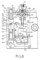
- the stop means 39 is seen to be one end of the one arm of a three armed lever 44 which carries a pivot pin 45 slidable in an elongated slot 46 in the support plate 30.
- the lever 44 is of "T" shaped form and the two other arms 47, 48 are of equal length and each terminate in an upstanding tang.
- the arm 47 its tang extends within a transverse opening formed in a piston 49 located within a cylinder 50.
- the piston forms part of a first engine operating parameter responsive device 49A.
- the ends of the cylinder are closed by plugs 51, 52, the plug 51 forming an abutment for a spring 54 interposed between the plug and a flanged tubular abutment against which bears a further spring 53 the other end of which engages the piston 49.
- a pin 55 is fixed in a bore in the piston and terminates in a spherical end in the opening therein.
- the pin external of the piston defines an enlarged portion about which is located the spring 53 and a reduced portion which guides the adjacent end of the tubular abutment and the spring 54.
- the plug 52 is formed in two parts the outer part 56 forming an adjustable stop for the piston 49 and the inner part 57 forming an adjustable abutment for a coiled spring 58 which acts on the piston in opposition to the springs 53, 54.
- a passage (not shown) is provided to allow fuel under pressure from the outlet of the supply pump 22 to act on the face of the piston 49 engaged by the spring 58.
- the tang on the arm 48 of the lever 44 is engaged by the spherical end of a push rod 59 which is operatively connected to a pressure responsive device 60 which includes an inlet 61.
- the inlet 61 is an air inlet which in use, is connected to the air inlet manifold of the associated engine which in this case is a turbo supercharged engine.
- the device includes a diaphragm 62 of annular form the outer peripheral rim of which is trapped between two parts of the housing of the apparatus.
- the inner peripheral rim of the diaphragm is sealed to a resiliently loaded carrier 63 which when the pressure of air in the inlet increases, urges the push rod 59 downwardly as seen in the drawing.
- Figures 2 and 3 show the parts in the position which they adopt for the purpose of excess fuel supply.
- the axes of movement of the pin 55 and the rod 59 are parallel to each other and to the slot 46, the slot being disposed midway between said axes.
- the piston 49 In operation, and ignoring for the moment the pressure responsive device 60, with an increase in the output pressure of the low pressure pump and when the preloading of the springs 53, 54 is overcome, the piston 49 will move and allow anti-clockwise movement of the lever 44 under the action of the spring 38. This allows the spring 38 to move the stop plates to reduce the maximum amount of fuel which can be supplied to the engine thereby providing torque control.
- the spring 58 and the inner part 57 of the plug 52 are provided for the purpose of adjusting the fuel pressure and therefore the engine speed, at which the piston 49 starts to move.
- the pin 45 slides along the slot 46 and the lever pivots about the spherical end of the push rod 59.
- the pressure responsive device may be replaced by a fuel pressure responsive device which modifies the maximum fuel quantity at a lower engine speed. It is also possible to reverse the piston 49 and the associated springs in the cylinder 50.
Landscapes
- Engineering & Computer Science (AREA)
- Chemical & Material Sciences (AREA)
- Combustion & Propulsion (AREA)
- Mechanical Engineering (AREA)
- General Engineering & Computer Science (AREA)
- High-Pressure Fuel Injection Pump Control (AREA)
- Fuel-Injection Apparatus (AREA)
Applications Claiming Priority (2)
| Application Number | Priority Date | Filing Date | Title |
|---|---|---|---|
| GB8718853 | 1987-08-08 | ||
| GB878718853A GB8718853D0 (en) | 1987-08-08 | 1987-08-08 | Fuel injection pumping apparatus |
Publications (2)
| Publication Number | Publication Date |
|---|---|
| EP0303378A2 true EP0303378A2 (de) | 1989-02-15 |
| EP0303378A3 EP0303378A3 (de) | 1989-07-19 |
Family
ID=10622042
Family Applications (1)
| Application Number | Title | Priority Date | Filing Date |
|---|---|---|---|
| EP88307066A Withdrawn EP0303378A3 (de) | 1987-08-08 | 1988-08-01 | Pumpenvorrichtung einer Brennstoffeinspritzanlage |
Country Status (4)
| Country | Link |
|---|---|
| US (1) | US4903661A (de) |
| EP (1) | EP0303378A3 (de) |
| JP (1) | JPH01187362A (de) |
| GB (1) | GB8718853D0 (de) |
Families Citing this family (2)
| Publication number | Priority date | Publication date | Assignee | Title |
|---|---|---|---|---|
| US5957101A (en) * | 1997-07-09 | 1999-09-28 | Kohler Co. | Automatic compression release mechanism for an internal combustion engine |
| DE102013204327A1 (de) * | 2013-03-13 | 2014-09-18 | Robert Bosch Gmbh | Zylinderkopfrohteil, Zylinderkopf und Hochdruckpumpe für Brennstoffeinspritzanlagen |
Family Cites Families (11)
| Publication number | Priority date | Publication date | Assignee | Title |
|---|---|---|---|---|
| GB482864A (en) * | 1936-08-24 | 1938-04-06 | Saurer Ag Adolph | Improvements in and relating to the control of the fuel supply to internal combustion engines |
| FR2278928A1 (fr) * | 1973-10-30 | 1976-02-13 | Sigma Diesel | Perfectionnements aux dispositifs de commande du debit de combustible pour moteurs a combustion interne |
| DE2526148C2 (de) * | 1975-06-12 | 1983-08-25 | Robert Bosch Gmbh, 7000 Stuttgart | Regeleinrichtung für die Kraftstoffzufuhr von Einspritzbrennkraftmaschinen |
| US4120275A (en) * | 1975-06-28 | 1978-10-17 | Diesel Kiki Co., Ltd. | Engine fuel injection pump governor |
| DE2747083A1 (de) * | 1977-10-20 | 1979-05-03 | Bosch Gmbh Robert | Vorrichtung zur begrenzung der vollasteinspritzmenge bei einer aufgeladenen luftverdichtenden einspritzbrennkraftmaschine |
| DE2847572C2 (de) * | 1978-11-02 | 1986-07-10 | Robert Bosch Gmbh, 7000 Stuttgart | Verteilerkraftstoffeinspritzpumpe für aufgeladene Dieselmotoren |
| DE2849093C2 (de) * | 1978-11-11 | 1987-01-22 | Klöckner-Humboldt-Deutz AG, 5000 Köln | Mechanischer Drehzahlregler für eine Einspritzpumpe |
| GB2061402B (en) * | 1979-10-20 | 1983-09-28 | Lucas Industries Ltd | Fuel injection pump |
| GB2070134B (en) * | 1980-02-14 | 1983-08-17 | Lucas Industries Ltd | Liquid fuel injection pumping apparatus |
| US4493617A (en) * | 1983-03-04 | 1985-01-15 | Stanadyne, Inc. | Fuel injection pump with plunger stroke control |
| DE3430141A1 (de) * | 1984-08-16 | 1986-02-27 | Robert Bosch Gmbh, 7000 Stuttgart | Kraftstoffeinspritzanlage fuer diesel-brennkraftmaschinen, insbesondere fuer fahrzeug-dieselmotoren |
-
1987
- 1987-08-08 GB GB878718853A patent/GB8718853D0/en active Pending
-
1988
- 1988-08-01 EP EP88307066A patent/EP0303378A3/de not_active Withdrawn
- 1988-08-03 US US07/227,655 patent/US4903661A/en not_active Expired - Fee Related
- 1988-08-08 JP JP63196208A patent/JPH01187362A/ja active Pending
Also Published As
| Publication number | Publication date |
|---|---|
| EP0303378A3 (de) | 1989-07-19 |
| US4903661A (en) | 1990-02-27 |
| JPH01187362A (ja) | 1989-07-26 |
| GB8718853D0 (en) | 1987-09-16 |
Similar Documents
| Publication | Publication Date | Title |
|---|---|---|
| US4292012A (en) | Liquid fuel injection pumping apparatus | |
| US4098249A (en) | Fuel injection pumping apparatus | |
| US4074667A (en) | Liquid fuel injection pumping apparatus | |
| US4214564A (en) | Fuel injection pumping apparatus | |
| US4903661A (en) | Fuel injection pumping apparatus | |
| US4358255A (en) | Liquid fuel injection pumping apparatus | |
| US4299542A (en) | Fuel injection pumping apparatus | |
| US4359995A (en) | Fuel injection pumping apparatus | |
| US4055387A (en) | Liquid fuel injection pumping apparatus | |
| EP0118385B1 (de) | Kraftstoffeinspritzpumpe mit Kolbenhubsteuerung | |
| US4050437A (en) | Liquid fuel injection pumping apparatus | |
| US3913546A (en) | Horsepower limiter and overfueling control mechanism | |
| US4358256A (en) | Fuel injection pumping apparatus | |
| US4362140A (en) | Liquid fuel injection pumps | |
| GB2068591A (en) | Fuel Injection Pumping Apparatus | |
| CA1047339A (en) | Liquid fuel injection pumping apparatus for internal combustion engines | |
| US4441474A (en) | Fuel injection pumping apparatus | |
| US2815741A (en) | Timing apparatus for fuel injection pump | |
| US4320733A (en) | Fuel pumping apparatus | |
| US4751903A (en) | Fuel pumping apparatus | |
| US4348995A (en) | Fuel pumping apparatus | |
| GB1569265A (en) | Fuel injection pumping apparatus | |
| US4930998A (en) | Fuel pump | |
| US3937199A (en) | Fuel injection pump | |
| GB2046349A (en) | Liquid fuel injection pumping apparatus |
Legal Events
| Date | Code | Title | Description |
|---|---|---|---|
| PUAI | Public reference made under article 153(3) epc to a published international application that has entered the european phase |
Free format text: ORIGINAL CODE: 0009012 |
|
| AK | Designated contracting states |
Kind code of ref document: A2 Designated state(s): DE ES FR GB IT |
|
| PUAL | Search report despatched |
Free format text: ORIGINAL CODE: 0009013 |
|
| AK | Designated contracting states |
Kind code of ref document: A3 Designated state(s): DE ES FR GB IT |
|
| 17P | Request for examination filed |
Effective date: 19891124 |
|
| 17Q | First examination report despatched |
Effective date: 19910220 |
|
| STAA | Information on the status of an ep patent application or granted ep patent |
Free format text: STATUS: THE APPLICATION IS DEEMED TO BE WITHDRAWN |
|
| 18D | Application deemed to be withdrawn |
Effective date: 19910703 |