EP0303208A2 - Device for closing the gap between the ends of an intaglio plate attached to a form cylinder - Google Patents
Device for closing the gap between the ends of an intaglio plate attached to a form cylinder Download PDFInfo
- Publication number
- EP0303208A2 EP0303208A2 EP88112836A EP88112836A EP0303208A2 EP 0303208 A2 EP0303208 A2 EP 0303208A2 EP 88112836 A EP88112836 A EP 88112836A EP 88112836 A EP88112836 A EP 88112836A EP 0303208 A2 EP0303208 A2 EP 0303208A2
- Authority
- EP
- European Patent Office
- Prior art keywords
- gap
- forme cylinder
- plate
- closing
- pressure bars
- Prior art date
- Legal status (The legal status is an assumption and is not a legal conclusion. Google has not performed a legal analysis and makes no representation as to the accuracy of the status listed.)
- Granted
Links
Images

Classifications
-
- B—PERFORMING OPERATIONS; TRANSPORTING
- B41—PRINTING; LINING MACHINES; TYPEWRITERS; STAMPS
- B41F—PRINTING MACHINES OR PRESSES
- B41F27/00—Devices for attaching printing elements or formes to supports
- B41F27/12—Devices for attaching printing elements or formes to supports for attaching flexible printing formes
- B41F27/1293—Devices for filling up the cylinder gap; Devices for removing the filler
Definitions
- the invention relates to a device for closing the gap between the ends of a gravure plate clamped on a forme cylinder, with a plate covering the gap and devices for filling the gap cavity with plastic and hardenable material, consisting of two shaped pieces - which are inserted onto the shaft ends of the forme cylinder -, A profile firmly connected to the fittings, in which two movable pressure strips are incorporated.
- This object is achieved in that a plurality of pressure screws distributed over the length of the pressure bars are arranged above the pressure bars.
- the forme cylinder 1 of a sheet-fed or rotary rotogravure printing machine is provided with a groove 2 which runs along the forme cylinder axis and widens from the cylinder surface to the cylinder center, into which the intaglio printing plate 3 with the two is clamped folded ends 4 is hooked at an acute angle.
- a plate 6 is placed over the two end sections of the intaglio printing plate, which is elastically bendable or shaped according to the contour of the cylinder surface.
- the device according to the invention is used to press the plate, the construction of which is described below.
Landscapes
- Manufacture Or Reproduction Of Printing Formes (AREA)
- Supply, Installation And Extraction Of Printed Sheets Or Plates (AREA)
- Printing Plates And Materials Therefor (AREA)
- Rotary Presses (AREA)
Abstract
Vorrichtung zum Verschließen des Spaltes zwischen den Enden einer auf einen Formzylinder (1) aufgespannten Tiefdruckplatte (3), mit einer den Spalt (5) abdeckenden Platte (6) und Einrichtungen zum Füllen des Spalthohlraums mit plastischem und aushärtbarem Material, bestehend aus zwei Formstücken (7) - die auf die Wellenenden des Formzylinders eingesetzt werden -, und einem mit den Formstücken fest verbundenen Profil (8), in das zwei bewegbare Andrückleisten (9) eingearbeitet sind, wobei über den Andrückleisten jeweils mehrere über die Länge der Andrückleisten verteilte Andrückschrauben (10) angeordnet sind. 
Description
Die Erfindung betrifft eine Vorrichtung zum Verschließen des Spaltes zwischen den Enden einer auf einen Formzylinder aufgespannten Tiefdruckplatte, mit einer den Spalt abdeckenden Platte und Einrichtungen zum Füllen des Spalthohlraums mit plastischem und aushärtbarem Material, bestehend aus zwei Formstücken - die auf die Wellenenden des Formzylinders eingesetzt werden -, einem mit den Formstücken fest verbundenen Profil, in das zwei bewegbare Andrückleisten eingearbeitet sind.The invention relates to a device for closing the gap between the ends of a gravure plate clamped on a forme cylinder, with a plate covering the gap and devices for filling the gap cavity with plastic and hardenable material, consisting of two shaped pieces - which are inserted onto the shaft ends of the forme cylinder -, A profile firmly connected to the fittings, in which two movable pressure strips are incorporated.
Es ist bekannt, Tiefdruckplatten, bestehend aus einem dimensionsstabilen und biegsamen Träger und einer darauf aufgebrachten Deckschicht, auf einen Formzylinder einer Bogen- oder Rotationsdruckmaschine aufzuspannen. Hierzu ist der Formzylinder mit einer parallel oder auch schräg zur Formzylinderachse verlaufenden Nut versehen, in die die Tiefdruckplatte mit umgekanteten Enden unter spitzem Winkel eingehängt und festgehalten wird. Der dabei entstehende Spalt zwischen den beiden Enden der Tiefdruckplatte wird mit einer Kunststoffmasse verschlossen. Dazu wird eine fließfähige und aushärtbare Masse in den Spalt gefüllt, nachdem zuvor dieser durch ein Flächenstück, beispielsweise eine den Spalt abdeckende Platte mittels eines Druckstücks abgedeckt wurde (s. DE-A 3 08 807).It is known to clamp gravure printing plates, consisting of a dimensionally stable and flexible support and a cover layer applied thereon, onto a forme cylinder of a sheet-fed or rotary printing machine. For this purpose, the forme cylinder is provided with a groove running parallel or also obliquely to the forme cylinder axis, into which the intaglio printing plate is hung and held at an acute angle with bent ends. The resulting gap between the two ends of the rotogravure plate is closed with a plastic compound. For this purpose, a flowable and curable mass is filled into the gap after it has been covered beforehand by a flat piece, for example a plate covering the gap, by means of a pressure piece (see DE-A 3 08 807).
Bei der Weiterentwicklung obiger Vorrichtungen wurde das Druckstück durch zwei Biegelineale ersetzt, wobei dieselben extrem biegesteif ausgeführt sein müssen, um ein teilweises Abheben der Biegeleisten beim Einspritzen der Kunststoffmasse zu verhindern. Dies hat zur Folge, daß unter der Platte Kunststoffmasse herausgedrückt wird (s. DE-A 34 01 501).In the further development of the above devices, the pressure piece was replaced by two bending rulers, the same having to be designed to be extremely rigid in order to prevent the bending strips from being partially lifted when the plastic compound was injected. This has the consequence that plastic mass is pressed out from under the plate (see DE-A 34 01 501).
All die vorgenannten Vorrichtungen sind mit dem Nachteil behaftet, daß dieselben sehr schwer sind und zudem schwer zu handhaben sind. Des weiteren ist die Umstellung auf verschiedene Zylinderdurchmesser mit diesen Vorrichtungen nicht flexibel genug. Letztendlich konnte auch mit den oben erwähnten Biegelinealen eine Durchbiegung derselben beim Einspritzen der Kunststoffmasse nicht verhindert werden.All of the above devices have the disadvantage that they are very heavy and also difficult to handle. Furthermore, the conversion to different cylinder diameters is not flexible enough with these devices. Ultimately, even with the above-mentioned bending rulers, it was not possible to prevent them from deflecting when the plastic compound was injected.
Es stellte sich daher die Aufgabe, eine Vorrichtung zum Verschließen des Spaltes zwischen den Enden einer auf einen Formzylinder aufgespannten Tiefdruckplatte zu entwickeln, die ein deutlich geringeres Gewicht aufweist, so daß dieselbe bei kleineren Druckeinheiten von einer Person ge handhabt werden kann. Des weiteren sollte der Spaltverschluß auf dem Formzylindertransportwagen oder in der Druckmaschine selbst vorgenommen werden können, und eine Durchbiegung der Biegelineale ausgeschlossen werden.It was therefore the task of developing a device for closing the gap between the ends of a gravure plate clamped on a forme cylinder, which has a significantly lower weight, so that the same ge in smaller printing units by one person can be handled. Furthermore, it should be possible to close the gap on the forme cylinder transport carriage or in the printing press itself, and to prevent deflection of the bending rulers.
Diese Aufgabe wird erfindungsgemäß dadurch gelöst, daß über den Andruckleisten jeweils mehrere über die Länge der Andrückleisten verteilte Andrückschrauben angeordnet sind.This object is achieved in that a plurality of pressure screws distributed over the length of the pressure bars are arranged above the pressure bars.
Zum besseren Verständnis der Erfindung ist ein Ausführungsbeispiel anhand der Zeichnung nachfolgend beschrieben:For a better understanding of the invention, an embodiment is described below with reference to the drawing:
Es zeigen
- Figur 1 den Formzylinder mit aufgespannter Tiefdruckplatte und der erfindungsgemäßen Vorrichtung zum Verschließen des Spaltes im Querschnitt,
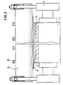
Figur 2 den Formzylinder wie Figur 1, jedoch im Längsschnitt.
- FIG. 1 the cross-section of the forme cylinder with a rotogravure plate and the device according to the invention for closing the gap,
- Figure 2 shows the forme cylinder as Figure 1, but in longitudinal section.
Der Formzylinder 1 einer Bogen- oder Rotationstiefdruckmaschine ist, wie in Figur 1 und 2 zu sehen, mit einer entlang der Formzylinderachse verlaufenden und von der Zylinderoberfläche zum Zylinderzentrum hin sich aufweitenden Nut 2 versehen, in die die auf dem Formzylinder aufgespannte Tiefdruckplatte 3 mit den beiden umgekanteten Enden 4 unter spitzem Winkel eingehängt ist. Zum Verschließen des Spaltes 5 zwischen den beiden Enden wird eine die beiden Endabschnitte der Tiefdruckplatte übergreifende Platte 6 aufgelegt, die elastisch biegbar oder entsprechend der Kontur der Zylinderoberfläche geformt ist. Zum Andrücken der Platte wird die erfindungsgemäße Vorrichtung verwendet, deren Aufbau nachstehend beschrieben wird.As can be seen in FIGS. 1 and 2, the forme cylinder 1 of a sheet-fed or rotary rotogravure printing machine is provided with a
Zwischen den zwei Formstücken 7, die in die Wellenenden des Formzylinders eingesetzt sind, befindet sich ein mit dem Formstück fest verbundenes Profil 8, in welches bewegbar angeordnete Andrückleisten 9 eingearbeitet sind, die in Richtung Formzylinder verstellbar sind. Zusätzlich sind in diese Profile - mit den Andrückleisten fluchtend - mehrere Andrückschrauben 10 eingearbeitet, mittels deren die Andrückleisten auf ihrer gesamten Länge mit hoher Kraft gegen die Platte angedrückt werden können, so daß auf der gesamten Länge des Zylinders beidseitig des Spaltes Kontakt zwischen Platte und Tiefdruckplatte besteht. Dadurch wird erreicht, daß beim Einspritzen der Kunststoffmasse dieselbe nicht zwischen fehlenden Kontaktstellen zwischen Platte und Tiefdruckplatte herausfließen kann.Between the two shaped pieces 7, which are inserted into the shaft ends of the forme cylinder, there is a
Claims (1)
Applications Claiming Priority (2)
| Application Number | Priority Date | Filing Date | Title |
|---|---|---|---|
| DE3727115 | 1987-08-14 | ||
| DE19873727115 DE3727115A1 (en) | 1987-08-14 | 1987-08-14 | DEVICE FOR CLOSING THE GAP BETWEEN THE ENDS OF A PRINTING PLATE CLAMPED ON A FORM CYLINDER |
Publications (3)
| Publication Number | Publication Date |
|---|---|
| EP0303208A2 true EP0303208A2 (en) | 1989-02-15 |
| EP0303208A3 EP0303208A3 (en) | 1989-11-23 |
| EP0303208B1 EP0303208B1 (en) | 1992-03-11 |
Family
ID=6333746
Family Applications (1)
| Application Number | Title | Priority Date | Filing Date |
|---|---|---|---|
| EP88112836A Expired - Lifetime EP0303208B1 (en) | 1987-08-14 | 1988-08-06 | Device for closing the gap between the ends of an intaglio plate attached to a form cylinder |
Country Status (6)
| Country | Link |
|---|---|
| US (1) | US4896603A (en) |
| EP (1) | EP0303208B1 (en) |
| JP (1) | JPS6469347A (en) |
| CA (1) | CA1306640C (en) |
| DE (2) | DE3727115A1 (en) |
| ES (1) | ES2029502T3 (en) |
Families Citing this family (5)
| Publication number | Priority date | Publication date | Assignee | Title |
|---|---|---|---|---|
| DE4102858A1 (en) * | 1990-03-08 | 1991-09-12 | Heidelberger Druckmasch Ag | PRINTING CYLINDERS FOR ROTARY PRINTING MACHINES |
| JP3878622B2 (en) * | 2004-05-19 | 2007-02-07 | 株式会社東京機械製作所 | Blanket cylinder filling material |
| US20060054328A1 (en) * | 2004-09-16 | 2006-03-16 | Chevron U.S.A. Inc. | Process of installing compliant offshore platforms for the production of hydrocarbons |
| CN100417521C (en) * | 2005-02-23 | 2008-09-10 | 吴广顺 | Inclined open technology of single sheet paper gravure machie printing plate rotary drum and flat sheet type gravure technology |
| WO2021193423A1 (en) * | 2020-03-23 | 2021-09-30 | 東レ株式会社 | Cylindrical printing plate and method for manufacturing printed matter |
Family Cites Families (5)
| Publication number | Priority date | Publication date | Assignee | Title |
|---|---|---|---|---|
| FR2527520A1 (en) * | 1982-05-27 | 1983-12-02 | Cuir Jean Pierre | DEVICE FOR FIXING A PLATE ON A CYLINDER |
| DK159251C (en) * | 1983-03-12 | 1991-02-18 | Basf Ag | PROCEDURE FOR CLOSING THE SPACE BETWEEN A END OF THE PRESSURE PRESSURE CYLINDER OPENING THE END OF THE PRESSURE PRESSURE Cylinder, AND THE FITTING OF THE DEPTH PRESSURE DEVICE |
| DE3401501A1 (en) * | 1984-01-18 | 1985-07-25 | Basf Ag, 6700 Ludwigshafen | DEVICE FOR CLOSING THE GAP BETWEEN THE ENDS OF A PRINTING PLATE CLAMPED ON A FORM CYLINDER |
| DE3433046A1 (en) * | 1984-09-08 | 1986-03-20 | Basf Ag, 6700 Ludwigshafen | METHOD FOR CLOSING THE GAP BETWEEN THE ENDS OF PRINTING PLATES CLAMPED ON FORM CYLINDERS |
| EP0211450B1 (en) * | 1985-07-26 | 1989-05-24 | De La Rue Giori S.A. | Method and installation for fixing a printing plate on a printing cylinder |
-
1987
- 1987-08-14 DE DE19873727115 patent/DE3727115A1/en not_active Withdrawn
-
1988
- 1988-08-06 ES ES198888112836T patent/ES2029502T3/en not_active Expired - Lifetime
- 1988-08-06 EP EP88112836A patent/EP0303208B1/en not_active Expired - Lifetime
- 1988-08-06 DE DE8888112836T patent/DE3869013D1/en not_active Expired - Lifetime
- 1988-08-10 CA CA000574359A patent/CA1306640C/en not_active Expired - Lifetime
- 1988-08-12 JP JP63200260A patent/JPS6469347A/en active Pending
- 1988-08-12 US US07/231,276 patent/US4896603A/en not_active Expired - Fee Related
Also Published As
| Publication number | Publication date |
|---|---|
| EP0303208B1 (en) | 1992-03-11 |
| JPS6469347A (en) | 1989-03-15 |
| DE3727115A1 (en) | 1989-02-23 |
| CA1306640C (en) | 1992-08-25 |
| US4896603A (en) | 1990-01-30 |
| ES2029502T3 (en) | 1992-08-16 |
| EP0303208A3 (en) | 1989-11-23 |
| DE3869013D1 (en) | 1992-04-16 |
Similar Documents
| Publication | Publication Date | Title |
|---|---|---|
| EP0238804B1 (en) | Device for attaching flexible printing forms to the plate cylinder of a rotary printing machine | |
| EP0132532B1 (en) | Cylinder for a rotary printing machine | |
| EP0359959A2 (en) | Duct blade inking device | |
| DE2443158A1 (en) | METHOD AND DEVICE FOR DETERMINING THE SHEARING STRESS IN POWDERY AND / OR GRAINY MATERIAL | |
| EP0303208B1 (en) | Device for closing the gap between the ends of an intaglio plate attached to a form cylinder | |
| DE1561018B1 (en) | Clamping device for attaching a sheet-like part, for example a printing blanket, to a printing machine cylinder | |
| DE2505235C2 (en) | Saddle plate for attaching pressure plates to rotary high pressure machines | |
| EP1545880B1 (en) | Clamping device for clamping a flexible covering of a cylinder of a printing press | |
| EP0151397B1 (en) | Device for closing the gap between the ends of an intaglio plate attached to a forme cylinder | |
| DE2606223A1 (en) | DEVICE FOR TENSIONING THE RUBBER CLOTH OF AN OFFSET PRINTING MACHINE | |
| EP1530514B1 (en) | Method for mounting packing onto the cylinder of a printing press | |
| DE2723845A1 (en) | DEVICE FOR POSITIONING A COLOR MEASURING DEVICE ON AN INK BOX ROLLER | |
| DE4123431A1 (en) | Tensioner for silk screen printing stencil - is cylinder-piston unit fixed to base component and operated by pressure medium | |
| DE3813777C2 (en) | ||
| DE19500128B4 (en) | Ferrule for construction | |
| DE68904634T2 (en) | DEVICE FOR BENDING A SHEET EDGE. | |
| DE1922749B2 (en) | Device for fastening a printing plate on the forme cylinder of a printing machine | |
| DE2418458B2 (en) | Device for attaching sealing strips to guide plates of a conveyor belt, which are used to guide the material | |
| DE69104764T2 (en) | Device and method for mounting a pressure plate on a narrow-gap cylinder. | |
| DE2809522C3 (en) | Blanket tensioning device of a transfer cylinder of a sheet-fed rotary offset printing machine | |
| DE3434670A1 (en) | DEVICE FOR COVERING A FORM CYLINDER WITH A WRAPPING PLATE | |
| DE102006006331B3 (en) | Fixing device to attach lifter to cylinder has printing-plate front end at right angle or acute angle for hanging in correspondingly aligned channel | |
| DE8709029U1 (en) | Device for applying a substance to a web | |
| DE2156892C3 (en) | Braking device for the drawing head of a drawing machine | |
| DE10244945A1 (en) | Clamping device to fix flexible clothing on printing cylinder has at least one rotating clamping body and pressing device |
Legal Events
| Date | Code | Title | Description |
|---|---|---|---|
| PUAI | Public reference made under article 153(3) epc to a published international application that has entered the european phase |
Free format text: ORIGINAL CODE: 0009012 |
|
| AK | Designated contracting states |
Kind code of ref document: A2 Designated state(s): BE CH DE ES FR GB IT LI NL |
|
| PUAL | Search report despatched |
Free format text: ORIGINAL CODE: 0009013 |
|
| AK | Designated contracting states |
Kind code of ref document: A3 Designated state(s): BE CH DE ES FR GB IT LI NL |
|
| 17P | Request for examination filed |
Effective date: 19891021 |
|
| 17Q | First examination report despatched |
Effective date: 19910508 |
|
| GRAA | (expected) grant |
Free format text: ORIGINAL CODE: 0009210 |
|
| AK | Designated contracting states |
Kind code of ref document: B1 Designated state(s): BE CH DE ES FR GB IT LI NL |
|
| ITF | It: translation for a ep patent filed | ||
| REF | Corresponds to: |
Ref document number: 3869013 Country of ref document: DE Date of ref document: 19920416 |
|
| GBT | Gb: translation of ep patent filed (gb section 77(6)(a)/1977) | ||
| PGFP | Annual fee paid to national office [announced via postgrant information from national office to epo] |
Ref country code: FR Payment date: 19920714 Year of fee payment: 5 |
|
| PGFP | Annual fee paid to national office [announced via postgrant information from national office to epo] |
Ref country code: CH Payment date: 19920715 Year of fee payment: 5 |
|
| ET | Fr: translation filed | ||
| PGFP | Annual fee paid to national office [announced via postgrant information from national office to epo] |
Ref country code: GB Payment date: 19920731 Year of fee payment: 5 |
|
| PGFP | Annual fee paid to national office [announced via postgrant information from national office to epo] |
Ref country code: ES Payment date: 19920811 Year of fee payment: 5 |
|
| PGFP | Annual fee paid to national office [announced via postgrant information from national office to epo] |
Ref country code: DE Payment date: 19920812 Year of fee payment: 5 |
|
| REG | Reference to a national code |
Ref country code: ES Ref legal event code: FG2A Ref document number: 2029502 Country of ref document: ES Kind code of ref document: T3 |
|
| PGFP | Annual fee paid to national office [announced via postgrant information from national office to epo] |
Ref country code: NL Payment date: 19920831 Year of fee payment: 5 |
|
| PGFP | Annual fee paid to national office [announced via postgrant information from national office to epo] |
Ref country code: BE Payment date: 19920903 Year of fee payment: 5 |
|
| PLBE | No opposition filed within time limit |
Free format text: ORIGINAL CODE: 0009261 |
|
| STAA | Information on the status of an ep patent application or granted ep patent |
Free format text: STATUS: NO OPPOSITION FILED WITHIN TIME LIMIT |
|
| 26N | No opposition filed | ||
| PG25 | Lapsed in a contracting state [announced via postgrant information from national office to epo] |
Ref country code: GB Effective date: 19930806 |
|
| PG25 | Lapsed in a contracting state [announced via postgrant information from national office to epo] |
Ref country code: ES Free format text: LAPSE BECAUSE OF THE APPLICANT RENOUNCES Effective date: 19930807 |
|
| PG25 | Lapsed in a contracting state [announced via postgrant information from national office to epo] |
Ref country code: LI Effective date: 19930831 Ref country code: CH Effective date: 19930831 Ref country code: BE Effective date: 19930831 |
|
| BERE | Be: lapsed |
Owner name: BASF A.G. Effective date: 19930831 |
|
| PG25 | Lapsed in a contracting state [announced via postgrant information from national office to epo] |
Ref country code: NL Effective date: 19940301 |
|
| GBPC | Gb: european patent ceased through non-payment of renewal fee |
Effective date: 19930806 |
|
| NLV4 | Nl: lapsed or anulled due to non-payment of the annual fee | ||
| PG25 | Lapsed in a contracting state [announced via postgrant information from national office to epo] |
Ref country code: FR Effective date: 19940429 |
|
| REG | Reference to a national code |
Ref country code: CH Ref legal event code: PL |
|
| PG25 | Lapsed in a contracting state [announced via postgrant information from national office to epo] |
Ref country code: DE Effective date: 19940503 |
|
| REG | Reference to a national code |
Ref country code: FR Ref legal event code: ST |
|
| REG | Reference to a national code |
Ref country code: ES Ref legal event code: FD2A Effective date: 19991007 |
|
| PG25 | Lapsed in a contracting state [announced via postgrant information from national office to epo] |
Ref country code: IT Free format text: LAPSE BECAUSE OF NON-PAYMENT OF DUE FEES;WARNING: LAPSES OF ITALIAN PATENTS WITH EFFECTIVE DATE BEFORE 2007 MAY HAVE OCCURRED AT ANY TIME BEFORE 2007. THE CORRECT EFFECTIVE DATE MAY BE DIFFERENT FROM THE ONE RECORDED. Effective date: 20050806 |