EP0303053B2 - Sheet-transferring device - Google Patents
Sheet-transferring device Download PDFInfo
- Publication number
- EP0303053B2 EP0303053B2 EP88110921A EP88110921A EP0303053B2 EP 0303053 B2 EP0303053 B2 EP 0303053B2 EP 88110921 A EP88110921 A EP 88110921A EP 88110921 A EP88110921 A EP 88110921A EP 0303053 B2 EP0303053 B2 EP 0303053B2
- Authority
- EP
- European Patent Office
- Prior art keywords
- sheet
- feed
- feed table
- impression cylinder
- printing
- Prior art date
- Legal status (The legal status is an assumption and is not a legal conclusion. Google has not performed a legal analysis and makes no representation as to the accuracy of the status listed.)
- Expired - Lifetime
Links
- 238000007639 printing Methods 0.000 claims description 46
- 239000003550 marker Substances 0.000 claims description 9
- 230000001133 acceleration Effects 0.000 claims description 7
- 230000001154 acute effect Effects 0.000 claims description 4
- 230000002093 peripheral effect Effects 0.000 description 12
- 230000005540 biological transmission Effects 0.000 description 3
- 230000006835 compression Effects 0.000 description 2
- 238000007906 compression Methods 0.000 description 2
- 230000003111 delayed effect Effects 0.000 description 2
- 238000007645 offset printing Methods 0.000 description 2
- 206010040844 Skin exfoliation Diseases 0.000 description 1
- 238000007664 blowing Methods 0.000 description 1
- 210000001520 comb Anatomy 0.000 description 1
- 230000035618 desquamation Effects 0.000 description 1
- 230000005484 gravity Effects 0.000 description 1
- 238000007646 gravure printing Methods 0.000 description 1
- 230000000284 resting effect Effects 0.000 description 1
- 230000001360 synchronised effect Effects 0.000 description 1
Images


Classifications
-
- B—PERFORMING OPERATIONS; TRANSPORTING
- B65—CONVEYING; PACKING; STORING; HANDLING THIN OR FILAMENTARY MATERIAL
- B65H—HANDLING THIN OR FILAMENTARY MATERIAL, e.g. SHEETS, WEBS, CABLES
- B65H9/00—Registering, e.g. orientating, articles; Devices therefor
- B65H9/16—Inclined tape, roller, or like article-forwarding side registers
- B65H9/163—Tape
-
- B—PERFORMING OPERATIONS; TRANSPORTING
- B41—PRINTING; LINING MACHINES; TYPEWRITERS; STAMPS
- B41F—PRINTING MACHINES OR PRESSES
- B41F21/00—Devices for conveying sheets through printing apparatus or machines
- B41F21/04—Grippers
- B41F21/05—In-feed grippers
Definitions
- the invention relates to a device for transferring sheets to at least one plate cylinder and one impression cylinder Printing unit of a sheet-fed rotary printing press.
- a device for transferring sheets to the impression cylinder Sheet-fed rotary printing machine shows the FR-A-2 287 997. After that the printed sheet from a feed table into the gripper one initially stationary pre-gripper drum promoted. Then the Pre-gripper drum with the sheet at printing speed accelerates and transfers it to a printer at print speed feed drum rotating also at printing speed. Of you will bow at the same this peripheral speed hand over printing cylinder.
- This transfer device is limited in terms of the speed of the bow and thus sets the limit for the printing performance of the sheet-fed rotary printing press. The high speeds to which the sheets are brought must cause strong accelerations, the impermissible Cause register errors in the sheet transfer.
- US-A-2 687 886 shows a sheet-fed rotary printing press in which the arch is initially to the side using oblique bands aligned and then to the system on a conveyor roller brought.
- the latter works constantly with a gravity resting load roller together and accelerates the bow frictional to print speed and shoots him in the Gripper of a printing cylinder or a roller that also with circulate at this speed.
- a gravity resting load roller together and accelerates the bow frictional to print speed and shoots him in the Gripper of a printing cylinder or a roller that also with circulate at this speed.
- Here is one too reliable sheet transfer at higher speeds no longer given.
- From DE-A-3 305 219 and DE-B-1 123 678 is a gradual acceleration of arcs from a feed table to a feed drum or known a printing cylinder.
- the adjustable arrangement is known from DE-A-2 452 051 the inclination of conveyor belts to the direction of transport known on a jetty.
- the invention has for its object a device of this To create genus with a simple structure with a few moving sheet conveying elements, the printing unit per unit of time a large number of sheets regardless of their strength or ripple can pass in register, that is Operation of the printing press at very high speeds enables.
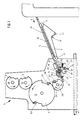
- the printing unit shown in Fig. 1, generally designated 1 comprises a plate cylinder 2, a blanket cylinder 3 and a printing cylinder 4.
- the printing cylinder 4 has double Diameter of the cylinders 2, 3 and carries two gripper systems 51, 52. It is therefore an offset printing unit.
- invention is not for application to Offset printing units limited, it can rather with everyone another type of printing unit, i.e. high-pressure or gravure printing units Find application.
- the printing press further comprises a feed table 5, which the Sheet individually in a known, not shown Be fed in the direction of arrow a.
- a feed table 5 which the Sheet individually in a known, not shown Be fed in the direction of arrow a.
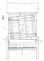
- several conveyor belts 6, 7, 8, 9 are provided, each over two deflection rollers 10, 11 and tension rollers 12, 13 run, At least one of the deflection rollers 10, 11 is driven, specifically such that the upper run of the conveyor belts in the direction of Arrow b is running.
- the conveyor belts 6 to 9 thus run underneath an acute angle to the feeding and conveying direction of the sheets, which is indicated by the arrow a.
- Deflection rollers 10, 11 with the tensioning rollers 12, 13 on a carrier 14 attached which is rotatably mounted about an axis 15 to the acute angle between the conveying direction of the bow, arrow a, and the transport direction of the conveyor belts 6 to 9, arrow b, to be able to adjust.
- a side mark 16, 17 fixed on both sides.
- the conveyor belts 6 to 9 each Bow with a transverse to the conveying direction a Movement component against the side mark 16 and cause this results in a side orientation of the sheet during its Transport. Due to the rotatable arrangement of the carrier 14 furthermore the possibility to turn the sheet against the side mark 17 to guide and align there laterally.
- One across Movement component directed in the conveying direction can also be the bow be granted in addition to in the conveying direction revolving conveyor belts or conveyor rollers blowing obliquely to it Air nozzles or an additional one running diagonally or transversely to it Conveyor belt is provided.
- a feed roller 18 arranged over the feed table extends over the entire width of the feed table 5.
- the feed roller 18 is wound a coil spring, one end of which is connected to a fixed part of the feed table 5, while the other end is attached to the conveyor roller 18.
- the Coil spring tends to move the feed roller 18 in the opposite direction arrow c to rotate.
- At both ends of the conveyor roller 18 is each a disc 21 is attached to which one end of a rope 22nd is connected and on which part of the rope is wound can be.
- the other end of the rope 22 is on a lever 23 attached, which is pivotable about an axis 24.
- Each lever 23 carries a roller 25, which by means of a fixed board 26th supported, with the other end engaging the lever 23 Compression spring 27 is held in contact with a control disk 28.
- the two control disks 28 are seated on a synchronous with the Machine speed driven shaft 29. Instead of this drive another can alternately accelerate the conveyor roller and decelerating drive are used.
- a pressure roller 32 is freely rotatable.
- the axis 30 is in turn controlled synchronously with the machine speed, that the pressure rollers 32 temporarily against the conveyor roller 18 pressed and temporarily lifted from this.
- Behind the Conveyor roller 18 is pivotable on the feed table in a known manner a pre-alignment token 33 stored, made up of several arranged across the width of the feed table Attacks exists.
- the diameter of the transfer drum 34 is smaller than the diameter of the plate cylinder 2 because the Transfer drum because of the delay on the Feed speed of the sheets a smaller medium Peripheral speed as the plate cylinder 2 or with has the same circumferential speed rotating printing cylinder 4, but after every half revolution of the impression cylinder 4 or one revolution of the plate cylinder 2 and one revolution the transfer drum 34 whose gripper system 49 one of the Gripper systems 50, 51 must face each other for sheet transfer.
- the Transfer drum can also be used with two gripper systems be carried out. Then their diameter increases corresponding.
- the transfer drum 34 is firmly seated on a shaft 35 on the a pinion 36 is also fitted.
- the pinion 36 meshes with a gear 37, which together with a support plate 38 on a to the shaft 35 parallel shaft 39 is placed.
- the support disk 38 carries four carrier rollers 40 to 43.
- the carrier rollers work in pairs with the two side flanks of a raised one spatial control curve 46 together.
- the control cam 46 is on a main drive shaft 47 of the Printing machine put on.
- the main drive shaft 47 carries a bevel gear 48 per printing unit, with which downstream gears the cylinders 2 to 4 in itself known, not shown are driven.
- the ropes 22 therefore begin unwind from the disks 21 and the conveyor roller 18 in Accelerate in the direction of arrow c. At the same time it swings Control shaft 30, the lever 31 and thereby brings the pressure roller 32nd on the arch.
- the control disks 28 are now so eccentric mounted that the levers with a further rotation of the shaft 29 23 to deflect growing paths and thus the conveyor roller 18 and as a result also accelerate the bow.
- the Clamping the sheet between the conveyor roller 18 and the Pinch rollers 32 ensure that regardless of its strength and Ripple, its at the pre-alignment mark 33 aligned front edge without the risk of misalignment Transfer drum 34 is moved.
- the arch reaches the end of the feed table 5 with one Speed slightly higher than the peripheral speed the transfer drum 34 is in this moment, so runs Sheet in the open gripper system 49 and comes to System on the front mark 50. Then the grippers close of the gripper system 49. The sheet thus runs to the front mark 50 at a speed below the speed of the Sheet when printing. A rebound or a deformation of the Arch can therefore be used despite a very large one Avoid machine speed. Furthermore, his Acceptance from the feed table 5 not to fear that he sweeps the following bow.
- the transfer drum 34 is by means of the unevenly translating gear 38 to 46 accelerates until the peripheral speed of the transfer drum 34 is approximately equal to that Circumferential speed of the printing cylinder 4 is.
- the grabs pass of the gripper system 49 of the transfer drum 34 the sheet to the Gripper e.g. of the gripper system 52 of the printing cylinder 4, which with constant high speed.
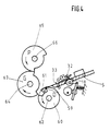
- the same feed table 5 with the conveyor roller 18, the pressure rollers 32 and the pre-alignment marker 33 are used is also provided in the first embodiment.
- a pressure cylinder 60 right away behind the end of the feed table 5 is a pressure cylinder 60 a front mark 59 and a bow on this mark defining gripper system 61 is provided.
- the one on a shaft 62 seated impression cylinder 60 acts with a blanket cylinder 63 together, which sits on a shaft 64.
- the blanket cylinder 63 is in turn connected to a plate cylinder 65 on a shaft 66 employed.
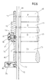
- the gear 75 is still both engaged with a gear 76 that is fixed sits on the shaft 66 of the plate cylinder 65, and a gear 77, which is firmly placed on the shaft 62 and in one area 78 has no teeth.
- On the shaft 62 is still one Carried disc 79, which carries a driving roller 80.
- the driving roller 80 can have a spatial control curve 81 cooperate with a bevel gear 83 via a shaft 82 connected is.
- the bevel gear 83 meshes with one on the Main drive shaft 67 further bevel gear 84.
- Die Control curve 81 of the non-uniformly gearbox 79 to 81 is designed so that it engages the driver roller 80 takes along when the area 78 of the gear 77 on the gear 75 passes by.
- the shape of the control curve 81 is also selected so that that in this area the support disk 79 is initially delayed and then accelerated again until the support disk 79 and thus the gear 77 again the same peripheral speed as that Have gear 75. The delay takes place down to a value in the case of the pressure cylinder 60 placed on the shaft 62 Has peripheral speed that is slightly below the Feed speed of the sheet from the feed table 5 is.
- the tooth-free area begins 78 of the gear 77 opposite the gear 75 again, so that Gear 75 the shaft 62 and thus the pressure cylinder 60 no further drives.
- the driving roller 80 arrives again in the area of the control curve 81, in which it is free of play is guided so that the drive of the printing cylinder on the Control curve 81 takes place.
- Their effective area is now delayed the printing cylinder 60 in turn to a peripheral speed in the next sheet can be taken over.
- the plate cylinder 65 and the blanket cylinder 63 are also during the Acceleration and deceleration of the printing cylinder over the Gears 71, 74, 75 and 76 at machine speed driven.
- the average Circumferential speed of the impression cylinder 60 is lower than the peripheral speed of the blanket cylinder 63 or Plate cylinder 65, which are both the same size, is the Dimension the diameter of the impression cylinder accordingly smaller.
Landscapes
- Supply, Installation And Extraction Of Printed Sheets Or Plates (AREA)
- Registering Or Overturning Sheets (AREA)
- Inking, Control Or Cleaning Of Printing Machines (AREA)
- Sheets, Magazines, And Separation Thereof (AREA)
Description
Die Erfindung betrifft eine Vorrichtung zur Übergabe von Bogen an ein mindestens einen Plattenzylinder und einen Druckzylinder aufweisendes Druckwerk einer Bogen-Rotationsdruckmaschine.The invention relates to a device for transferring sheets to at least one plate cylinder and one impression cylinder Printing unit of a sheet-fed rotary printing press.
Eine Vorrichtung zur Übergabe von Bogen an den Druckzylinder einer Bogen-Rotationsdruckmaschine zeigt die FR-A-2 287 997. Danach wird der Druckbogen von einem Anlegetisch in die Greifer einer zunächst stillstehenden Vorgreifertrommel gefördert. Sodann wird die Vorgreifertrommel mit dem Bogen auf Druckgeschwindigkeit beschleunigt und übergibt ihn mit Druckgeschwindigkeit an eine ebenfalls mit Druckgeschwindigkeit umlaufende Anlegetrommel. Von ihr wird der Bogen an den ebenfalls diese Umfangsgeschwindigkeit aufweisenden Druckzylinder übergeben. Diese Übergabevorrichtung ist hinsichtlich der Geschwindigkeit der Bogen begrenzt und setzt somit die Grenze für die Druckleistung der Bogen-Rotationsdruckmaschine. Die hohen Geschwindigkeiten, auf die die Bogen gebracht werden müssen, bedingen starke Beschleunigungen, die unzulässige Passerfehler bei der Bogenübergabe verursachen.A device for transferring sheets to the impression cylinder Sheet-fed rotary printing machine shows the FR-A-2 287 997. After that the printed sheet from a feed table into the gripper one initially stationary pre-gripper drum promoted. Then the Pre-gripper drum with the sheet at printing speed accelerates and transfers it to a printer at print speed feed drum rotating also at printing speed. Of you will bow at the same this peripheral speed hand over printing cylinder. This transfer device is limited in terms of the speed of the bow and thus sets the limit for the printing performance of the sheet-fed rotary printing press. The high speeds to which the sheets are brought must cause strong accelerations, the impermissible Cause register errors in the sheet transfer.
Die US-A-2 687 886 zeigt eine Bogen-Rotationsdruckmaschine, bei der der Bogen zunächst mittels schräg laufender Bänder seitlich ausgerichtet und anschließend zur Anlage an eine Förderwalze gebracht wird. Letztere arbeitet mit einer unter Schwerkraft ständig aufliegenden Belastungsrolle zusammen und beschleunigt den Bogen unter Reibschluß auf Druckgeschwindigkeit und schießt ihn in die Greifer eines Druckzylinders oder einer Walze, die mit ebenfalls dieser Geschwindigkeit umlaufen, ein. Auch hier ist eine zuverlässige Bogenübergabe bei höherer Geschwindigkeit nicht mehr gegeben. US-A-2 687 886 shows a sheet-fed rotary printing press in which the arch is initially to the side using oblique bands aligned and then to the system on a conveyor roller brought. The latter works constantly with a gravity resting load roller together and accelerates the bow frictional to print speed and shoots him in the Gripper of a printing cylinder or a roller that also with circulate at this speed. Here is one too reliable sheet transfer at higher speeds no longer given.
Aus der DE-A-3 305 219 und der DE-B-1 123 678 ist eine stufenweise Beschleunigung von Bogen von einem Anlegetisch zu einer Zuführtrommel oder einem Druckzylinder bekannt.From DE-A-3 305 219 and DE-B-1 123 678 is a gradual acceleration of arcs from a feed table to a feed drum or known a printing cylinder.
Außerdem ist die Verwendung von Förderwalzen zu diesem Zweck bekannt.In addition, the use of conveyor rollers to this Purpose known.
Aus der DE-A-2 452 051 ist die einstellbare Anordnung den Schrägstellung von Transportbändern zu Transportrichtung auf einem Anlegetisch bekannt. The adjustable arrangement is known from DE-A-2 452 051 the inclination of conveyor belts to the direction of transport known on a jetty.
Der Erfindung liegt die Aufgabe zugrunde, eine Vorrichtung dieser Gattung zu schaffen, die bei einfachem Aufbau mit wenigen bewegten Bogenförderelementen, dem Druckwerk pro Zeiteinheit eine große Zahl von Bogen unabhängig von deren Stärke oder Welligkeit passerhaltig zuführen kann, also den Betrieb der Druckmaschine mit sehr hohen Geschwindigkeiten ermöglicht.The invention has for its object a device of this To create genus with a simple structure with a few moving sheet conveying elements, the printing unit per unit of time a large number of sheets regardless of their strength or ripple can pass in register, that is Operation of the printing press at very high speeds enables.
Erfindungsgemäß wird dies durch Anwendung der Maßnahmen von
Anspruch 1 oder Anspruch 2 errreicht.According to the invention, this is achieved by applying the measures of
Weitere Merkmale und Vorteile der Erfindung ergeben sich aus den Unteransprüchen und der nachfolgenden Beschreibung zweier Ausführungsbeispiele der Erfindung anhand der Zeichnung. Es zeigt:
- Fig. 1
- eine schematische Seitenansicht des ersten Druckwerkes einer Bogen-Rotationsdruckmaschine,
- Fig. 2
- eine Ansicht des Anlegetisches von oben,
- Fig. 3
- eine schematische Seitenansicht eines ungleichförmig übersetzenden Getriebes.
- Fig. 4
- eine der Fig. 1 entsprechende Darstellung der wesentlichen Teile eines zweiten Ausführungsbeispiels,
- Fig. 5
- eine schematische Seitenansicht des Getriebes der Anordnung nach Fig. 4 und
- Fig. 6
- eine Ansicht des Getriebes nach Fig. 5 von vorn, wobei die Achse der Zylinder und Trommeln in eine Ebene gelegt sind.
- Fig. 1
- 2 shows a schematic side view of the first printing unit of a sheet-fed rotary printing press,
- Fig. 2
- a view of the feed table from above,
- Fig. 3
- a schematic side view of a non-uniformly translating gear.
- Fig. 4
- 1 corresponding representation of the essential parts of a second embodiment,
- Fig. 5
- is a schematic side view of the transmission of the arrangement of FIGS. 4 and
- Fig. 6
- a view of the transmission of FIG. 5 from the front, the axis of the cylinders and drums are placed in one plane.
Das in Fig. 1 dargestellte, insgesamt mit 1 bezeichnete Druckwerk
umfaßt einen Plattenzylinder 2, einen Gummituchzylinder 3 und
einen Druckzylinder 4. Der Druckzylinder 4 weist den doppelten
Durchmesser der Zylinder 2, 3 auf und trägt zwei Greifersysteme
51, 52. Es handelt sich also um ein Offsetdruckwerk. Die
Erfindung ist jedoch nicht auf die Anwendung bei
Offsetdruckwerken beschränkt, sie kann vielmehr auch bei jeder
anderen Druckwerksart, also Hochdruck- oder Tiefdruckwerken
Anwendung finden.The printing unit shown in Fig. 1, generally designated 1
comprises a
Die Druckmaschine umfaßt weiterhin einen Anlegetisch 5, dem die
Bogen einzeln in an sich bekannter nicht näher dargestellter
Weise in Richtung des Pfeiles a zugeführt werden. Im Anlegetisch
5 sind mehrere Transportbänder 6, 7, 8, 9 vorgesehen, die über je
zwei Umlenkrollen 10, 11 sowie Spannrollen 12, 13 laufen,
Mindestens eine der Umlenkrollen 10, 11 ist angetrieben, und zwar
derart, daß das obere Trum der Transportbänder in Richtung des
Pfeiles b läuft. Die Transportbänder 6 bis 9 laufen somit unter
einem spitzen Winkel zur Zuführ- und Förderrichtung der Bogen,
die mit dem Pfeil a bezeichnet ist. Zweckmäßig sind die
Umlenkrollen 10, 11 mit den Spannrollen 12, 13 an einem Träger 14
befestigt, der um eine Achse 15 drehbar gelagert ist, um den
spitzen Winkel zwischen der Förderrichtung der Bogen, Pfeil a,
und der Transportrichtung der Transportbänder 6 bis 9, Pfeil b,
einstellen zu können. The printing press further comprises a feed table 5, which the
Sheet individually in a known, not shown
Be fed in the direction of arrow a. In the feed table
5,
An dem dem Druckwerk 1 zugewandten Ende des Anlegetisches 5 sind
beiderseits je eine Seitenmarke 16, 17 fest angebracht. Bei der
Einstellung gemäß Fig. 2 führen die Transportbänder 6 bis 9 jeden
Bogen mit einer quer zur Förderrichtung a gerichteten
Bewegungskomponente gegen die Seitenmarke 16 und bewirken
hierdurch eine Seitenausrichtung des Bogens während seines
Transportes. Durch die drehbare Anordnung des Trägers 14 besteht
weiterhin die Möglichkeit, die Bogen auch gegen die Seitenmarke
17 zu führen und dort seitlich auszurichten. Eine quer zur
Förderrichtung gerichtete Bewegungskomponente kann dem Bogen auch
dadurch erteilt werden, daß zusätzlich zu in Förderrichtung
umlaufenden Förderbändern oder Förderrollen schräg dazu blasende
Luftdüsen oder ein schräg bzw. quer dazu umlaufendes zusätzliches
Förderband vorgesehen ist.At the end of the feed table 5 facing the printing unit 1
a
In Förderrichtung a hinter den Seitenmarken 16, 17 ist im
Anlegetisch eine Förderwalze 18 angeordnet, die sich über die
gesamte Breite des Anlegetisches 5 erstreckt.
Um die Achse 19
der Förderwalze 18 ist eine Spiralfeder gewickelt, deren eines Ende
an einem festen Teil des Anlegetisches 5 angeschlossen ist, während
das andere Ende an der Förderwalze 18 befestigt ist. Die
Spiralfeder hat die Tendenz, die Förderwalze 18 entgegen Richtung
des Pfeiles c zu drehen. An beiden Enden der Förderwalze 18 ist je
eine Scheibe 21 befestigt, an der das eines Ende eines Seiles 22
angeschlossen ist und auf die ein Teil des Seiles aufgewickelt
werden kann. Das andere Ende des Seiles 22 ist an je einem Hebel 23
befestigt, der um eine Achse 24 schwenkbar ist. Jeder Hebel 23
trägt eine Rolle 25, die mittels einer an einer festen Platine 26
abgestützten, mit dem anderen Ende am Hebel 23 angreifenden
Druckfeder 27 in Anlage an einer Steuerscheibe 28 gehalten ist. Die
beiden Steuerscheiben 28 sitzen fest auf einer synchron mit der
Maschinendrehzahl angetriebenen Welle 29. Anstelle dieses Antriebs
kann auch ein anderer die Förderwalze abwechselnd beschleunigender
und verzögernder Antrieb Verwendung finden. In the conveying direction a behind the
Oberhalb des Anlegetisches 5 sind an einer durchlaufenden Achse
30 mehrere Schwenkhebel 31 befestigt, an derem freien Ende je
frei drehbar eine Andruckrolle 32 gelagert ist. Die Achse 30
ist wiederum synchron zur Maschinengeschwindigkeit so gesteuert,
daß die Andruckrollen 32 zeitweilig gegen die Förderwalze
18 angedrückt und zeitweise von dieser abgehoben sind. Hinter der
Förderwalze 18 is am Anlegetisch in bekannter Weise schwenkbar
eine Vorausrichtungs-Vordermarke 33 gelagert, die aus mehreren
sich über die Breite des Anlegetisches verteilt angeordneten
Anschlägen besteht.Above the feed table 5 are on a
Oberhalb des Endes des Anlegetisches 5 ist eine Überführtrommel
34 mit einem Greifersystem 49 und einer Vordermarke 50
angeordnet. Der Durchmesser der Überführtrommel 34 ist kleiner
als der Durchmesser des Plattenzylinders 2, da die
Überführtrommel wegen der Verzögerung auf die
Zuführgeschwindigkeit der Bogen eine kleinere mittlere
Umfangsgeschwindigkeit als der Plattenzylinder 2 bzw. der mit
gleicher Umfangsgeschwindigkeit umlaufende Druckzylinder 4 hat,
aber nach jeweils einer halben Umdrehung des Druckzylinders 4
bzw. einer Umdrehung des Plattenzylinders 2 und einer Umdrehung
der Überführtrommel 34 deren Greifersystem 49 einem der
Greifersysteme 50, 51 zur Bogenübergabe gegenüberstehen muß. Die
Überführtrommel kann jedoch auch mit zwei Greifersystemen
ausgeführt werden. Dann vergrößert sich ihr Durchmesser
entsprechend.Above the end of the feed table 5 is a
Die Überführtrommel 34 sitzt fest auf einer Welle 35, auf die
weiterhin ein Ritzel 36 aufgesetzt ist. Das Ritzel 36 kämmt mit
einem Zahnrad 37, das gemeinsam mit einer Tragscheibe 38 auf eine
zur Welle 35 parallelen Welle 39 aufgesetzt ist. Die Tragscheibe
38 trägt vier Mitnehmerrollen 40 bis 43. Die Mitnehmerrollen
wirken paarweise mit den beiden Seitenflanken einer erhabenen
räumlichen Steuerkurve 46 zusammen. Die Teile 38 bis 46 bilden
ein ungleichförmig übersetzendes Getriebe, das die Überführtrommel
34 laufend von einer niedrigen auf eine hohe
Umfangsgeschwindigkeit beschleunigt, kurzfristig auf dieser hohen
Umfangsgeschwindigkeit bleibt, dann verzögert und anschließend
kurzfristig auf der niedrigen Umfangsgeschwindigkeit bleibt.The
Die Steuerkurve 46 ist auf eine Hauptantriebswelle 47 der
Druckmaschine aufgesetzt. Die Hauptantriebswelle 47 trägt
weiterhin pro Druckwerk ein Kegelrad 48, mit dem über
nachgeschaltete Zahnräder die Zylinder 2 bis 4 in an sich
bekannter, nicht dargestellter Weise angetrieben werden.The
Wird ein Bogen in Richtung des Pfeiles a auf den Anlegetisch 5
geführt, so wird er nach einer kurzen Wegstrecke von den
Transportbändern 6 bis 9 erfaßt und nunmehr in Richtung des Pfeiles
b gegen die Seitenmarke 16 geführt. Dadurch erfolgt die
Seitenausrichtung bereits während der Zufuhr jedes Bogens. Es wird
also hierfür keine zusätzliche Zeit benötigt, während der sich der
zur Seite hin auszurichtende Bogen nicht in Förderrichtung bewegt.
Infolgedessen kann die Schuppung, mit der die Bogen über den
Anlegetisch 5 laufen, sehr dicht sein. Liegt die Vorderkante des
Bogens an der Vorausrichtungs-Vordermarke 33 an, so beginnen die
Steuerscheiben 28, die Hebel 23 über die Rollen 25 entgegen der
Wirkung der Druckfedern 27 auszulenken. Die Seile 22 beginnen daher
sich von den Scheiben 21 abzuwickeln und die Förderwalze 18 in
Richtung des Pfeiles c zu beschleunigen. Gleichzeitig schwenkt die
Steuerwelle 30 den Hebel 31 und bringt dadurch die Andruckrolle 32
zur Anlage am Bogen. Die Steuerscheiben 28 sind nun so exzentrisch
gelagert, daß sie bei einer weiteren Drehung der Welle 29 die Hebel
23 um wachsende Wege auslenken und damit die Förderwalze 18 und
infolgedessen auch den Bogen beschleunigen. Dabei stellt die
Klemmung des Bogens zwischen der Förderwalze 18 und den
Andruckrollen 32 sicher, daß, unabhängig von seiner Stärke und
Welligkeit, seine an der Vorausrichtungs-Vordermarke 33
ausgerichtete Vorderkante ohne die Gefahr einer Schiefstellung zur
Überführtrommel 34 bewegt wird. If an arc is drawn in the direction of arrow a on the feed table 5
after a short distance from the
Erreicht der Bogen das Ende des Anlegetisches 5 mit einer
Geschwindigkeit, die etwas höher als die Umfangsgeschwindigkeit
der Überführtrommel 34 in diesem Augenblick ist, so läuft der
Bogen in das geöffnete Greifersystem 49 ein und kommt dabei zur
Anlage an der Vordermarke 50. Anschließend schließen die Greifer
des Greifersystems 49. Der Bogen läuft somit an die Vordermarke 50
mit einer Geschwindigkeit an, die unter der Geschwindigkeit des
Bogens beim Druck liegt. Ein Rückprallen oder eine Deformation des
Bogens läßt sich daher trotz einer sehr großen
Maschinengeschwindigkeit vermeiden. Weiterhin ist auch bei seiner
Abnahme vom Anlegetisch 5 nicht zu befürchten, daß er den
nachfolgenden Bogen mitreißt.The arch reaches the end of the feed table 5 with one
Speed slightly higher than the peripheral speed
the
Nach Übernahme des Bogens wird die Überführtrommel 34 mittels des
ungleichförmig übersetzenden Getriebes 38 bis 46 beschleunigt, bis
die Umfangsgeschwindigkeit der Überführtrommel 34 etwa gleich der
Umfangsgeschwindigkeit des Druckzylinders 4 ist. Zweckmäßig ist das
ungleichförmig übersetzende Getriebe 38 bis 46 so ausgelegt, daß
die Überführtrommel 34 noch geringfügig beschleunigt wird, wenn die
Bogenübergabe beginnt. Hierdurch wird erreicht, daß ein die exakte
Übergabe des Bogens störender Zahnflankenwechsel im Antrieb der
Überführtrommel 34 vermieden wird. Nunmehr übergeben die Greifer
des Greifersystems 49 der Überführtrommel 34 den Bogen an die
Greifer z.B. des Greifersystems 52 des Druckzylinders 4, der mit
konstanter hoher Geschwindigkeit umläuft. Dabei ergibt sich durch
den größeren Durchmesser des Druckzylinders 4 der Vorteil, daß der
Weg, der für die Bogenübergabe vom Greifersystem 49 auf das
Greifersystem 51 oder 52 zur Verfügung steht, länger als bei
Übergabe an einem Druckzylinder kleineren Durchmessers und nur
einem Greifersystem ist. Ein noch längerer Übergabeweg kann
erreicht werden, wenn auch die Überführtrommel mit zwei
Greifersystemen am Umfang und einem entsprechend größeren
Durchmesser ausgeführt wird. After taking over the sheet, the
Unmittelbar nach Übergabe des Bogens an das Greifersystem 51
verzögert das ungleichförmig übersetzende Getriebe 38 bis 46 die
Drehung der Überführtrommel 34 bis diese wiederum eine
Umfangsgeschwindigkeit erreicht, die etwas unter der
Geschwindigkeit liegt, mit der der nächste Bogen vom Anlegetisch 5
zugeführt wird.Immediately after the sheet has been transferred to the
Beim Ausführungsbeispiel nach Fig. 4 bis 6 kann wiederum der
gleiche Anlegetisch 5 mit der Förderwalze 18, den Andruckrollen
32 und der Vorausrichtungs-Vordermarke 33 Verwendung finden, der
auch beim ersten Ausführungsbeispiel vorgesehen ist. Unmittelbar
hinter dem Ende des Anlegetisches 5 ist ein Druckzylinder 60 mit
einer Vordermarke 59 und einem den Bogen an dieser Marke
festlegendem Greifersystem 61 vorgesehen. Der auf einer Welle 62
sitzende Druckzylinder 60 wirkt mit einem Gummituchzylinder 63
zusammen, der auf einer Welle 64 sitzt. Der Gummituchzylinder 63
ist seinerseits an einen Plattenzylinder 65 auf einer Welle 66
angestellt.In the embodiment of FIGS. 4 to 6, the
same feed table 5 with the
Wie sich aus den Fig. 5 und 6 ergibt, erfolgt der Antrieb der
Zylinder 60, 63 und 65 von einer Hauptantriebswelle 67. Auf diese
ist ein Kegelrad 68 aufgesetzt, das mit einem weiteren Kegelrad 69
kämmt. Fest mit dem Kegelrad 69 ist ein Ritzel 70 verbunden, das
in ein Zahnrad 71 eingreift. Das Zahnrad 71 sitzt auf einer Welle
72 auf die fest eine Transporttrommel 73 aufgesetzt ist. Die mit
Greifern versehene Transporttrommel 73 dient der Abnahme der
Bogen vom Druckzylinder 60. Das Zahnrad 71 kämmt seinerseits mit
einem Zahnrad 74, das lose drehbar auf die Welle 62 des
Druckzylinders 60 aufgesetzt ist. Das Zahnrad 74 steht mit einem
weiteren breiteren Zahnrad 75 in Eingriff, das fest auf die Welle
64 des Gummituchtuchzylinders 63 aufgesetzt ist. Das Zahnrad 75
steht weiterhin sowohl in Eingriff mit einem Zahnrad 76, das fest
auf der Welle 66 des Plattenzylinders 65 sitzt, und einem Zahnrad
77, das fest auf die Welle 62 aufgesetzt ist und in einem Bereich
78 keine Zähne aufweist. Auf die Welle 62 ist weiterhin eine
Tragscheibe 79 aufgesetzt, die eine Mitnehmerrolle 80 trägt. 5 and 6, the drive of the
Die Mitnehmerrolle 80 kann mit einer räumlichen Steuerkurve 81
zusammenwirken, die über eine Welle 82 fest mit einem Kegelrad 83
verbunden ist. Das Kegelrad 83 kämmt mit einem auf die
Hauptantriebswelle 67 aufgesetzten weiteren Kegelrad 84. Die
Steuerkurve 81 des ungleichförmig übersetzenden Getriebes 79 bis
81 ist so ausgelegt, daß sie die Mitnehmerrolle 80 formschlüssig
mitnimmt, wenn der Bereicht 78 des Zahnrades 77 am Zahnrades 75
vorbeiläuft. Die Form der Steuerkurve 81 ist weiterhin so gewählt,
daß in diesem Bereich die Tragscheibe 79 zunächst verzögert und
dann wiederum beschleunigt wird bis die Tragscheibe 79 und damit
das Zahnrad 77 wieder die gleiche Umfangsgeschwindigkeit wie das
Zahnrad 75 haben. Die Verzögerung erfolgt dabei bis auf einen Wert,
bei dem auf die Welle 62 aufgesetzte Druckzylinder 60 eine
Umfangsgeschwindigkeit hat, die geringfügig unter der
Zufuhrgeschwindigkeit des Bogens vom Anlegetisch 5 liegt.The driving
Wird dem Druckzylinder 60 vom Anlegetisch 5 mittels der Förderwalze
18 ein Bogen zugeführt, so schließen im Augenblick des Anlaufs des
Bogens an der Vordermarke 59 die Greifer des Greifersystems 61.
Unmittelbar danach beginnt die Steuerkkurve 81 die Welle 62 des
Druckzylinders 60 zu beschleunigen. Hat der Druckzylinder 60 die
Umfangsgeschwindigkei des Gummituchzylinders 63 erreicht, so greift
die Verzahnung des Zahnrades 77 in das Zahnrad 75 ein. Nunmehr wird
der Druckzylinder 60 über das Zahnrad 75 angetrieben. In diesem
Bereich ist die Rolle 80 mit der Steuerkurve 81 nicht im Eingriff
so daß sie den Antrieb vom Zahnrad 75 nicht beeinträchtigt. Nunmehr
erfolgt der Druck des am Druckzylinder 60 geführten Bogens. Dieser
Bogen wird dann in bekannter, nicht näher dargestellter Weise über
die Transporttrommel 73 abgeführt.Is the
Nach Beendigung des Drucks steht der Beginn des zahnfreien Bereichs
78 des Zahnrades 77 dem Zahnrad 75 erneut gegenüber, so daß das
Zahnrad 75 die Welle 62 und damit den Druckzylinder 60 nicht weiter
antreibt. In diesem Augenblick gelangt die Mitnehmerrolle 80
wiederum in den Bereich der Steuerkurve 81, in dem sie spielfrei
geführt ist, so daß der Antrieb des Druckzylinders über die
Steuerkurve 81 erfolgt. Deren wirksamer Bereich verzögert nunmehr
den Druckzylinder 60 wiederum auf eine Umfangsgeschwindigkeit in
der der nächste Bogen übernommen werden kann. Der Plattenzylinder
65 und der Gummituchzylinder 63 sind auch während der
Beschleunigung und Verzögerung des Druckzylinders über die
Zahnräder 71, 74, 75 und 76 mit Maschinengeschwindigkeit
angetrieben.After printing is complete, the tooth-free area begins
78 of the
Da, bezogen auf eine Umdrehung die durchschnittliche
Umfangsgeschwindigkeit des Druckzylinders 60 niedriger ist als
die Umfangsgeschwindigkeit des Gummituchzylinders 63 oder des
Plattenzylinders 65, die beide gleich groß sind, ist der
Durchmesser des Druckzylinders entsprechend kleiner bemessen.There, based on one revolution, the average
Circumferential speed of the
Wie die vorstehenden Ausführungen zeigen, ist die Erfindung nicht auf die dargestellten Ausführungsbeispiele beschränkt. Beispielsweise könnten auch andere ungleichförmig übersetzende Getriebe ihre Anwendung finden.As the above remarks show, the invention is not limited to the illustrated embodiments. For example, other non-uniform translators could also be used Gearboxes find their application.
Claims (8)
- Device for transferring sheets to a printing unit, having at least one plate cylinder (2) and one impression cylinder (4), of a sheet-fed rotary printing machine, having a feed table (5) and a transfer drum (34) arranged at the end of the feed table (5), having at least one front marker (50) and a gripper system (49) holding the sheets on the front marker (50), the gripper system co-operating with the impression cylinder (4) carrying grippers, transport belts (6 to 9) being provided in the feed table (5) which move each sheet with an additional movement component directed transversely to the direction of feed to the printing unit, and circulating with an incline to the direction of feed, the sheet being capable of guidance by these transport means against a fixed lateral marker (16, 17) and a pre-alignment front marker (33), and in the end of the feed table (5) facing the printing unit (1) there is provided a continuous conveyor roller (18), which extends over the entire width of the feed table (5) and co-operates with pressure rollers (32) starting and stopping in sequence, the conveyor roller (18) being driven by means of an alternately accelerating and decelerating drive (21 to 29) and entraining the sheet during its acceleration phase in friction contact and thus accelerating it in the feed direction, furthermore the transfer drum (34) is arranged above the end of the feed table (5) and is driven by means of a non-uniformly transmitting gear unit (38 to 46) in such a way that when a sheet is transferred it is circulating at a speed below the speed of the sheet, then it accelerates, and when the sheet is passed on it has approximately the same circumferential speed as the impression cylinder (4), and the acute angle of the inclined setting between the transport direction of the transport belts (6 to 9) and the direction of feed of the sheets is adjustable.
- Device for transferring sheets to a printing unit, having at least one plate cylinder (63) and one impression cylinder (60), of a sheet-fed rotary printing machine, having a feed table (5), transport belts (6 to 9) being provided in the feed table (5) which move each sheet with an additional movement component directed transversely to the direction of feed to the printing unit, and which circulate with an incline to the direction of feed of the sheets, the sheet being capable of guidance by these transport belts against a fixed lateral marker (16, 17) and a pre-alignment front marker (33), in the end of the feed table (5) facing the printing unit there is further provided a continuous conveyor roller (18) which extends over the entire width of the feed table (5) and which co-operates with pressure rollers (32) starting and stopping in sequence, the conveyor roller (18) being driven by means of an alternately accelerating and decelerating drive (21 to 29) and entraining the sheet during its acceleration phase in friction contact and thus accelerating it in the feed direction, furthermore behind the feed table (5) there is arranged the impression cylinder (60) which has at least a front marker (59) and a gripper system (61) holding the sheets on the front marker, and the impression cylinder (60) is driven using a non-uniformly transmitting gear unit (79 to 81) in such a way that when a sheet is transferred it is circulating at a circumferential speed below the speed of the sheet, then it accelerates, and during the printing it circulates at the same circumferential speed as the plate cylinder (63).
- Device according to claim 2, characterised in that the acute angle of the inclined setting between the transport direction of the transport belts (6 to 9) and the direction of feed of the sheets is adjustable.
- Device according to claim 1 or 2, characterised in that the impression cylinder (4) has two gripper systems (51, 52) on the circumference.
- Device according to claim 1, characterised in that the transfer drum has two gripper systems on the circumference.
- Device according to claim 1 or 2, characterised in that the non-uniformly transmitting gear unit (38 to 46, 79 to 81) is a three-dimensional cam gear unit.
- Device according to claim 1, characterised in that the non-uniformly transmitting gear unit (38 to 46) is designed so that sheet transfer to the impression cylinder (4) is effected at the end of the acceleration phase of the transfer drum (34).
- Device according to claim 2, characterised in that the impression cylinder (60) is driven in the acceleration phase and deceleration phase and during pick-up of the sheet from the feed table (5) by means of the non-uniformly transmitting gear unit (79 to 81), but in the printing phase by means of the drive (68 to 71, 74 to 77) of the plate cylinder (65).
Applications Claiming Priority (2)
| Application Number | Priority Date | Filing Date | Title |
|---|---|---|---|
| DE19873726780 DE3726780A1 (en) | 1987-08-12 | 1987-08-12 | DEVICE FOR TRANSFERING BOWS |
| DE3726780 | 1987-08-12 |
Publications (4)
| Publication Number | Publication Date |
|---|---|
| EP0303053A2 EP0303053A2 (en) | 1989-02-15 |
| EP0303053A3 EP0303053A3 (en) | 1990-04-04 |
| EP0303053B1 EP0303053B1 (en) | 1992-09-09 |
| EP0303053B2 true EP0303053B2 (en) | 2000-10-25 |
Family
ID=6333561
Family Applications (1)
| Application Number | Title | Priority Date | Filing Date |
|---|---|---|---|
| EP88110921A Expired - Lifetime EP0303053B2 (en) | 1987-08-12 | 1988-07-08 | Sheet-transferring device |
Country Status (5)
| Country | Link |
|---|---|
| US (1) | US4825762A (en) |
| EP (1) | EP0303053B2 (en) |
| JP (1) | JP2752381B2 (en) |
| CA (1) | CA1287255C (en) |
| DE (2) | DE3726780A1 (en) |
Families Citing this family (17)
| Publication number | Priority date | Publication date | Assignee | Title |
|---|---|---|---|---|
| GB8619504D0 (en) * | 1986-08-11 | 1986-09-24 | Rockwell Graphic Systems Ltd | Accelerating drive member |
| DE4020730C2 (en) * | 1990-06-29 | 1999-04-15 | Krause Biagosch Gmbh | Method and device for improving the stack quality of a sheet stack |
| DE4431683C2 (en) * | 1994-09-06 | 1998-11-26 | Kba Planeta Ag | Drive a sheet accelerator |
| DE4431680C2 (en) * | 1994-09-06 | 1998-11-26 | Kba Planeta Ag | Drive a sheet acceleration system |
| DE4431682C2 (en) * | 1994-09-06 | 1998-11-26 | Kba Planeta Ag | Curve-controlled arc acceleration system |
| DE4431684C2 (en) * | 1994-09-06 | 1998-12-03 | Kba Planeta Ag | Device for driving a sheet accelerator |
| DE4435264C2 (en) * | 1994-10-01 | 2001-05-10 | Heidelberger Druckmasch Ag | Bow hold down |
| US5584246A (en) * | 1995-06-09 | 1996-12-17 | Werner Kammann Maschinenfabrik Gmbh | Process and apparatus for printing on flat individual articles |
| DE19901699B4 (en) * | 1998-02-04 | 2007-11-15 | Heidelberger Druckmaschinen Ag | Method and device for carrying out the method for eliminating rhythmic registration errors in rotary printing machines |
| DE10020648A1 (en) * | 2000-04-27 | 2001-10-31 | Heidelberger Druckmasch Ag | Sheet-fed printer has sheet-separator, feeder, with marker, preliminary gripper, feeder and transporter drums, screen roller and ductor |
| JP2002087635A (en) * | 2000-09-12 | 2002-03-27 | Canon Inc | Sheet material conveying device, recording device including the same, and imaging device with recording mechanism |
| DE102004019220A1 (en) * | 2004-04-21 | 2005-11-10 | Koenig & Bauer Ag | Sheet feed system comprises suction grippers which feed sheets through rollers on to belt table, feed directions of rollers and table being at angle to direction in which grippers transport sheets |
| DK1780155T3 (en) * | 2004-10-14 | 2012-01-23 | Muller Martini Mailroom Systems Inc | Product feeder with accelerator and deceleration devices |
| DE102004057842A1 (en) * | 2004-12-01 | 2006-06-08 | Koenig & Bauer Ag | Device for treatment of sheets has feed table on which sheets are placed aligned against front marks and end rollers which are arranged at the feed table at distance from front marks and lying on feed line |
| JP5838128B2 (en) * | 2012-05-31 | 2015-12-24 | 株式会社木田鉄工所 | Transport device |
| CN103144424B (en) * | 2013-03-07 | 2016-01-20 | 天津长荣印刷设备股份有限公司 | A kind of electronic registering system and method for work thereof |
| EP3386767A4 (en) * | 2015-12-09 | 2019-07-31 | Hewlett-Packard Development Company, L.P. | Media registration with puller clamp |
Family Cites Families (25)
| Publication number | Priority date | Publication date | Assignee | Title |
|---|---|---|---|---|
| US2335954A (en) * | 1938-09-16 | 1943-12-07 | Ditto Inc | Duplicating machine |
| US2687886A (en) * | 1950-10-21 | 1954-08-31 | Alphonse W Pitner | Registering apparatus for printing machines |
| US2708405A (en) * | 1951-08-17 | 1955-05-17 | Miller Printing Machinery Co | Printing press feed and registering mechanism |
| GB1187254A (en) * | 1967-09-26 | 1970-04-08 | Gestetner Ltd | Offset Printing Apparatus |
| US3858508A (en) * | 1969-09-15 | 1975-01-07 | Ricoh Kk | Offset printing machine |
| DE2062503A1 (en) * | 1970-12-18 | 1972-06-22 | Koenig & Bauer Schnellpressfab | Sheet feeding on printing machines |
| IT991860B (en) * | 1973-07-25 | 1975-08-30 | Nebiolo Spa | ROTARY PRINTING MACHINE FOR SINGLE SHEETS |
| SE375511B (en) * | 1973-08-13 | 1975-04-21 | Svecia Silkscreen Maskiner Ab | |
| DE2449629A1 (en) * | 1974-10-18 | 1976-04-29 | Maschf Augsburg Nuernberg Ag | SHEET FEEDING DEVICE FOR ROTARY PRINTING MACHINES |
| DE2452051A1 (en) * | 1974-11-02 | 1976-05-06 | Maschf Augsburg Nuernberg Ag | Equipment for lining up sheets in rotating printing machine - has number of transport belts with guide rollers pivotably mounted in transport plane |
| US3954494A (en) * | 1974-12-30 | 1976-05-04 | Chevron Research Company | Wax-flux composition containing a succinimide salt of an alkylaryl sulfonic acid for soldering |
| DD126254A1 (en) * | 1976-06-18 | 1977-07-06 | ||
| DE7713720U1 (en) * | 1977-04-30 | 1979-04-05 | Raes, Karl, 6201 Wildsachsen | PRINTING UNIT OF A SHEET PRINTING MACHINE |
| DE2720675C2 (en) * | 1977-05-07 | 1982-09-02 | M.A.N. Maschinenfabrik Augsburg-Nürnberg AG, 8900 Augsburg | Sheet feeding device for a rotary printing press |
| DE2744925C2 (en) * | 1977-10-06 | 1986-06-12 | Koenig & Bauer AG, 8700 Würzburg | Device on a stop drum for a sheet-fed rotary printing press |
| DD142694A1 (en) * | 1979-04-02 | 1980-07-09 | Guenter Weisbach | ARC PRINTING MACHINE WITH A BOTTOM PRE-GRIPPER |
| JPS57136744U (en) * | 1981-02-20 | 1982-08-26 | ||
| DE3108808C2 (en) * | 1981-03-07 | 1985-02-21 | M.A.N.- Roland Druckmaschinen AG, 6050 Offenbach | Sheet-fed rotary planographic printing machine |
| JPS57197164A (en) * | 1981-05-30 | 1982-12-03 | Komori Printing Mach Co Ltd | Monochromatic sheet-fed off-set press |
| JPS5862643U (en) * | 1981-10-22 | 1983-04-27 | 三菱重工業株式会社 | Paper feed cylinder drive device of printing press |
| DE3318117A1 (en) * | 1982-05-20 | 1983-11-24 | International Standard Electric Corp., 10022 New York, N.Y. | Sheet-aligning device |
| JPS58181536U (en) * | 1982-05-31 | 1983-12-03 | リョービ株式会社 | Double-sided printing machine paper feed device |
| GB2166419B (en) * | 1984-09-28 | 1988-05-05 | Rotaprint Plc | Sheet registration device and method |
| DE3511897A1 (en) * | 1985-04-01 | 1986-10-09 | Mabeg Maschinenbau Gmbh Nachf. Hense & Pleines Gmbh & Co, 6050 Offenbach | DEVICE FOR SIDE ALIGNMENT OF ARCH |
| DE8514775U1 (en) * | 1985-05-20 | 1985-06-27 | Heidelberger Druckmaschinen Ag, 6900 Heidelberg | Drive for a sheet transport mechanism on the feeder of a rotary printing press |
-
1987
- 1987-08-12 DE DE19873726780 patent/DE3726780A1/en not_active Withdrawn
-
1988
- 1988-07-08 DE DE8888110921T patent/DE3874459D1/en not_active Expired - Lifetime
- 1988-07-08 EP EP88110921A patent/EP0303053B2/en not_active Expired - Lifetime
- 1988-08-02 US US07/227,368 patent/US4825762A/en not_active Expired - Fee Related
- 1988-08-09 JP JP63197307A patent/JP2752381B2/en not_active Expired - Fee Related
- 1988-08-09 CA CA000574216A patent/CA1287255C/en not_active Expired - Lifetime
Also Published As
| Publication number | Publication date |
|---|---|
| EP0303053B1 (en) | 1992-09-09 |
| DE3726780A1 (en) | 1989-02-23 |
| EP0303053A2 (en) | 1989-02-15 |
| US4825762A (en) | 1989-05-02 |
| JP2752381B2 (en) | 1998-05-18 |
| EP0303053A3 (en) | 1990-04-04 |
| CA1287255C (en) | 1991-08-06 |
| DE3874459D1 (en) | 1992-10-15 |
| JPS6469344A (en) | 1989-03-15 |
Similar Documents
| Publication | Publication Date | Title |
|---|---|---|
| EP0303053B2 (en) | Sheet-transferring device | |
| DE2435665A1 (en) | ROTARY PRINTING MACHINE | |
| EP0059873B1 (en) | Device for stripping printed products of the delivery fans of a folding apparatus | |
| DE10047395B4 (en) | Transport system for flat products | |
| EP0498068A1 (en) | Folder, in which the folded articles are transported using transportation means ,idlers and conveyors | |
| EP1479627B1 (en) | Device for aligning sheets | |
| DE19620938A1 (en) | Positioning of printed sheets on stack | |
| EP0429884A1 (en) | Folder for a printing press | |
| DE69024857T2 (en) | Sheet feeder | |
| DE2750792B2 (en) | Folder | |
| EP1209111A2 (en) | Device for depositing sheets | |
| DE3230846C2 (en) | Device for conveying sheets or bundles of sheets | |
| DE19957574C2 (en) | Device for placing sheets on a stack | |
| EP0405107A1 (en) | Device for separating of stacked sheets of paper | |
| DE1923625C3 (en) | Device for feeding sheets for a sheet-fed rotary printing press | |
| DE2810874C2 (en) | Device for controlling the opening time of the grippers of a floor boom | |
| DE3305219C2 (en) | ||
| DE3107807C2 (en) | Sheet accelerator | |
| DE3629080C2 (en) | ||
| DE2624170C3 (en) | Side alignment device | |
| DE3401819A1 (en) | FEEDING DEVICE FOR A SHEET PROCESSING MACHINE PROVIDED WITH A CONTINUOUSLY FEEDING DEVICE | |
| DE3332809C2 (en) | Belt delay section for a folder | |
| EP0365847A2 (en) | Retarding device for the delivery end of a sheet-printing machine | |
| DE1913844C3 (en) | Drive device of a rotating pre-gripper drum with pre-grippers for laying sheets on a cylinder | |
| DE2457070C3 (en) | Device for the lateral alignment of sheets |
Legal Events
| Date | Code | Title | Description |
|---|---|---|---|
| PUAI | Public reference made under article 153(3) epc to a published international application that has entered the european phase |
Free format text: ORIGINAL CODE: 0009012 |
|
| AK | Designated contracting states |
Kind code of ref document: A2 Designated state(s): CH DE FR GB IT LI NL SE |
|
| PUAL | Search report despatched |
Free format text: ORIGINAL CODE: 0009013 |
|
| AK | Designated contracting states |
Kind code of ref document: A3 Designated state(s): CH DE FR GB IT LI NL SE |
|
| 17P | Request for examination filed |
Effective date: 19900321 |
|
| 17Q | First examination report despatched |
Effective date: 19910903 |
|
| GRAA | (expected) grant |
Free format text: ORIGINAL CODE: 0009210 |
|
| AK | Designated contracting states |
Kind code of ref document: B1 Designated state(s): CH DE FR GB IT LI NL SE |
|
| ITF | It: translation for a ep patent filed | ||
| REF | Corresponds to: |
Ref document number: 3874459 Country of ref document: DE Date of ref document: 19921015 |
|
| ET | Fr: translation filed | ||
| GBT | Gb: translation of ep patent filed (gb section 77(6)(a)/1977) |
Effective date: 19921201 |
|
| PLBI | Opposition filed |
Free format text: ORIGINAL CODE: 0009260 |
|
| PLBI | Opposition filed |
Free format text: ORIGINAL CODE: 0009260 |
|
| 26 | Opposition filed |
Opponent name: KBA-PLANETA AG Effective date: 19930608 |
|
| 26 | Opposition filed |
Opponent name: KOENIG & BAUER AKTIENGESELLSCHAFT Effective date: 19930609 Opponent name: KBA-PLANETA AG Effective date: 19930608 |
|
| NLR1 | Nl: opposition has been filed with the epo |
Opponent name: KBA-PLANETA AG |
|
| EAL | Se: european patent in force in sweden |
Ref document number: 88110921.9 |
|
| PLAB | Opposition data, opponent's data or that of the opponent's representative modified |
Free format text: ORIGINAL CODE: 0009299OPPO |
|
| R26 | Opposition filed (corrected) |
Opponent name: KBA - PLANETA AG * 930609 KOENIG & BAUER AKTIENGES Effective date: 19930608 |
|
| PLAW | Interlocutory decision in opposition |
Free format text: ORIGINAL CODE: EPIDOS IDOP |
|
| APAE | Appeal reference modified |
Free format text: ORIGINAL CODE: EPIDOS REFNO |
|
| APAC | Appeal dossier modified |
Free format text: ORIGINAL CODE: EPIDOS NOAPO |
|
| APAC | Appeal dossier modified |
Free format text: ORIGINAL CODE: EPIDOS NOAPO |
|
| PLBQ | Unpublished change to opponent data |
Free format text: ORIGINAL CODE: EPIDOS OPPO |
|
| PLAB | Opposition data, opponent's data or that of the opponent's representative modified |
Free format text: ORIGINAL CODE: 0009299OPPO |
|
| R26 | Opposition filed (corrected) |
Opponent name: KOENIG & BAUER AKTIENGESELLSCHAFT * 19930609 KOENI Effective date: 19930608 |
|
| APAC | Appeal dossier modified |
Free format text: ORIGINAL CODE: EPIDOS NOAPO |
|
| NLR1 | Nl: opposition has been filed with the epo |
Opponent name: KOENIG & BAUER AKTIENGESELLSCHAFT |
|
| PLBQ | Unpublished change to opponent data |
Free format text: ORIGINAL CODE: EPIDOS OPPO |
|
| PLAW | Interlocutory decision in opposition |
Free format text: ORIGINAL CODE: EPIDOS IDOP |
|
| PLAB | Opposition data, opponent's data or that of the opponent's representative modified |
Free format text: ORIGINAL CODE: 0009299OPPO |
|
| R26 | Opposition filed (corrected) |
Opponent name: KOENIG & BAUER AKTIENGESELLSCHAFT * 19930609 KOENI Effective date: 19930608 |
|
| PUAH | Patent maintained in amended form |
Free format text: ORIGINAL CODE: 0009272 |
|
| STAA | Information on the status of an ep patent application or granted ep patent |
Free format text: STATUS: PATENT MAINTAINED AS AMENDED |
|
| NLR1 | Nl: opposition has been filed with the epo |
Opponent name: KOENIG & BAUER AKTIENGESELLSCHAFT |
|
| ITF | It: translation for a ep patent filed | ||
| 27A | Patent maintained in amended form |
Effective date: 20001025 |
|
| AK | Designated contracting states |
Kind code of ref document: B2 Designated state(s): CH DE FR GB IT LI NL SE |
|
| REG | Reference to a national code |
Ref country code: CH Ref legal event code: AEN Free format text: AUFRECHTERHALTUNG DES PATENTES IN GEAENDERTER FORM |
|
| NLR2 | Nl: decision of opposition | ||
| ET3 | Fr: translation filed ** decision concerning opposition | ||
| GBTA | Gb: translation of amended ep patent filed (gb section 77(6)(b)/1977) | ||
| NLR3 | Nl: receipt of modified translations in the netherlands language after an opposition procedure | ||
| REG | Reference to a national code |
Ref country code: GB Ref legal event code: IF02 |
|
| PGFP | Annual fee paid to national office [announced via postgrant information from national office to epo] |
Ref country code: CH Payment date: 20020619 Year of fee payment: 15 |
|
| PGFP | Annual fee paid to national office [announced via postgrant information from national office to epo] |
Ref country code: SE Payment date: 20020625 Year of fee payment: 15 Ref country code: NL Payment date: 20020625 Year of fee payment: 15 |
|
| PGFP | Annual fee paid to national office [announced via postgrant information from national office to epo] |
Ref country code: GB Payment date: 20020628 Year of fee payment: 15 |
|
| PGFP | Annual fee paid to national office [announced via postgrant information from national office to epo] |
Ref country code: FR Payment date: 20020711 Year of fee payment: 15 Ref country code: DE Payment date: 20020711 Year of fee payment: 15 |
|
| PG25 | Lapsed in a contracting state [announced via postgrant information from national office to epo] |
Ref country code: GB Free format text: LAPSE BECAUSE OF NON-PAYMENT OF DUE FEES Effective date: 20030708 |
|
| PG25 | Lapsed in a contracting state [announced via postgrant information from national office to epo] |
Ref country code: SE Free format text: LAPSE BECAUSE OF NON-PAYMENT OF DUE FEES Effective date: 20030709 |
|
| PG25 | Lapsed in a contracting state [announced via postgrant information from national office to epo] |
Ref country code: LI Free format text: LAPSE BECAUSE OF NON-PAYMENT OF DUE FEES Effective date: 20030731 Ref country code: CH Free format text: LAPSE BECAUSE OF NON-PAYMENT OF DUE FEES Effective date: 20030731 |
|
| PG25 | Lapsed in a contracting state [announced via postgrant information from national office to epo] |
Ref country code: NL Free format text: LAPSE BECAUSE OF NON-PAYMENT OF DUE FEES Effective date: 20040201 |
|
| PG25 | Lapsed in a contracting state [announced via postgrant information from national office to epo] |
Ref country code: DE Free format text: LAPSE BECAUSE OF NON-PAYMENT OF DUE FEES Effective date: 20040203 |
|
| GBPC | Gb: european patent ceased through non-payment of renewal fee |
Effective date: 20030708 |
|
| EUG | Se: european patent has lapsed | ||
| REG | Reference to a national code |
Ref country code: CH Ref legal event code: PL |
|
| PG25 | Lapsed in a contracting state [announced via postgrant information from national office to epo] |
Ref country code: FR Free format text: LAPSE BECAUSE OF NON-PAYMENT OF DUE FEES Effective date: 20040331 |
|
| NLV4 | Nl: lapsed or anulled due to non-payment of the annual fee |
Effective date: 20040201 |
|
| REG | Reference to a national code |
Ref country code: FR Ref legal event code: ST |
|
| PG25 | Lapsed in a contracting state [announced via postgrant information from national office to epo] |
Ref country code: IT Free format text: LAPSE BECAUSE OF NON-PAYMENT OF DUE FEES;WARNING: LAPSES OF ITALIAN PATENTS WITH EFFECTIVE DATE BEFORE 2007 MAY HAVE OCCURRED AT ANY TIME BEFORE 2007. THE CORRECT EFFECTIVE DATE MAY BE DIFFERENT FROM THE ONE RECORDED. Effective date: 20050708 |
|
| APAH | Appeal reference modified |
Free format text: ORIGINAL CODE: EPIDOSCREFNO |