EP0301503B1 - Heat pump system - Google Patents
Heat pump system Download PDFInfo
- Publication number
- EP0301503B1 EP0301503B1 EP88112126A EP88112126A EP0301503B1 EP 0301503 B1 EP0301503 B1 EP 0301503B1 EP 88112126 A EP88112126 A EP 88112126A EP 88112126 A EP88112126 A EP 88112126A EP 0301503 B1 EP0301503 B1 EP 0301503B1
- Authority
- EP
- European Patent Office
- Prior art keywords
- coolant
- heat exchanger
- side heat
- fractionating
- utility
- Prior art date
- Legal status (The legal status is an assumption and is not a legal conclusion. Google has not performed a legal analysis and makes no representation as to the accuracy of the status listed.)
- Expired - Lifetime
Links
- 239000002826 coolant Substances 0.000 claims description 217
- 239000012530 fluid Substances 0.000 claims description 49
- 238000010438 heat treatment Methods 0.000 claims description 28
- 238000001816 cooling Methods 0.000 claims description 23
- 239000003638 chemical reducing agent Substances 0.000 claims description 22
- 238000009835 boiling Methods 0.000 description 96
- 239000007788 liquid Substances 0.000 description 30
- 230000001174 ascending effect Effects 0.000 description 20
- 230000000694 effects Effects 0.000 description 14
- 238000009833 condensation Methods 0.000 description 6
- 230000005494 condensation Effects 0.000 description 6
- 238000000034 method Methods 0.000 description 6
- 238000010586 diagram Methods 0.000 description 5
- 238000011144 upstream manufacturing Methods 0.000 description 5
- 239000000463 material Substances 0.000 description 4
- XLYOFNOQVPJJNP-UHFFFAOYSA-N water Substances O XLYOFNOQVPJJNP-UHFFFAOYSA-N 0.000 description 4
- 244000309466 calf Species 0.000 description 3
- 238000004519 manufacturing process Methods 0.000 description 2
- 238000011084 recovery Methods 0.000 description 2
- 238000009834 vaporization Methods 0.000 description 2
- 230000008016 vaporization Effects 0.000 description 2
- 238000006243 chemical reaction Methods 0.000 description 1
- 238000010276 construction Methods 0.000 description 1
- 230000000717 retained effect Effects 0.000 description 1
- 238000000926 separation method Methods 0.000 description 1
Images


Classifications
-
- F—MECHANICAL ENGINEERING; LIGHTING; HEATING; WEAPONS; BLASTING
- F25—REFRIGERATION OR COOLING; COMBINED HEATING AND REFRIGERATION SYSTEMS; HEAT PUMP SYSTEMS; MANUFACTURE OR STORAGE OF ICE; LIQUEFACTION SOLIDIFICATION OF GASES
- F25B—REFRIGERATION MACHINES, PLANTS OR SYSTEMS; COMBINED HEATING AND REFRIGERATION SYSTEMS; HEAT PUMP SYSTEMS
- F25B9/00—Compression machines, plants or systems, in which the refrigerant is air or other gas of low boiling point
- F25B9/002—Compression machines, plants or systems, in which the refrigerant is air or other gas of low boiling point characterised by the refrigerant
- F25B9/006—Compression machines, plants or systems, in which the refrigerant is air or other gas of low boiling point characterised by the refrigerant the refrigerant containing more than one component
-
- F—MECHANICAL ENGINEERING; LIGHTING; HEATING; WEAPONS; BLASTING
- F25—REFRIGERATION OR COOLING; COMBINED HEATING AND REFRIGERATION SYSTEMS; HEAT PUMP SYSTEMS; MANUFACTURE OR STORAGE OF ICE; LIQUEFACTION SOLIDIFICATION OF GASES
- F25B—REFRIGERATION MACHINES, PLANTS OR SYSTEMS; COMBINED HEATING AND REFRIGERATION SYSTEMS; HEAT PUMP SYSTEMS
- F25B13/00—Compression machines, plants or systems, with reversible cycle
-
- F—MECHANICAL ENGINEERING; LIGHTING; HEATING; WEAPONS; BLASTING
- F25—REFRIGERATION OR COOLING; COMBINED HEATING AND REFRIGERATION SYSTEMS; HEAT PUMP SYSTEMS; MANUFACTURE OR STORAGE OF ICE; LIQUEFACTION SOLIDIFICATION OF GASES
- F25B—REFRIGERATION MACHINES, PLANTS OR SYSTEMS; COMBINED HEATING AND REFRIGERATION SYSTEMS; HEAT PUMP SYSTEMS
- F25B2341/00—Details of ejectors not being used as compression device; Details of flow restrictors or expansion valves
- F25B2341/001—Ejectors not being used as compression device
- F25B2341/0014—Ejectors with a high pressure hot primary flow from a compressor discharge
Definitions
- the present invention relates to a heat pump system operable with the use of a non-azeotropic mixed coolant and capable of changing the composition of the non-azeotropic mixed coolant while storing a high boiling point coolant separated from the non-azeotropic mixed coolant.
- a multiple fluid refrigerating system which comprises a compressor, a condenser, an expansion valve as throttling device and an evaporator. Furthermore, a rectifier is provided and has an upper end fluid-connected with the exit side of the condenser. A reservoir portion is disposed beneath the rectifier and has a bottom fluid-connected through a valve to the inlet side of the evaporator. Moreover, a heater is provided for heating the coolant in the reservoir.
- the prior art heat pump system of the construction described above is selectively operable in one of the two modes; the non-fractionating mode in which the system operates with the mixed coolant filled therein without altering the composition thereof, and the fractionating mode in which, while a high boiling point coolant is stored, the system operates with the composition rich of a low boiling point coolant.
- the method practiced by the prior art system for changing the composition of the non-azeotropic mixed coolant filled therein will be described.
- the reservoir merely stores an excessive coolant and, during the closure of the valve, it stores the coolant, but during the opening of the valve, the coolant is in part stored and in part passed to the evaporator through the pressure reducer. Accordingly, the main fluid circuit operates with the mixed coolant whose composition is rich of a high boiling point coolant filled in the system.
- a low boiling point coolant contained in the coolant stored in the reservoir is evaporated to pass upwardly through the interior of the fractionating separator.
- a liquid coolant is supplied from the exhibit of the condenser by way of a piping to the rectifier in which fractionating takes place by the effect of a gas-liquid contact so that the gaseous medium which ascends becomes rich of the low boiling point coolant while the gaseous medium which descends becomes rich of the high boiling point cooling, allowing the high boiling point coolant to be stored in the reservoir in the form of a condensed liquid.
- the ascending gaseous medium rich of the low boiling point coolant flows into the main fluid circuit which now operates with the composition rich of the low boiling point coolant.
- the heat pump system of such a composition-variable type is applied in, for example, a hot-water supply system and is ususally operated with the filled composition rich of the high boiling point coolant so that, during the use thereof, a hot water can be available.
- the heat pump system can be operated with the composition rich of the low boiling point coolant having a high heating capability.
- the prior art heat pump system of the above described type has a problem in that, since the fractionating is carried out by the use of the heater, the energy conversion efficiency tends to be lowered at the time the composition is changed. In other words, the amount of heat produced by the heater is merely utilized for the production of the gaseous medium for the fractionating and, for example, no utilization by the heat recovery to the site of use where hot water is actually utilized is effected.
- the present invention has for its essential object to provide a refrigerating cycle system wherein the amount of heat utilized for the production of the gaseous medium can be effectively utilized and wherein the fractionating can be promoted.
- the present invention provides a heat pump system which comprises: a main heat pump circuit filled with non-azeotropic mixed coolant and including a compressor, a utility-side heat exchanger, a throttling device, a source heat exchanger, a fractionating separator having an upper end fluid-connected with an exit side of the utility-side heat exchanger, and a reservoir disposed beneath the fractionating separator and having a bottom fluid-connected through a shut-off valve to the inlet side of the fource-side heat exchanger characterized by a low pressure piping connected between the shut-off valve and the inlet side of the fource-side heat exchanger, and a coolant ejector disposed between the compressor and the utility-side heat exchanger, wherein a gaseous medium generated from the fractionating separator when the reservoir is heated is guided to a suction port of the coolant ejector to flow into the main heat pump circuit.
- the coolant ejector is provided upstream of a utility-side heat exchanger (condenser) with respect to the direction of flow of the coolant and has a suction port fluid-connected with the upper end of the fractionating separator so that, during the fractionating mode, the low boiling point coolant contained in the coolant stored in the reservoir can be mainly evaporated by the heater and the resultant gaseous medium rich of the low boiling point coolant ascending through the interior of the fractionating separator is guided to a suction port of a coolant ejector disposed upstream of the condenser, wherefore the amount of heat produced by the heater can be effectively utilized when the gaseous medium is fed back to the condenser for condensation thereof.
- a utility-side heat exchanger condenser
- a heat pump system comprises a main fluid circuit including a compressor 11, a utility-side heat exchanger (condenser) 12, a throttling device 13 and a source-side heat exchanger (evaporator) 14, all fluid-connected in a manner as shown.
- a fractionating separator 15 has an upper end fluid-connected with an outlet of the utility-side heat exchanger 12 and also with a suction port of a coolant ejector 16 disposed upstream of the utility-side heat exchanger 12 with respect to the direction of flow of medium, that is, on one side adjacent an inlet of the utility-side heat exchanger 12.
- the fractionating separator 15 has disposed therebelow a reservoir 18 having a heater 17 built therein, the bottom of said reservoir 18 being fluid connected with the source-side heat exchanger 14 through a shut-off valve 19 and a pressure reducer 20.
- a low boiling point coolant contained in the coolant within the reservoir 18 is mainly evaporated and ascends upwardly within the interior of the fractionating separator 15.
- a liquid coolant is supplied from an exit of the utility-side heat exchanger 12 to the upper end of the fractionating separator 15 and, as a result thereof, the fractionating takes place inside the fractionating separator 15 by the effect of a gas-liquid contact, the consequence of which is that the ascending gaseous medium becomes rich of the low boiling point coolant while the descending gaseous medium becomes rich of the high boiling point coolant, leaving the high boiling point coolant to be stored in the reservoir 18 in the form of a condensed liquid.
- the ascending gaseous medium rich of the low boiling point coolant is guided to the suction port of the coolant ejector 15 disposed upstream of the utility-side heat exchanger 12 and, therefore, the amount of heat produced by the heater can be effectively utilized at the time the gaseous medium rich of the low boiling point coolant flows into the utility-side heat exchanger 12 in readiness for the subsequent condensation thereof.
- the main fluid circuit can be operated with the mixed coolant rich of the low boiling point coolant.
- the heater 17 should be turned off and the shut-off valve 19 should be opened.
- the high boiling point coolant in the reservoir 18 flows into the main fluid circuit to make the mixed coolant in the main fluid circuit rich of the high boiling point coolant as filled therein.
- a high temperature heat source in a refrigerating cycle such as, for example, a discharge piping of the compressor 11 may be employed.
- the heat pump system shown therein comprises a main heat pump circuit including a compressor 31, a 4-way valve assembly 32, a utility-side heat exchanger 33 (acting as a condenser during a heating operation), a throttling device 34 and a source-side heat exchanger 35 (acting as an evaporator during the heating operation), all fluid-connected in a manner shown therein.
- Reference numeral 36 represents a fractionating separator filled with a filling material. This fractionating separator 36 has an upper end fluid-connected through a first check valve 37 with a piping connecting the throttling device 34 and the utility-side heat exchanger 33 together and has disposed therebelow a reservoir 39 having a heater 38 built therein.
- the bottom of the reservoir 39 is fluid connected through a shut-off valve 40 and a pressure reducer 41 with a piping connecting the source-side heat exchanger 35 and the throttling device 24 together.
- the upper end of the fractionating separator 36 is also fluid-connected through a second check valve 42 to a suction port of a coolant ejector 43 which is disposed between the compressor 31 and the 4-way valve assembly 32. With this arrangement, the fractionating separator 36 can be connected to a high pressure side of the main fluid circuit during the heating operation and to a low pressure side of the main fluid circuit during a cooling operation.
- the heat pump system operates with the composition of the mixed coolant rich of a high boiling point coolant as filled therein.
- the ascending gaseous medium rich of the low boiling point coolant is guided through the second check valve 42 to the suction port of the coolant ejector 43 disposed between the compressor 31 and the 4-way valve assembly 32.
- the suction effect achieved by the coolant ejector 43 the fractionating can be promoted and the amount of heat produced by the heater 38 can be effectively utilized at the time the gaseous medium rich of the low boiling point coolant flows into the utility-side heat exchanger 33 in readiness for the subsequent condensation thereof.
- the main fluid circuit can be operated with the mixed coolant rich of the low boiling point coolant.
- the low boiling contained in the coolant within the reservoir 39 is mainly evaporated by the heater 38 and ascends upwardly within the interior of the fractionating separator 36.
- the ascending gaseous medium rich of the low boiling point coolant is guided through the first check valve 37 to join the coolant then flowing through the main fluid circuit and then flows into the utility-side heat exchanger 33.
- the main fluid circuit can be operated with the mixed coolant rich of the low boiling point coolant.
- the fractionating separator 36 is connected to the low pressure side of the main fluid circuit and, therefore, the temperature afforded by the heater 38 may be relatively low.
- the heater 38 should be turned off and the shut-off valve 40 should be opened.
- the high boiling point coolant in the reservoir 18 flows into the main fluid circuit to make the mixed coolant in the main fluid circuit rich of the high boiling point coolant as filled therein.
- a high temperature heat source in a refrigerating cycle such as, for example, a discharge piping of the compressor 31 may be employed.
- the load which would be imposed on the source-side heat exchanger acting as the condenser during the cooling operation can be advantageously reduced.
- the heat pump system shown therein comprises a main heat pump circuit including a compressor 51, a 4-way valve assembly 52, a utility-side heat exchanger 53 (acting as a condenser during a heating operation), a throttling device 54 and a source-side heat exchanger 55 (acting as an evaporator during the heating operation), all fluid-connected in a manner shown therein.
- Reference numeral 56 represents a fractionating separator filled with a filling material.
- This fractionating separator 56 has an upper end fluid-connected through a first pressure reducer 57 with a piping connecting the throttling device 54 and the utility-side heat exchanger 53 together and, also, through a first shut-off valve 58 with a piping connecting the source-side heat exchanger 55 and the throttling device 54 together.
- a reservoir 60 having a heater 59 built therein is disposed below the fractionating separator 56, the bottom of said reservoir 60 being fluid-connected through a second pressure reducer 61 and then through a second shut-off valve 62 with the piping connecting the source-side heat exchanger 55 and the throttling device 54 together.
- a coolant ejector 63 is disposed between the compressor 51 and the 4-way valve assembly 52, having a suction port fluid connected with the upper end of the fractionating separator 56 through a first check valve 64.
- a second check valve 65 is connected and is operable to allow the passage of the coolant therethrough towards the fractionating separator 56.
- the main fluid circuit operates with the composition of the mixed coolant rich of a high boiling point coolant as filled therein.
- the ascending gaseous medium rich of the low boiling point coolant is guided to the suction port of the coolant ejector 63 disposed between the compressor 51 and the 4-way valve assembly 52.
- the suction effect achieved by the coolant ejector 63 the fractionating can be promoted and the amount of heat produced by the heater 58 can be effectively utilized at the time the gaseous medium rich of the low boiling point coolant flows into the utility-side heat exchanger 53 in readiness for the subsequent condensation thereof.
- the main fluid circuit can be operated with the mixed coolant rich of the low boiling point coolant.
- the low boiling contained in the coolant within the reservoir 60 is mainly evaporated by the heater 59 and ascends upwardly within the interior of the fractionating separator 56.
- a portion of the liquid coolant condensed in the source-side heat exchanger 55 is divided and supplied through the first shut-off valve 58 to the upper end of the fractionating separator 56 and, as a result thereof, the fractionating takes place inside the fractionating separator 56 by the effect of a gas-liquid contact, the consequence of which is that the ascending gaseous medium becomes rich of the low boiling point coolant while the descending gaseous medium becomes rich of the high boiling point coolant, leaving the high boiling point coolant to be stored in the reservoir 59 in the form of a condensed liquid.
- the ascending gaseous medium rich of the low boiling point coolant is guided through the first pressure reducer 57 into the utility-side heat exchanger 53. In this way, the main fluid circuit can be operated with the mixed coolant rich of the low boiling point coolant.
- the heater 59 should be turned off and both of the first and second shut-off valves 58 and 62 should be opened.
- the high boiling point coolant in the reservoir 60 lows into the main fluid circuit to make the mixed coolant in the main fluid circuit rich of the high boiling point coolant as filled therein.
- a high temperature heat source in a refrigerating cycle such as, for example, a discharge piping of the compressor 51 may be employed.
- the load which would be imposed on the source-side heat exchanger 55 acting as the condenser during the cooling operation can be advantageously reduced.
- the second check valve 65 has been used and connected parallel to the first pressure reducer 57 so that, during the heating operation, the fractionating separator 56 can be retained at a high pressure (condensing pressure) and the pressure of the low boiling point coolant gas to be sucked into the coolant ejector 63 can be increased, thereby enabling the check valve 64 to be get rid of.
- the present invention can be equally applicable to the case wherein no second check valve 65 is employed, in which case the low boiling point gaseous coolant to be sucked into the coolant ejector 63 may attain an intermediate pressure, however, the system of the present invention can work satisfactorily.
- the first shut-off valve 58 may be constituted by a pressure reducer and a check valve, and by the sucking power of the coolant ejector 63, the low boiling point gaseous coolant produced during the fractionating mode taking place during the heating operation can be sufficiently sucked towards a discharge side of the compressor.
- Fig. 4 illustrates the third preferred embodiment of the present invention, in which the heat pump system comprises a main heat pump circuit including a compressor 71, a 4-way valve assembly 72, a utility-side heat exchanger 73 (acting as a condenser during a heating operation), a throttling device 74 and a source-side heat exchanger 75 (acting as an evaporator during the heating operation), all fluid-connected in a manner shown therein.
- Reference numeral 76 represents a fractionating separator filled with a filling material.
- This fractionating separator 76 has an upper end fluid-connected with a piping connecting the throttling device 74 and the utility-side heat exchanger 73 together and has disposed therebelow a reservoir 78 having a heater 77 built therein.
- the bottom of the reservoir 78 is fluid connected through a shut-off valve 79 and a pressure reducer 80 with a piping connecting the source-side heat exchanger 75 and the throttling device 24 together.
- the upper end of the fractionating separator 76 is also fluid-connected through a first check valve 81 to a suction port of a coolant ejector 82 which is disposed between the 4-way valve assembly 72 and the utility-side heat exchanger 73.
- Reference numeral 83 represents a second check valve for bypassing the coolant ejector 82 during the cooling operation.
- the heat pump system operates with the composition of the mixed coolant rich of a high boiling point coolant as filled therein.
- the fractionating can be promoted and the amount of heat produced by the heater 77 can be effectively utilized at the time the gaseous medium rich of the low boiling point coolant flows into the utility-side heat exchanger 73 in readiness for the subsequent condensation thereof.
- the main fluid circuit can be operated with the mixed coolant rich of the low boiling point coolant.
- the low boiling contained in the coolant within the reservoir 78 is mainly evaporated by the heater 77 and ascends upwardly within the interior of the fractionating separator 76.
- the ascending gaseous medium rich of the low boiling point coolant is guided to the suction port of the coolant ejector 82 through the first check valve 81 and then to join the coolant then flowing through the main fluid circuit, finally flowing into the compressor 71.
- the main fluid circuit can be operated with the mixed coolant rich of the low boiling point coolant.
- the heater 77 should be turned off and the shut-off valve 79 should be opened.
- the high boiling point coolant in the reservoir 78 flows into the main fluid circuit to make the mixed coolant in the main fluid circuit rich of the high boiling point coolant as filled therein.
- the coolant ejector 82 is operated, but during the cooling operation in which the amount of heat consumed by the heater 77 need not be recovered, the gaseous coolant rich of the low boiling point coolant flowing out from the upper end of the fractionating separator 76 is guided so as to bypass the utility-side heat exchanger 73, which acts as an evaporator, and then into the suction side of the compressor 71.
- any possible increase of a loss of pressure in the evaporator can be minimized and, at the same time, since the coolant flowing through the main fluid circuit can bypass the coolant ejector 82, the coolant ejector 82 can be prevented from constituting a cause of the loss of pressure.
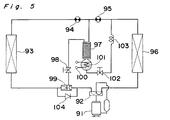
- Fig. 5 illustrates the fourth preferred embodiment of the present invention, in which the heat pump system comprises a main heat pump circuit including a compressor 91, a 4-way valve assembly 92, a utility-side heat exchanger 93 (acting as a condenser during a heating operation), a second throttling device 94, a first throttling device 95 and a source-side heat exchanger 96 (acting as an evaporator during the heating operation), all fluid-connected in a manner shown therein.
- Reference numeral 97 represents a fractionating separator filled with a filling material.
- This fractionating separator 97 has an upper end fluid-connected with a piping connecting the second and first throttling devices 94 and 95 and also through the shut-off valve 98 with a suction port of a coolant ejector 99 disposed between the 4-way valve assembly 92 and the utility-side heat exchanger 93.
- the fractionating separator 97 also has disposed therebelow a reservoir 101 having a heater 100 built therein. The bottom of the reservoir 101 is fluid-connected through a shut-off valve 102 and a pressure reducer 103 with a piping connecting the source-side heat exchanger 96 and the second throttling device 95 together.
- a check valve 104 for bypassing the coolant ejector 99 during the cooling operation is connected parallel to the coolant ejector 99.
- the main fluid circuit operates with the composition of the mixed coolant rich of a high boiling point coolant as filled therein.
- a low boiling point coolant contained in the coolant within the reservoir 101 is, during the heating operation, evaporated by the heater 100 and ascends upwardly within the interior of the fractionating separator 97.
- a portion of the liquid coolant condensed in the utility-side heat exchanger 93 is, after having been reduced in pressure by the second throttling device 94 to the intermediate value, divided and supplied to the upper end of the fractionating separator 97 and, as a result thereof, the fractionating takes place inside the fractionating separator 97 by the effect of a gas-liquid contact, the consequence of which is that the ascending gaseous medium becomes rich of the low boiling point coolant while the descending gaseous medium becomes rich of the high boiling point coolant, leaving the high boiling point coolant to be stored in the reservoir 101 in the form of a condensed liquid.
- the ascending gaseous medium rich of the low boiling point coolant is guided to the suction port of the coolant ejector 99 disposed between the 4-way valve assembly 92 and the utility-side heat exchanger 93.
- the suction effect achieved by the coolant ejector 99 the fractionating can be promoted and the amount of heat produced by the heater 100 can be effectively utilized at the time the gaseous medium rich of the low boiling point coolant flows into the utility-side heat exchanger 93 in readiness for the subsequent condensation thereof.
- the main fluid circuit can be operated with the mixed coolant rich of the low boiling point coolant.
- the low boiling contained in the coolant within the reservoir 101 is mainly evaporated by the heater 100 and ascends upwardly within the interior of the fractionating separator 97.
- a portion of the liquid coolant condensed in the source-side heat exchanger 96 is, after having been reduced in pressure by the first throttling device 95 to the intermediate value, divided and supplied to the upper end of the fractionating separator 97 and, as a result thereof, the fractionating takes place inside the fractionating separator 97 by the effect of a gas-liquid contact, the consequence of which is that the ascending gaseous medium becomes rich of the low boiling point coolant while the descending gaseous medium becomes rich of the high boiling point coolant, leaving the high boiling point coolant to be stored in the reservoir 101 in the form of a condensed liquid.
- the ascending gaseous medium rich of the low boiling point coolant is guided to the suction port of the coolant ejector 99, disposed between the 4-way valve assembly 92 and the utility-side heat exchanger 93, and then to the suction side of the compressor 91 through the 4-way valve assembly 92. Therefore, no increase of a loss of pressure occur which would otherwise occur when flowing into the utility-side heat exchanger 93 acting as an evaporator. In this way, the main fluid circuit can be operated with the mixed coolant rich of the low boiling point coolant.
- the check valve 104 is employed and connected parallel to the coolant ejector 99 for bypassing the coolant ejector 99, the coolant ejector 99 will not constitute a cause of the loss of pressure during the cooling operation.
- the heater 100 should be turned off and the shut-off valves 98 and 102 should be closed and opened, respectively.
- the high boiling point coolant in the reservoir 101 flows into the main fluid circuit to make the mixed coolant in the main fluid circuit rich of the high boiling point coolant as filled therein.
- a high temperature heat source in a refrigerating cycle such as, for example, a discharge piping of the compressor 91 may be employed.
- the load which would be imposed on the source-side heat exchanger 96 acting as the condenser during the cooling operation can be advantageously reduced, and, in the case where the fractionating separator 97 is desired to be maintained at the intermediate pressure, the heating temperature afforded by the heater 100 can be advantageously lowered.
Landscapes
- Engineering & Computer Science (AREA)
- Physics & Mathematics (AREA)
- Mechanical Engineering (AREA)
- Thermal Sciences (AREA)
- General Engineering & Computer Science (AREA)
- Compression-Type Refrigeration Machines With Reversible Cycles (AREA)
Description
- The present invention relates to a heat pump system operable with the use of a non-azeotropic mixed coolant and capable of changing the composition of the non-azeotropic mixed coolant while storing a high boiling point coolant separated from the non-azeotropic mixed coolant.
- In US-A-2938362, a multiple fluid refrigerating system is disclosed which comprises a compressor, a condenser, an expansion valve as throttling device and an evaporator. Furthermore, a rectifier is provided and has an upper end fluid-connected with the exit side of the condenser. A reservoir portion is disposed beneath the rectifier and has a bottom fluid-connected through a valve to the inlet side of the evaporator. Moreover, a heater is provided for heating the coolant in the reservoir.
- The prior art heat pump system of the construction described above is selectively operable in one of the two modes; the non-fractionating mode in which the system operates with the mixed coolant filled therein without altering the composition thereof, and the fractionating mode in which, while a high boiling point coolant is stored, the system operates with the composition rich of a low boiling point coolant. Hereinafter, the method practiced by the prior art system for changing the composition of the non-azeotropic mixed coolant filled therein will be described.
- During the non-fractionating mode, and when the heater is turned off, the reservoir merely stores an excessive coolant and, during the closure of the valve, it stores the coolant, but during the opening of the valve, the coolant is in part stored and in part passed to the evaporator through the pressure reducer. Accordingly, the main fluid circuit operates with the mixed coolant whose composition is rich of a high boiling point coolant filled in the system.
- On the other hand, during the fractionating mode, and when the valve is closed and the heater is turned on, a low boiling point coolant contained in the coolant stored in the reservoir is evaporated to pass upwardly through the interior of the fractionating separator. At this time, a liquid coolant is supplied from the exhibit of the condenser by way of a piping to the rectifier in which fractionating takes place by the effect of a gas-liquid contact so that the gaseous medium which ascends becomes rich of the low boiling point coolant while the gaseous medium which descends becomes rich of the high boiling point cooling, allowing the high boiling point coolant to be stored in the reservoir in the form of a condensed liquid. The ascending gaseous medium rich of the low boiling point coolant flows into the main fluid circuit which now operates with the composition rich of the low boiling point coolant.
- The heat pump system of such a composition-variable type is applied in, for example, a hot-water supply system and is ususally operated with the filled composition rich of the high boiling point coolant so that, during the use thereof, a hot water can be available. Where the hot water is stored in a time as short as possible, the heat pump system can be operated with the composition rich of the low boiling point coolant having a high heating capability.
- However, the prior art heat pump system of the above described type has a problem in that, since the fractionating is carried out by the use of the heater, the energy conversion efficiency tends to be lowered at the time the composition is changed. In other words, the amount of heat produced by the heater is merely utilized for the production of the gaseous medium for the fractionating and, for example, no utilization by the heat recovery to the site of use where hot water is actually utilized is effected.
- Accordingly, the present invention has for its essential object to provide a refrigerating cycle system wherein the amount of heat utilized for the production of the gaseous medium can be effectively utilized and wherein the fractionating can be promoted.
- To achieve the above object, the present invention provides a heat pump system which comprises:
a main heat pump circuit filled with non-azeotropic mixed coolant and including a compressor, a utility-side heat exchanger, a throttling device, a source heat exchanger, a fractionating separator having an upper end fluid-connected with an exit side of the utility-side heat exchanger, and a reservoir disposed beneath the fractionating separator and having a bottom fluid-connected through a shut-off valve to the inlet side of the fource-side heat exchanger characterized by a low pressure piping connected between the shut-off valve and the inlet side of the fource-side heat exchanger, and a coolant ejector disposed between the compressor and the utility-side heat exchanger, wherein a gaseous medium generated from the fractionating separator when the reservoir is heated is guided to a suction port of the coolant ejector to flow into the main heat pump circuit. - According to the present invention the coolant ejector is provided upstream of a utility-side heat exchanger (condenser) with respect to the direction of flow of the coolant and has a suction port fluid-connected with the upper end of the fractionating separator so that, during the fractionating mode, the low boiling point coolant contained in the coolant stored in the reservoir can be mainly evaporated by the heater and the resultant gaseous medium rich of the low boiling point coolant ascending through the interior of the fractionating separator is guided to a suction port of a coolant ejector disposed upstream of the condenser, wherefore the amount of heat produced by the heater can be effectively utilized when the gaseous medium is fed back to the condenser for condensation thereof.
- This and other objects and features of the present invention will become apparent from the following description taken in conjunction with preferred embodiments thereof with reference to the accompanying drawings, in which:
- Fig. 1 is a schematic fluid circuit diagram showing a heat pump system wherein a coolant ejector is provided upstream of the utility-side heat exchanger (condenser) according to the present invention;
- Fig. 2 is a schematic fluid circuit diagram showing one embodiment of the heat pump system capable of being operated selectively for heating and cooling according to the present invention;
- Fig. 3 is a schematic fluid circuit diagram showing another embodiment of the heat pump system capable of being operated selectively for heating and cooling according to the present invention;
- Fig. 4 is a schematic fluid circuit diagram showing a further embodiment of the heat pump system capable of being operated selectively for heating and cooling according to the present invention; and
- Fig. 5 is a schematic fluid circuit diagram showing a still further embodiment of the heat pump system capable of being operated selectively for heating and cooling according to the present invention.
- Referring first to Fig. 1, a heat pump system according to a first embodiment of the present invention comprises a main fluid circuit including a
compressor 11, a utility-side heat exchanger (condenser) 12, athrottling device 13 and a source-side heat exchanger (evaporator) 14, all fluid-connected in a manner as shown. A fractionatingseparator 15 has an upper end fluid-connected with an outlet of the utility-side heat exchanger 12 and also with a suction port of acoolant ejector 16 disposed upstream of the utility-side heat exchanger 12 with respect to the direction of flow of medium, that is, on one side adjacent an inlet of the utility-side heat exchanger 12. The fractionatingseparator 15 has disposed therebelow areservoir 18 having aheater 17 built therein, the bottom of saidreservoir 18 being fluid connected with the source-side heat exchanger 14 through a shut-offvalve 19 and a pressure reducer 20. - A method of varying the composition of the non-azeotropic mixed coolant filled in the heat pump system will now be described. In the first place, during the non-fractionating mode, when the
heater 17 is turned off and the shut-offvalve 19 is opened, an excessive coolant is stored in thereservoir 18, a portion of which flows to the source-side heat exchanger 14 through the pressure reducer 20, and, accordingly, the heat pump system operates with the composition of the mixed coolant rich of a high boiling point coolant as filled therein. - During the fractionating mode, when the
heater 17 is turned on and the shut-offvalve 19 is closed, a low boiling point coolant contained in the coolant within thereservoir 18 is mainly evaporated and ascends upwardly within the interior of the fractionatingseparator 15. At this time, a liquid coolant is supplied from an exit of the utility-side heat exchanger 12 to the upper end of the fractionatingseparator 15 and, as a result thereof, the fractionating takes place inside the fractionatingseparator 15 by the effect of a gas-liquid contact, the consequence of which is that the ascending gaseous medium becomes rich of the low boiling point coolant while the descending gaseous medium becomes rich of the high boiling point coolant, leaving the high boiling point coolant to be stored in thereservoir 18 in the form of a condensed liquid. On the other hand, the ascending gaseous medium rich of the low boiling point coolant is guided to the suction port of thecoolant ejector 15 disposed upstream of the utility-side heat exchanger 12 and, therefore, the amount of heat produced by the heater can be effectively utilized at the time the gaseous medium rich of the low boiling point coolant flows into the utility-side heat exchanger 12 in readiness for the subsequent condensation thereof. Thus, the main fluid circuit can be operated with the mixed coolant rich of the low boiling point coolant. - Where the composition in the main fluid circuit is desired to be restored to the original one, the
heater 17 should be turned off and the shut-offvalve 19 should be opened. In such case, the high boiling point coolant in thereservoir 18 flows into the main fluid circuit to make the mixed coolant in the main fluid circuit rich of the high boiling point coolant as filled therein. - It is to be noted that, in place of the
heater 17, a high temperature heat source in a refrigerating cycle such as, for example, a discharge piping of thecompressor 11 may be employed. - In the embodiment shown in Fig. 2, the heat pump system shown therein comprises a main heat pump circuit including a
compressor 31, a 4-way valve assembly 32, a utility-side heat exchanger 33 (acting as a condenser during a heating operation), athrottling device 34 and a source-side heat exchanger 35 (acting as an evaporator during the heating operation), all fluid-connected in a manner shown therein. Reference numeral 36 represents a fractionating separator filled with a filling material. This fractionating separator 36 has an upper end fluid-connected through afirst check valve 37 with a piping connecting thethrottling device 34 and the utility-side heat exchanger 33 together and has disposed therebelow areservoir 39 having aheater 38 built therein. The bottom of thereservoir 39 is fluid connected through a shut-off valve 40 and a pressure reducer 41 with a piping connecting the source-side heat exchanger 35 and the throttling device 24 together. The upper end of the fractionating separator 36 is also fluid-connected through asecond check valve 42 to a suction port of acoolant ejector 43 which is disposed between thecompressor 31 and the 4-way valve assembly 32. With this arrangement, the fractionating separator 36 can be connected to a high pressure side of the main fluid circuit during the heating operation and to a low pressure side of the main fluid circuit during a cooling operation. - A method of varying the composition of the non-azeotropic mixed coolant filled in the heat pump system will now be described. In the first place, during the non-fractionating mode, when the
heater 38 is turned off and the shut-off valve 40 is opened, a portion of the coolant condensed in the utility-side heat exchanger 33 is, during the heating operation, divided, one component flowing through the fractionating separator 36 into the reservoir for the storage therein as an excessive coolant and the other component flowing through the shut-off calve 40 and then through the pressure reducer 41 to the source-side heat exchanger 35, and, accordingly, the heat pump system operates with the composition of the mixed coolant rich of a high boiling point coolant as filled therein. During the cooling operation, however, a portion of the coolant condensed in the source-side heat exchanger 35 is divided, one component flowing through thepressure reducer 41 and then through the shut-off valve 40 into thereservoir 39 for the storage therein as an excessive coolant and the other component flowing upwardly out from the fractionating separator 36 to the utility-side heat exchanger 33 and, accordingly, the heat pump system operates with the composition of the mixed coolant rich of a high boiling point coolant as filled therein. - During the fractionating mode taking place during the heating operation, when the
heater 38 is turned on and the shut-off valve 40 is closed, a low boiling point coolant contained in the coolant within thereservoir 39 is mainly evaporated by theheater 38 and ascends upwardly within the interior of the fractionating separator 36. At this time, a portion of the liquid coolant condensed in the utility-side heat exchanger 33 is divided and supplied from an exit of the utility-side heat exchanger 33 to the upper end of the fractionating separator 36 and, as a result thereof, the fractionating takes place inside the fractionating separator 36 by the effect of a gas-liquid contact, the consequence of which is that the ascending gaseous medium becomes rich of the low boiling point coolant while the descending gaseous medium becomes rich of the high boiling point coolant, leaving the high boiling point coolant to be stored in thereservoir 39 in the form of a condensed liquid. On the other hand, the ascending gaseous medium rich of the low boiling point coolant is guided through thesecond check valve 42 to the suction port of thecoolant ejector 43 disposed between thecompressor 31 and the 4-way valve assembly 32. By the suction effect achieved by thecoolant ejector 43, the fractionating can be promoted and the amount of heat produced by theheater 38 can be effectively utilized at the time the gaseous medium rich of the low boiling point coolant flows into the utility-side heat exchanger 33 in readiness for the subsequent condensation thereof. Thus, the main fluid circuit can be operated with the mixed coolant rich of the low boiling point coolant. - During the fractionating mode taking place during the cooling operation, when the
heater 38 is turned on and the shut-off valve 40 is closed, the low boiling contained in the coolant within thereservoir 39 is mainly evaporated by theheater 38 and ascends upwardly within the interior of the fractionating separator 36. At this time, a portion of the liquid coolant condensed in the source-side heat exchanger 35 and expanded by thethrottling device 34 to a vapor pressure at which vaporization takes place is divided and supplied to the upper end of the fractionating separator 36 and, as a result thereof, the fractionating takes place inside the fractionating separator 36 by the effect of a gas-liquid contact, the consequence of which is that the ascending gaseous medium becomes rich of the low boiling point coolant while the descending gaseous medium becomes rich of the high boiling point coolant, leaving the high boiling point coolant to be stored in thereservoir 39 in the form of a condensed liquid. On the other hand, the ascending gaseous medium rich of the low boiling point coolant is guided through thefirst check valve 37 to join the coolant then flowing through the main fluid circuit and then flows into the utility-side heat exchanger 33. In this way, the main fluid circuit can be operated with the mixed coolant rich of the low boiling point coolant. Thus, during the cooling operation the fractionating separator 36 is connected to the low pressure side of the main fluid circuit and, therefore, the temperature afforded by theheater 38 may be relatively low. - Where the composition in the main fluid circuit is desired to be restored to the original one, the
heater 38 should be turned off and the shut-off valve 40 should be opened. In such case, the high boiling point coolant in thereservoir 18 flows into the main fluid circuit to make the mixed coolant in the main fluid circuit rich of the high boiling point coolant as filled therein. - It is to be noted that, in place of the
heater 38, a high temperature heat source in a refrigerating cycle such as, for example, a discharge piping of thecompressor 31 may be employed. In such case, the load which would be imposed on the source-side heat exchanger acting as the condenser during the cooling operation can be advantageously reduced. - In the embodiment shown in Fig. 3, the heat pump system shown therein comprises a main heat pump circuit including a
compressor 51, a 4-way valve assembly 52, a utility-side heat exchanger 53 (acting as a condenser during a heating operation), athrottling device 54 and a source-side heat exchanger 55 (acting as an evaporator during the heating operation), all fluid-connected in a manner shown therein.Reference numeral 56 represents a fractionating separator filled with a filling material. This fractionatingseparator 56 has an upper end fluid-connected through afirst pressure reducer 57 with a piping connecting thethrottling device 54 and the utility-side heat exchanger 53 together and, also, through a first shut-offvalve 58 with a piping connecting the source-side heat exchanger 55 and thethrottling device 54 together. Areservoir 60 having aheater 59 built therein is disposed below the fractionatingseparator 56, the bottom of saidreservoir 60 being fluid-connected through asecond pressure reducer 61 and then through a second shut-offvalve 62 with the piping connecting the source-side heat exchanger 55 and thethrottling device 54 together. Acoolant ejector 63 is disposed between thecompressor 51 and the 4-way valve assembly 52, having a suction port fluid connected with the upper end of thefractionating separator 56 through afirst check valve 64. In parallel relation with thefirst pressure reducer 57, asecond check valve 65 is connected and is operable to allow the passage of the coolant therethrough towards the fractionatingseparator 56. - A method of varying the composition of the non-azeotropic mixed coolant filled in the heat pump system will now be described. In the first place, during the non-fractionating mode, when the
heater 59 is turned off, the shut-offvalve 58 is opened and the second shut-offvalve 62 is opened, a portion of the coolant condensed in the utility-side heat exchanger 53 is, during the heating operation, divided, one component flowing through thesecond check valve 65 and thefractionating separator 56 into thereservoir 60 for the storage therein as an excessive coolant and the other component flowing through thesecond pressure reducer 61 and the second shut-off calve 62 to the source-side heat exchanger 55, and, accordingly, the main fluid circuit operates with the composition of the mixed coolant rich of a high boiling point coolant as filled therein. During the cooling operation, however, a portion of the coolant condensed in the source-side heat exchanger 55 is divided, one component flowing through the second shut-offvalve 62 and thesecond pressure reducer 61 into thereservoir 60 for the storage therein as an excessive coolant and the other component flowing upwardly out from the fractionatingseparator 56 through thefirst pressure reducer 57 to the utility-side heat exchanger 53 and, accordingly, the main fluid circuit operates with the composition of the mixed coolant rich of a high boiling point coolant as filled therein. - During the fractionating mode taking place during the heating operation, when the
heater 59 is turned on and the first and second shut-offvalves reservoir 60 is mainly evaporated by theheater 59 and ascends upwardly within the interior of thefractionating separator 56. At this time, a portion of the liquid coolant condensed in the utility-side heat exchanger 53 is divided and a portion thereof is supplied through thesecond check valve 65 to the upper end of thefractionating separator 56 and, as a result thereof, the fractionating takes place inside the fractionatingseparator 56 by the effect of a gas-liquid contact, the consequence of which is that the ascending gaseous medium becomes rich of the low boiling point coolant while the descending gaseous medium becomes rich of the high boiling point coolant, leaving the high boiling point coolant to be stored in thereservoir 60 in the form of a condensed liquid. On the other hand, the ascending gaseous medium rich of the low boiling point coolant is guided to the suction port of thecoolant ejector 63 disposed between thecompressor 51 and the 4-way valve assembly 52. By the suction effect achieved by thecoolant ejector 63, the fractionating can be promoted and the amount of heat produced by theheater 58 can be effectively utilized at the time the gaseous medium rich of the low boiling point coolant flows into the utility-side heat exchanger 53 in readiness for the subsequent condensation thereof. Thus, the main fluid circuit can be operated with the mixed coolant rich of the low boiling point coolant. - During the fractionating mode taking place during the cooling operation, when the
heater 59 is turned on and the first and second shut-offvalves reservoir 60 is mainly evaporated by theheater 59 and ascends upwardly within the interior of thefractionating separator 56. At this time, a portion of the liquid coolant condensed in the source-side heat exchanger 55 is divided and supplied through the first shut-offvalve 58 to the upper end of thefractionating separator 56 and, as a result thereof, the fractionating takes place inside the fractionatingseparator 56 by the effect of a gas-liquid contact, the consequence of which is that the ascending gaseous medium becomes rich of the low boiling point coolant while the descending gaseous medium becomes rich of the high boiling point coolant, leaving the high boiling point coolant to be stored in thereservoir 59 in the form of a condensed liquid. On the other hand, the ascending gaseous medium rich of the low boiling point coolant is guided through thefirst pressure reducer 57 into the utility-side heat exchanger 53. In this way, the main fluid circuit can be operated with the mixed coolant rich of the low boiling point coolant. - Where the composition in the main fluid circuit is desired to be restored to the original one, the
heater 59 should be turned off and both of the first and second shut-offvalves reservoir 60 lows into the main fluid circuit to make the mixed coolant in the main fluid circuit rich of the high boiling point coolant as filled therein. - It is to be noted that, in place of the
heater 58, a high temperature heat source in a refrigerating cycle such as, for example, a discharge piping of thecompressor 51 may be employed. In such case, the load which would be imposed on the source-side heat exchanger 55 acting as the condenser during the cooling operation can be advantageously reduced. - In the embodiment shown in and described with reference to Fig. 3, the
second check valve 65 has been used and connected parallel to thefirst pressure reducer 57 so that, during the heating operation, the fractionatingseparator 56 can be retained at a high pressure (condensing pressure) and the pressure of the low boiling point coolant gas to be sucked into thecoolant ejector 63 can be increased, thereby enabling thecheck valve 64 to be get rid of. However, the present invention can be equally applicable to the case wherein nosecond check valve 65 is employed, in which case the low boiling point gaseous coolant to be sucked into thecoolant ejector 63 may attain an intermediate pressure, however, the system of the present invention can work satisfactorily. - Also, the first shut-off
valve 58 may be constituted by a pressure reducer and a check valve, and by the sucking power of thecoolant ejector 63, the low boiling point gaseous coolant produced during the fractionating mode taking place during the heating operation can be sufficiently sucked towards a discharge side of the compressor. - Fig. 4 illustrates the third preferred embodiment of the present invention, in which the heat pump system comprises a main heat pump circuit including a
compressor 71, a 4-way valve assembly 72, a utility-side heat exchanger 73 (acting as a condenser during a heating operation), athrottling device 74 and a source-side heat exchanger 75 (acting as an evaporator during the heating operation), all fluid-connected in a manner shown therein.Reference numeral 76 represents a fractionating separator filled with a filling material. This fractionatingseparator 76 has an upper end fluid-connected with a piping connecting thethrottling device 74 and the utility-side heat exchanger 73 together and has disposed therebelow areservoir 78 having aheater 77 built therein. The bottom of thereservoir 78 is fluid connected through a shut-offvalve 79 and apressure reducer 80 with a piping connecting the source-side heat exchanger 75 and the throttling device 24 together. The upper end of thefractionating separator 76 is also fluid-connected through afirst check valve 81 to a suction port of acoolant ejector 82 which is disposed between the 4-way valve assembly 72 and the utility-side heat exchanger 73.Reference numeral 83 represents a second check valve for bypassing thecoolant ejector 82 during the cooling operation. - A method of varying the composition of the non-azeotropic mixed coolant filled in the heat pump system will now be described. In the first place, during the non-fractionating mode, when the
heater 77 is turned off and the shut-offvalve 79 is opened, a portion of the coolant condensed in the utility-side heat exchanger 73 is, during the heating operation, divided, one component flowing through the fractionatingseparator 76 into thereservoir 78 for the storage therein as an excessive coolant and the other component flowing through the shut-off calve 79 and then through thepressure reducer 80 to the source-side heat exchanger 75, and, accordingly, the heat pump system operates with the composition of the mixed coolant rich of a high boiling point coolant as filled therein. During the cooling operation, however, a portion of the coolant condensed in the source-side heat exchanger 75 is divided, one component flowing through thepressure reducer 80 and then through the shut-offvalve 79 into thereservoir 78 for the storage therein as an excessive coolant and the other component flowing upwardly out from the fractionatingseparator 76 to the utility-side heat exchanger 73 and, accordingly, the heat pump system operates with the composition of the mixed coolant rich of a high boiling point coolant as filled therein. - During the fractionating mode taking place during the heating operation, when the
heater 77 is turned on and the shut-offvalve 79 is closed, a low boiling point coolant contained in the coolant within thereservoir 78 is mainly evaporated by theheater 77 and ascends upwardly within the interior of thefractionating separator 76. At this time, a portion of the liquid coolant condensed in the utility-side heat exchanger 73 is divided and supplied to the upper end of thefractionating separator 76 and, as a result thereof, the fractionating takes place inside the fractionatingseparator 76 by the effect of a gas-liquid contact, the consequence of which is that the ascending gaseous medium becomes rich of the low boiling point coolant while the descending gaseous medium becomes rich of the high boiling point coolant, leaving the high boiling point coolant to be stored in thereservoir 78 in the form of a condensed liquid. On the other hand, the ascending gaseous medium rich of the low boiling point coolant is guided to the suction port of thecoolant ejector 82 disposed between thecompressor 71 and the 4-way valve assembly 72. By the suction effect achieved by thecoolant ejector 82, the fractionating can be promoted and the amount of heat produced by theheater 77 can be effectively utilized at the time the gaseous medium rich of the low boiling point coolant flows into the utility-side heat exchanger 73 in readiness for the subsequent condensation thereof. Thus, the main fluid circuit can be operated with the mixed coolant rich of the low boiling point coolant. - During the fractionating mode taking place during the cooling operation, when the
heater 77 is turned on and the shut-offvalve 79 is closed, the low boiling contained in the coolant within thereservoir 78 is mainly evaporated by theheater 77 and ascends upwardly within the interior of thefractionating separator 76. At this time, a portion of the liquid coolant condensed in the source-side heat exchanger 75 and expanded by the throttlingdevice 74 to a vapor pressure at which vaporization takes place is divided and supplied to the upper end of thefractionating separator 76 and, as a result thereof, the fractionating takes place inside the fractionatingseparator 76 by the effect of a gas-liquid contact, the consequence of which is that the ascending gaseous medium becomes rich of the low boiling point coolant while the descending gaseous medium becomes rich of the high boiling point coolant, leaving the high boiling point coolant to be stored in thereservoir 79 in the form of a condensed liquid. On the other hand, the ascending gaseous medium rich of the low boiling point coolant is guided to the suction port of thecoolant ejector 82 through thefirst check valve 81 and then to join the coolant then flowing through the main fluid circuit, finally flowing into thecompressor 71. In this way, the main fluid circuit can be operated with the mixed coolant rich of the low boiling point coolant. - Where the composition in the main fluid circuit is desired to be restored to the original one, the
heater 77 should be turned off and the shut-offvalve 79 should be opened. In such case, the high boiling point coolant in thereservoir 78 flows into the main fluid circuit to make the mixed coolant in the main fluid circuit rich of the high boiling point coolant as filled therein. - According to the embodiment shown in and described with reference to Fig. 4, for the purpose of fractionating separation, only during the heating operation in which the recovery of the amount of heat consumed by the
heater 77 may bring about effective results, thecoolant ejector 82 is operated, but during the cooling operation in which the amount of heat consumed by theheater 77 need not be recovered, the gaseous coolant rich of the low boiling point coolant flowing out from the upper end of thefractionating separator 76 is guided so as to bypass the utility-side heat exchanger 73, which acts as an evaporator, and then into the suction side of thecompressor 71. Therefore, any possible increase of a loss of pressure in the evaporator can be minimized and, at the same time, since the coolant flowing through the main fluid circuit can bypass thecoolant ejector 82, thecoolant ejector 82 can be prevented from constituting a cause of the loss of pressure. - Fig. 5 illustrates the fourth preferred embodiment of the present invention, in which the heat pump system comprises a main heat pump circuit including a
compressor 91, a 4-way valve assembly 92, a utility-side heat exchanger 93 (acting as a condenser during a heating operation), asecond throttling device 94, afirst throttling device 95 and a source-side heat exchanger 96 (acting as an evaporator during the heating operation), all fluid-connected in a manner shown therein.Reference numeral 97 represents a fractionating separator filled with a filling material. This fractionatingseparator 97 has an upper end fluid-connected with a piping connecting the second andfirst throttling devices valve 98 with a suction port of acoolant ejector 99 disposed between the 4-way valve assembly 92 and the utility-side heat exchanger 93. The fractionatingseparator 97 also has disposed therebelow areservoir 101 having aheater 100 built therein. The bottom of thereservoir 101 is fluid-connected through a shut-offvalve 102 and apressure reducer 103 with a piping connecting the source-side heat exchanger 96 and thesecond throttling device 95 together. Acheck valve 104 for bypassing thecoolant ejector 99 during the cooling operation is connected parallel to thecoolant ejector 99. - A method of varying the composition of the non-azeotropic mixed coolant filled in the heat pump system will now be described. In the first place, during the non-fractionating mode, when the
heater 100 is turned off and the shut-offvalves side heat exchanger 93 and reduced in pressure by thesecond throttling device 94 to an intermediate value is, during the heating operation, divided, one component flowing through the fractionatingseparator 97 into thereservoir 101 for the storage therein as an excessive coolant and the other component flowing through the shut-offvalve 102 and then through thepressure reducer 103 to the source-side heat exchanger 96, and, accordingly, the main fluid circuit operates with the composition of the mixed coolant rich of a high boiling point coolant as filled therein. During the cooling operation, however, a portion of the coolant condensed in the source-side heat exchanger 96 is divided, one component flowing through thepressure reducer 103 and then through the shut-offvalve 102 into thereservoir 101 for the storage therein as an excessive coolant and the remaining component flowing upwardly out from the upper end of thefractionating separator 97 and then through thesecond throttling device 94 to the utility-side heat exchanger 93 and, accordingly, the main fluid circuit operates with the composition of the mixed coolant rich of a high boiling point coolant as filled therein. - During the fractionating mode, when the
heater 100 is turned on and the shut-offvalves reservoir 101 is, during the heating operation, evaporated by theheater 100 and ascends upwardly within the interior of thefractionating separator 97. At this time, a portion of the liquid coolant condensed in the utility-side heat exchanger 93 is, after having been reduced in pressure by thesecond throttling device 94 to the intermediate value, divided and supplied to the upper end of thefractionating separator 97 and, as a result thereof, the fractionating takes place inside the fractionatingseparator 97 by the effect of a gas-liquid contact, the consequence of which is that the ascending gaseous medium becomes rich of the low boiling point coolant while the descending gaseous medium becomes rich of the high boiling point coolant, leaving the high boiling point coolant to be stored in thereservoir 101 in the form of a condensed liquid. On the other hand, the ascending gaseous medium rich of the low boiling point coolant is guided to the suction port of thecoolant ejector 99 disposed between the 4-way valve assembly 92 and the utility-side heat exchanger 93. By the suction effect achieved by thecoolant ejector 99, the fractionating can be promoted and the amount of heat produced by theheater 100 can be effectively utilized at the time the gaseous medium rich of the low boiling point coolant flows into the utility-side heat exchanger 93 in readiness for the subsequent condensation thereof. Thus, the main fluid circuit can be operated with the mixed coolant rich of the low boiling point coolant. - During the cooling operation, the low boiling contained in the coolant within the
reservoir 101 is mainly evaporated by theheater 100 and ascends upwardly within the interior of thefractionating separator 97. At this time, a portion of the liquid coolant condensed in the source-side heat exchanger 96 is, after having been reduced in pressure by thefirst throttling device 95 to the intermediate value, divided and supplied to the upper end of thefractionating separator 97 and, as a result thereof, the fractionating takes place inside the fractionatingseparator 97 by the effect of a gas-liquid contact, the consequence of which is that the ascending gaseous medium becomes rich of the low boiling point coolant while the descending gaseous medium becomes rich of the high boiling point coolant, leaving the high boiling point coolant to be stored in thereservoir 101 in the form of a condensed liquid. On the other hand, the ascending gaseous medium rich of the low boiling point coolant is guided to the suction port of thecoolant ejector 99, disposed between the 4-way valve assembly 92 and the utility-side heat exchanger 93, and then to the suction side of thecompressor 91 through the 4-way valve assembly 92. Therefore, no increase of a loss of pressure occur which would otherwise occur when flowing into the utility-side heat exchanger 93 acting as an evaporator. In this way, the main fluid circuit can be operated with the mixed coolant rich of the low boiling point coolant. - Also, since the
check valve 104 is employed and connected parallel to thecoolant ejector 99 for bypassing thecoolant ejector 99, thecoolant ejector 99 will not constitute a cause of the loss of pressure during the cooling operation. - Where the composition in the main fluid circuit is desired to be restored to the original one, the
heater 100 should be turned off and the shut-offvalves reservoir 101 flows into the main fluid circuit to make the mixed coolant in the main fluid circuit rich of the high boiling point coolant as filled therein. - It is to be noted that, in place of the
heater 100, a high temperature heat source in a refrigerating cycle such as, for example, a discharge piping of thecompressor 91 may be employed. In such case, the load which would be imposed on the source-side heat exchanger 96 acting as the condenser during the cooling operation can be advantageously reduced, and, in the case where thefractionating separator 97 is desired to be maintained at the intermediate pressure, the heating temperature afforded by theheater 100 can be advantageously lowered.
Claims (9)
- A heat pump system which comprises:
a main heat pump circuit filled with non-azeotropic mixed coolant and including a compressor (11; 31; 51; 71; 91), a utility-side heat exchanger (12; 33; 53; 75; 93), a throttling device (13; 34; 54; 74; 95), a source heat exchanger (14; 35; 55; 75; 96);
a fractionating separator (15; 36; 56; 76; 97) having an upper end fluid-connected with an exit side of the utility-side heat exchanger (12; 33; 53; 73; 93); and
a reservoir (18; 39; 60; 78; 101) disposed beneath the fractionating separator (15; 36; 56; 76; 97) and having a bottom fluid-connected through a shut-off valve (19; 40; 62; 79; 102) to the inlet side of the source-side heat exchanger (14; 35; 55; 75; 96)
characterized by
a low pressure piping (20; 41; 61; 80; 103) connected between the shut-off valve (19; 40; 62; 79; 102) and the inlet side of the source-side heat exchanger (14; 35; 55; 75; 96); and
a coolant ejector (16; 43; 63; 82; 99) disposed between the compressor (11; 31; 51; 71; 91) and the utility-side heat exchanger (12; 33; 53; 73; 93), wherein a gaseous medium generated from the fractionating separator (15; 36; 56; 76; 97) when the reservoir (18; 39; 60; 78; 101) is heated is guided to a suction port of the coolant ejector (16; 43; 63; 82; 99) to flow into the main heat pump circuit. - The heat pump system as claimed in Claim 1, further comprising a four-way valve assembly (32; 52) disposed between any one of the utility-side (33; 53) and source-side heat exchanger (35; 55) and the compressor (31; 51), and wherein said coolant ejector (43; 63) is disposed between the compressor (31; 51) and the four-way valve assembly (32; 52) with the suction port thereof fluid-connected with the upper end of the fractionating separator (36; 56) such that, during the main heat pump circuit set in a heating operation and in a cooling operation, said utility-side heat exchanger (33; 53) acts as a condenser and an evaporator, respectively.
- The heat pump system as claimed in Claim 2, further comprising a check valve (42; 64) disposed between the upper end of the fractionating separator (36; 56) and the coolant ejector (43; 63).
- The heat pump system as claimed in Claim 2, further comprising a first check valve (37) through which the upper end of the fractionating separator (36) is fluid-connected with a piping extending between the throttling device (34) and the utility-side heat exchanger (33), and a second check valve (42) through which the upper end of the fractionating separator (36) is fluid-connected with the suction port of the coolant ejector (43), a junction between the first check valve (37) and the throttle valve (34) being connected with the upper end of the fractionating separator (36), and said reservoir (39) being fluid-connected through the shut-off valve (40) with a piping (41) extending between the source-side heat exchanger (35) and the throttling device (34).
- The heat pump system as claimed in Claim 2, further comprising a parallel fluid circuit including a check valve (65) and a pressure reducer (57), the upper end of the fractionating separator (56) being connected through said parallel fluid circuit with a piping extending between the throttling device (54) and the utility-side heat exchanger (53), said upper end of the fractionating separator (56) being coupled with the suction port of the coolant ejector (63) through a check valve (64) and through a shut-off valve (58) with a piping extending between the source-side heat exchanger (55) and the throttling device (54), said reservoir (60) being fluid-connected through the shut-off valve (62) with a piping extending between the source-side heat exchanger (55) and the throttling device (54).
- The heat pump system as claimed in Claim 1, further comprising a four-way valve assembly (72; 92) disposed between any one of the utility-side (73; 92) and source-side heat exchanger (75; 96) and the compressor (71; 91), and wherein said coolant ejector (82; 99) is disposed between the utility-side heat exchanger (73; 93) and the four-way valve assembly (72; 92) with the suction port thereof fluid-connected to the upper end of the fractionating separator (76).
- The heat pump system as claimed in Claim 6, further comprising a check valve (83; 104) disposed parallel to the coolant ejector (82; 99).
- The heat pump system as claimed in Claim 6, further comprising a check valve (81) disposed between the suction port of the coolant ejector (82) and the upper end of the fractionating separator (76).
- The heat pump system as claimed in Claim 1 or 2, further comprising a second throttling device (94) disposed between the utility-side heat exchanger (93) and a junction of the throttling device (95) with the fractionating separator (97), a piping extending between both of the throttling devices (94, 95) being fluid-connected with the upper end of the fractionating separator (97).
Applications Claiming Priority (6)
| Application Number | Priority Date | Filing Date | Title |
|---|---|---|---|
| JP62192949A JPS6438567A (en) | 1987-07-31 | 1987-07-31 | Refrigeration cycle device |
| JP192949/87 | 1987-07-31 | ||
| JP62269632A JPH01111172A (en) | 1987-10-26 | 1987-10-26 | Heat pump device |
| JP269631/87 | 1987-10-26 | ||
| JP269632/87 | 1987-10-26 | ||
| JP62269631A JPH01111171A (en) | 1987-10-26 | 1987-10-26 | heat pump equipment |
Publications (3)
| Publication Number | Publication Date |
|---|---|
| EP0301503A2 EP0301503A2 (en) | 1989-02-01 |
| EP0301503A3 EP0301503A3 (en) | 1990-11-14 |
| EP0301503B1 true EP0301503B1 (en) | 1992-09-30 |
Family
ID=27326694
Family Applications (1)
| Application Number | Title | Priority Date | Filing Date |
|---|---|---|---|
| EP88112126A Expired - Lifetime EP0301503B1 (en) | 1987-07-31 | 1988-07-27 | Heat pump system |
Country Status (4)
| Country | Link |
|---|---|
| US (1) | US4840042A (en) |
| EP (1) | EP0301503B1 (en) |
| KR (1) | KR930000852B1 (en) |
| DE (1) | DE3875006T2 (en) |
Families Citing this family (25)
| Publication number | Priority date | Publication date | Assignee | Title |
|---|---|---|---|---|
| JPH01273959A (en) * | 1988-04-25 | 1989-11-01 | Nippon Denso Co Ltd | Air conditioner for vehicle |
| US5012651A (en) * | 1988-12-28 | 1991-05-07 | Matsushita Electric Industrial Co., Ltd. | Heat pump apparatus |
| US4981023A (en) * | 1989-07-11 | 1991-01-01 | Innovative Products, Inc. | Air conditioning and heat pump system |
| FR2652884B1 (en) * | 1989-10-09 | 1992-10-16 | Air Liquide | METHOD AND INSTALLATION FOR REFRIGERATION USING A REFRIGERANT MIXTURE. |
| HU210994B (en) * | 1990-02-27 | 1995-09-28 | Energiagazdalkodasi Intezet | Heat-exchanging device particularly for hybrid heat pump operated by working medium of non-azeotropic mixtures |
| US5140827A (en) * | 1991-05-14 | 1992-08-25 | Electric Power Research Institute, Inc. | Automatic refrigerant charge variation means |
| US5165254A (en) * | 1991-08-01 | 1992-11-24 | Institute Of Gas Technology | Counterflow air-to-refrigerant heat exchange system |
| US5186012A (en) * | 1991-09-24 | 1993-02-16 | Institute Of Gas Technology | Refrigerant composition control system for use in heat pumps using non-azeotropic refrigerant mixtures |
| US5309732A (en) * | 1992-04-07 | 1994-05-10 | University Of Moncton | Combined cycle air/air heat pump |
| JP2611185B2 (en) * | 1994-09-20 | 1997-05-21 | 佐賀大学長 | Energy conversion device |
| US5551255A (en) * | 1994-09-27 | 1996-09-03 | The United States Of America As Represented By The Secretary Of Commerce | Accumulator distillation insert for zeotropic refrigerant mixtures |
| US5715694A (en) * | 1995-05-26 | 1998-02-10 | Matsushita Electric Industrial Co., Ltd. | Refrigerator controller |
| JP2002081777A (en) | 2000-09-08 | 2002-03-22 | Hitachi Ltd | Refrigeration cycle |
| JP4463466B2 (en) * | 2001-07-06 | 2010-05-19 | 株式会社デンソー | Ejector cycle |
| JP4848608B2 (en) * | 2001-09-12 | 2011-12-28 | 三菱電機株式会社 | Refrigerant circuit |
| JP5502410B2 (en) * | 2009-01-30 | 2014-05-28 | パナソニック株式会社 | Liquid circulation heating system |
| JP5242434B2 (en) * | 2009-01-30 | 2013-07-24 | パナソニック株式会社 | Liquid circulation heating system |
| JP5984706B2 (en) * | 2013-02-07 | 2016-09-06 | 三菱重工工作機械株式会社 | Coolant suction device and machine tool |
| JP6188918B2 (en) * | 2014-03-14 | 2017-08-30 | 三菱電機株式会社 | Refrigeration equipment |
| MX386847B (en) * | 2014-07-01 | 2025-03-19 | Evapco Inc | EVAPORATOR LIQUID PREHEATER FOR REFRIGERANT CHARGE REDUCTION. |
| US20160109160A1 (en) * | 2014-10-15 | 2016-04-21 | General Electric Company | Packaged terminal air conditioner unit |
| US20170003040A1 (en) * | 2015-07-02 | 2017-01-05 | General Electric Company | Packaged terminal air conditioner unit |
| CN113167507B (en) | 2019-02-25 | 2023-03-31 | Ats日本株式会社 | Refrigeration control system and cooling system |
| CN110895066B (en) * | 2019-12-05 | 2020-10-30 | 乐清市泰博恒电子科技有限公司 | A gas-liquid two-phase flow adiabatic shield pump in an air-conditioning refrigeration cycle system |
| US12320569B2 (en) | 2022-11-17 | 2025-06-03 | Copeland Lp | Climate control systems having ejector cooling for use with moderate to high glide working fluids and methods for operation thereof |
Family Cites Families (9)
| Publication number | Priority date | Publication date | Assignee | Title |
|---|---|---|---|---|
| US2938362A (en) * | 1955-09-02 | 1960-05-31 | Borg Warner | Multiple fluid refrigerating system |
| US3152457A (en) * | 1961-10-26 | 1964-10-13 | Martin Marietta Corp | Refrigerating apparatus for continuously producing very low temperatures |
| CH625609A5 (en) * | 1977-12-23 | 1981-09-30 | Sulzer Ag | |
| US4179898A (en) * | 1978-07-31 | 1979-12-25 | General Electric Company | Vapor compression cycle device with multi-component working fluid mixture and method of modulating its capacity |
| JPS57198968A (en) * | 1981-05-29 | 1982-12-06 | Hitachi Ltd | Heat pump type refrigerator |
| US4580415A (en) * | 1983-04-22 | 1986-04-08 | Mitsubishi Denki Kabushiki Kaisha | Dual refrigerant cooling system |
| FR2575812B1 (en) * | 1985-01-09 | 1987-02-06 | Inst Francais Du Petrole | PROCESS FOR PRODUCING COLD AND / OR HEAT USING A NON-AZEOTROPIC MIXTURE OF FLUIDS IN AN EJECTOR CYCLE |
| KR890004867B1 (en) * | 1985-03-25 | 1989-11-30 | 마쯔시다덴기산교 가부시기가이샤 | Haet pump with a reservoir storing higher pressure refrigerante of non-azeotropic mixture |
| JPS62233645A (en) * | 1986-03-31 | 1987-10-14 | 三菱電機株式会社 | Refrigeration cycle |
-
1988
- 1988-07-25 KR KR1019880009337A patent/KR930000852B1/en not_active Expired - Fee Related
- 1988-07-27 EP EP88112126A patent/EP0301503B1/en not_active Expired - Lifetime
- 1988-07-27 DE DE8888112126T patent/DE3875006T2/en not_active Expired - Fee Related
- 1988-07-29 US US07/226,084 patent/US4840042A/en not_active Expired - Lifetime
Also Published As
| Publication number | Publication date |
|---|---|
| US4840042A (en) | 1989-06-20 |
| EP0301503A3 (en) | 1990-11-14 |
| EP0301503A2 (en) | 1989-02-01 |
| DE3875006D1 (en) | 1992-11-05 |
| KR890002623A (en) | 1989-04-11 |
| KR930000852B1 (en) | 1993-02-06 |
| DE3875006T2 (en) | 1993-02-25 |
Similar Documents
| Publication | Publication Date | Title |
|---|---|---|
| US4840042A (en) | Heat pump system | |
| EP0196051B1 (en) | Heat pump with a reservoir storing higher pressure refrigerant of non-azeotropic mixture | |
| KR930004384B1 (en) | Heat-pump apparatus | |
| JPH0745982B2 (en) | Heat pump device | |
| JPH0646118B2 (en) | Heat pump device | |
| JPH0769083B2 (en) | Heat pump device | |
| JPH0440622B2 (en) | ||
| JPS636347A (en) | Refrigeration cycle | |
| JPH0440623B2 (en) | ||
| JPH0531066B2 (en) | ||
| JPH0769084B2 (en) | Heat pump device | |
| JPH058350B2 (en) | ||
| JPH0238870B2 (en) | NETSUHONPUSOCHI | |
| JPS6146847A (en) | Solar heat type hot water feeding device | |
| JPS636346A (en) | Refrigeration cycle | |
| JPS62261864A (en) | Heat pump device | |
| JPH0264367A (en) | heat pump equipment | |
| JPH0364783B2 (en) | ||
| JPH0769082B2 (en) | Heat pump device | |
| JPH0481708B2 (en) | ||
| JPS63156977A (en) | Refrigeration cycle equipment | |
| JPS62245055A (en) | heat pump equipment | |
| JPS58102052A (en) | Heat pump type water heating equipment | |
| JPH02146468A (en) | heat pump equipment | |
| JPH0737856B2 (en) | Heat pump device |
Legal Events
| Date | Code | Title | Description |
|---|---|---|---|
| PUAI | Public reference made under article 153(3) epc to a published international application that has entered the european phase |
Free format text: ORIGINAL CODE: 0009012 |
|
| 17P | Request for examination filed |
Effective date: 19880727 |
|
| AK | Designated contracting states |
Kind code of ref document: A2 Designated state(s): DE FR GB |
|
| PUAL | Search report despatched |
Free format text: ORIGINAL CODE: 0009013 |
|
| AK | Designated contracting states |
Kind code of ref document: A3 Designated state(s): DE FR GB |
|
| 17Q | First examination report despatched |
Effective date: 19910730 |
|
| GRAA | (expected) grant |
Free format text: ORIGINAL CODE: 0009210 |
|
| AK | Designated contracting states |
Kind code of ref document: B1 Designated state(s): DE FR GB |
|
| REF | Corresponds to: |
Ref document number: 3875006 Country of ref document: DE Date of ref document: 19921105 |
|
| ET | Fr: translation filed | ||
| PLBE | No opposition filed within time limit |
Free format text: ORIGINAL CODE: 0009261 |
|
| STAA | Information on the status of an ep patent application or granted ep patent |
Free format text: STATUS: NO OPPOSITION FILED WITHIN TIME LIMIT |
|
| 26N | No opposition filed | ||
| REG | Reference to a national code |
Ref country code: GB Ref legal event code: IF02 |
|
| PGFP | Annual fee paid to national office [announced via postgrant information from national office to epo] |
Ref country code: FR Payment date: 20020709 Year of fee payment: 15 |
|
| PGFP | Annual fee paid to national office [announced via postgrant information from national office to epo] |
Ref country code: GB Payment date: 20020724 Year of fee payment: 15 |
|
| PGFP | Annual fee paid to national office [announced via postgrant information from national office to epo] |
Ref country code: DE Payment date: 20020731 Year of fee payment: 15 |
|
| PG25 | Lapsed in a contracting state [announced via postgrant information from national office to epo] |
Ref country code: GB Free format text: LAPSE BECAUSE OF NON-PAYMENT OF DUE FEES Effective date: 20030727 |
|
| PG25 | Lapsed in a contracting state [announced via postgrant information from national office to epo] |
Ref country code: DE Free format text: LAPSE BECAUSE OF NON-PAYMENT OF DUE FEES Effective date: 20040203 |
|
| GBPC | Gb: european patent ceased through non-payment of renewal fee |
Effective date: 20030727 |
|
| PG25 | Lapsed in a contracting state [announced via postgrant information from national office to epo] |
Ref country code: FR Free format text: LAPSE BECAUSE OF NON-PAYMENT OF DUE FEES Effective date: 20040331 |
|
| REG | Reference to a national code |
Ref country code: FR Ref legal event code: ST |