EP0301217A2 - Device for separating tabacco particles for a gas/tobacco mixture - Google Patents
Device for separating tabacco particles for a gas/tobacco mixture Download PDFInfo
- Publication number
- EP0301217A2 EP0301217A2 EP88109550A EP88109550A EP0301217A2 EP 0301217 A2 EP0301217 A2 EP 0301217A2 EP 88109550 A EP88109550 A EP 88109550A EP 88109550 A EP88109550 A EP 88109550A EP 0301217 A2 EP0301217 A2 EP 0301217A2
- Authority
- EP
- European Patent Office
- Prior art keywords
- hood
- separator according
- deflection space
- tobacco
- area
- Prior art date
- Legal status (The legal status is an assumption and is not a legal conclusion. Google has not performed a legal analysis and makes no representation as to the accuracy of the status listed.)
- Granted
Links
Images


Classifications
-
- B—PERFORMING OPERATIONS; TRANSPORTING
- B07—SEPARATING SOLIDS FROM SOLIDS; SORTING
- B07B—SEPARATING SOLIDS FROM SOLIDS BY SIEVING, SCREENING, SIFTING OR BY USING GAS CURRENTS; SEPARATING BY OTHER DRY METHODS APPLICABLE TO BULK MATERIAL, e.g. LOOSE ARTICLES FIT TO BE HANDLED LIKE BULK MATERIAL
- B07B7/00—Selective separation of solid materials carried by, or dispersed in, gas currents
- B07B7/02—Selective separation of solid materials carried by, or dispersed in, gas currents by reversal of direction of flow
-
- A—HUMAN NECESSITIES
- A24—TOBACCO; CIGARS; CIGARETTES; SIMULATED SMOKING DEVICES; SMOKERS' REQUISITES
- A24B—MANUFACTURE OR PREPARATION OF TOBACCO FOR SMOKING OR CHEWING; TOBACCO; SNUFF
- A24B1/00—Preparation of tobacco on the plantation
- A24B1/04—Sifting, sorting, cleaning or removing impurities from tobacco
-
- B—PERFORMING OPERATIONS; TRANSPORTING
- B07—SEPARATING SOLIDS FROM SOLIDS; SORTING
- B07B—SEPARATING SOLIDS FROM SOLIDS BY SIEVING, SCREENING, SIFTING OR BY USING GAS CURRENTS; SEPARATING BY OTHER DRY METHODS APPLICABLE TO BULK MATERIAL, e.g. LOOSE ARTICLES FIT TO BE HANDLED LIKE BULK MATERIAL
- B07B7/00—Selective separation of solid materials carried by, or dispersed in, gas currents
- B07B7/08—Selective separation of solid materials carried by, or dispersed in, gas currents using centrifugal force
Definitions
- the invention relates to a separator for separating tobacco particles from a tobacco / gas mixture of the type specified in the preamble of claim 1.
- DE-OS 36 19 816 shows a device for expanding tobacco which, in addition to a cyclone dust separator, contains a separator with a mesh screen.
- the mesh screen allows the vapor / air mixture to pass to an outlet tube which it recirculates while the tobacco particles are directed down to an airlock.
- EP-OS 29 588 discloses a process for heating tobacco which is impregnated with an expansion agent, in which the gas containing expanded tobacco is separated from the tobacco particles by means of a tangential separator.
- a separator of the type specified for separating dust particles from a gas is apparent from DE-PS 639 871.
- an annular channel is connected to the inlet, from the underside of which several, wreath-like channels in helical windings lead in the same direction as the raw gas supply line downwards and open into a chamber below the annular channel in a continuous transition to the chamber wall; the radius of curvature of these channels is smaller than half the diameter of the hood.
- centrifugal separator in which the mixture flows have to be transported at a relatively high speed in order to produce the desired separation due to the change in movement when passing through the curved channels.
- the invention is therefore based on the object of providing a separator of the type specified, in which the disadvantages mentioned above do not occur.
- a separator which enables the gas / tobacco particles to be separated properly in a structurally simple manner with relatively low conveying speeds.
- the horizontal flow cross section of the hood must be chosen so large that the vertical flow rate of the gas phase is always lower than the sinking rate of the tobacco particles to be separated, i.e. the overall system must take into account the highest expected gas flow on the one hand and the lowest expected sinking rate of the On the other hand, tobacco particles can be designed.
- the size ratio of the area of the deflection space to the area of the inlet must be in the range from 5 to 30; at the same time the size ratio of the area of the hood to the area of the inlet must be greater than 50, in particular greater than 100.
- the usual speeds required for the pneumatic transport of the tobacco / gas mixture occur in the range of approximately 20 m / s, while the gas outlet speeds at the upper end of the hood range from approximately 0.1 to 0.2 m / s.
- the hood can be opened downwards, i.e. the separator can be operated without a discharge element which is susceptible to malfunction, in particular contamination.
- a discharge element generally a cellular wheel sluice or a discharge screw.
- the degree of separation improves with decreasing gas phase, since in this case the difference between the vertical flow rate of the gas phase and the sinking rate of the tobacco particles increases.
- a flow resistance is arranged in the upper area of the hood, which usually consists of a perforated plate with holes evenly distributed over the perforated plate surface.
- a sieve or filter can be arranged below the flow resistance; as an alternative to this, it is also possible to design the flow resistance itself as a sieve or filter.
- an opening which can be closed by a door and which allows access to the interior of the hood or the deflection space can be provided in the hood and / or the deflection space.
- the wall of the hood is provided with a heater in order to prevent condensation and the resulting contamination of the walls.
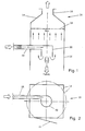
- the separator shown in FIGS. 1 and 2, generally indicated by reference number 10, has a vertically arranged hood 12 which is open at the bottom and has a regular cross section; As can be seen from FIG. 2, this cross section is generally rectangular, in particular square, or circular, as indicated by the dash-dotted lines.
- the door 24 is used for easy inspection and cleaning of the separator 10.
- the hood of the separator 10 is provided with an outlet funnel 14 with an outlet opening 16 which has a smaller cross section than the hood 12.
- a fan (not shown) is connected to the outlet opening 16.
- a transport pipe 22 generally a transport pipe, is fed, which is fed the two-phase mixture to be separated, ie the mixture of tobacco / gas.
- the direction of transport is indicated by the large arrow, while the flows of the two phases of the tobacco / gas mixture in line 12 are indicated by the two different arrows.
- the transport line 22 opens tangentially into the deflection space 20 has a circular cross section and is usually designed as a vertically arranged cylinder which is closed at the top and open at the bottom.
- the tobacco / gas mixture arriving from line 22 lies tangentially against the inner wall of the deflection space 20 and is supplied on a spiral path along the inner wall of the deflection space 20 while simultaneously braking the lower opening of the deflection space 20.
- the tobacco particles fall down, as indicated by the arrows, while the lighter phase, namely gas, is sucked up by the fan and exits from the outlet opening 16 of the hood 12.
- a flow resistance 18 is arranged in the upper area of the hood, i.e. somewhat below the funnel 14, but above the deflection space 20, which consists of a perforated plate with holes evenly distributed over its surface.
- the hood 12 can be open at the bottom, as can be seen from FIG. In this case, the separator 10 can be operated without a discharge element for the separated tobacco particles that is susceptible to malfunction, in particular contamination.
- this discharge element is formed by a cellular wheel sluice 28 which is located in the outlet opening in the funnel-shaped, lower region 26 of the hood 12.
- the embodiment according to FIG. 3 also differs from the embodiment according to FIGS. 1 and 2 by an additionally provided sieve 30; this sieve 30 is in the hood 12 between the Deflection chamber 20 and the flow resistance 18 arranged and prevents the entrainment of tobacco particles in the suction line connected to the outlet 16.
- the horizontal flow cross section of the hood 13 must be chosen so large that the vertical flow rate of the gas phase is always lower than the sinking rate of the tobacco particles to be separated, i.e. the separator 10 must be designed taking into account the highest expected gas flow on the one hand and the lowest expected sink rate of the tobacco particles on the other.
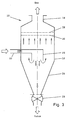
- FIG. 4 shows an embodiment of a separator 10 which can be used when the gas phase consists of steam or contains condensing components.
- the walls of the hood 12 should be provided with a heater in order to prevent condensation and the resulting contamination of the walls.
- the heating in the wall of the hood 12 is indicated by the zigzag line.
- the gas phase consisting of steam or containing condensing components is drawn off to the left as shown in FIG. 4 and fed to an outlet connection 32 which is inclined somewhat downward in relation to the horizontal in the outflow direction, so that the condensate formed there collects at the bottom of the outlet connection 32 and can be discharged via a line 34.
- this embodiment has the structure already described, so that it does not have to be described again.
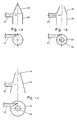
- FIG. 5a shows different embodiments of the deflection space.
- the cylindrical deflection space 20 is provided with a closed, pointed roof 38, so that no tobacco particles or contaminants can be deposited on the deflection space.
- FIGS. 5b and 5c finally show embodiments of deflection spaces 20 which are open at the top.
- FIG. 5b shows an embodiment in which a funnel-shaped area 4 adjoins the cylindrical deflection space 20, which is provided with a cleaning opening at its upper end, so that the interior of the deflection space 20 is freely accessible, in particular for cleaning purposes.
- FIG. 5c shows an embodiment of the deflection space, which has side walls 42 which run obliquely inwards over its entire height and is likewise provided with a cleaning opening 44 at its upper end. The result is a smooth inner wall of the deflection space 42, so that the deposition of tobacco particles or impurities is largely excluded.
- FIGS. 6 and 7 show an embodiment of a separator which differs from the previously discussed embodiments in that two deflection spaces 20 are arranged vertically next to one another in the hood 12. Each deflection space 20 is provided with an associated transport line 22 for supplying the tobacco / gas mixture.
- FIG. 8 finally shows an embodiment of the separator 10 corresponding to FIGS. 1 and 2, but with a deflection space 20 corresponding to FIG. 5b.
- 1,500 kg of tobacco per hour were injected with a gas or steam mass flow of 500 kg / hour. processed.
- the inlet speed of the tobacco / gas mixture was of the order of magnitude of about 20 m / s required for the pneumatic transport.
- the speed of the gas drawn off was between 0.1 and 0.2 m / s, for which purpose a vacuum of 5 mbar was maintained in the upper, funnel-shaped end region of the hood 12.
Abstract
Description
Die Erfindung betrifft eine Abscheider zur Trennung von Tabak-Teilchen aus einem Tabak/Gas-Gemisch der im Oberbegriff des Anspruchs 1 angegebenen Gattung.The invention relates to a separator for separating tobacco particles from a tobacco / gas mixture of the type specified in the preamble of claim 1.
Im Verlaufe der Tabak-Vorbereitung, aber insbesondere bei der Behandlung von expandierten Tabak, dessen Herstellung bspw. aus der älteren Patentanmeldung P 37 10 677.5-23 hervorgeht, müssen die Tabak-Teilchen aus dem vorliegenden Tabak/Gasgemisch abgetrennt werden. Insbesondere bei der Expansion von Tabak wird manchmal auch Dampf eingesetzt, so daß im folgenden der Begriff "Gas" auch dampfförmige Medien umfassen soll.In the course of the tobacco preparation, but especially in the treatment of expanded tobacco, the manufacture of which is evident, for example, from the earlier patent application P 37 10 677.5-23, the tobacco particles must be separated from the present tobacco / gas mixture. In particular, steam is sometimes used in the expansion of tobacco, so that in the following the term "gas" is also intended to include vaporous media.
Die Grundprinzipien der Teilchenabscheidung durch Massenkräfte gehen bspw. aus Ullmanns Enzyklopädie der Technischen Chemie, 4. Auflage, Band 2, Verfahrenstechnik I hervor. Solche "Abscheider" sind auch bereits in der Tabakindustrie eingesetzt worden. So geht aus der DE-OS 36 19 816 eine Vorrichtung zum Expandieren von Tabak hervor, die neben einem Zyklonstaubabscheider einen Abscheider mit einem Maschensieb enthält. Das Maschensieb ermöglicht den Durchlaß des Dampf/Luft-Gemisches zu einem Auslaßrohr, das es wieder dem Kreislauf zuführt, während die Tabak-Teilchen nach unten zu einer Luftschleuse geführt werden.The basic principles of particle separation by mass forces can be found, for example, in Ullmann's Encyclopedia of Technical Chemistry, 4th edition, volume 2, Process engineering I. Such "separators" have also been used in the tobacco industry. DE-OS 36 19 816 shows a device for expanding tobacco which, in addition to a cyclone dust separator, contains a separator with a mesh screen. The mesh screen allows the vapor / air mixture to pass to an outlet tube which it recirculates while the tobacco particles are directed down to an airlock.
Aus der EP-OS 29 588 geht ein Verfahren zur Erwärmung von Tabak, der mit einem Expansionsmittel imprägniert ist, hervor, bei dem das expandierten Tabak enthaltende Gas mittels eines Tangentialseparators von den Tabak-Teilchen getrennt wird.EP-OS 29 588 discloses a process for heating tobacco which is impregnated with an expansion agent, in which the gas containing expanded tobacco is separated from the tobacco particles by means of a tangential separator.
Ein Abscheider der angegebenen Gattung zur Abtrennung von Staubteilchen aus einem Gas geht aus der DE-PS 639 871 hervor. Dabei ist an den Einlaß ein Ringkanal angeschlossen, von dessen Unterseite mehrere, kranzartig angeordnete Kanäle in schraubenförmigen Windungen im gleichen Drehsinn wie die Rohgaszuleitung nach unten führen und in eine unterhalb des Ringkanals liegende Kammer in stetigem Übergang an die Kammerwandung münden; der Krümmungshalbmesser dieser Kanäle ist kleiner als der halbe Durchmesser der Haube.A separator of the type specified for separating dust particles from a gas is apparent from DE-PS 639 871. In this case, an annular channel is connected to the inlet, from the underside of which several, wreath-like channels in helical windings lead in the same direction as the raw gas supply line downwards and open into a chamber below the annular channel in a continuous transition to the chamber wall; the radius of curvature of these channels is smaller than half the diameter of the hood.
Es handelt sich also um eine Ausführungsform eines Fliehkraftabscheiders, bei dem die Gemischströme mit relativ großer Geschwindigkeit transportiert werden müssen, um aufgrund der Bewegungsänderung beim Durchlaufen der gekrümmten Kanäle die gewünschte Abscheidung hervorzurufen.It is therefore an embodiment of a centrifugal separator in which the mixture flows have to be transported at a relatively high speed in order to produce the desired separation due to the change in movement when passing through the curved channels.
Nachteilig ist hierbei der relativ große apparative Aufwand für die erforderliche hohe Transportgeschwindigkeit sowohl im Einlaß als auch in dem Umlenkraum und schließlich in der Haube; außerdem ist für die einwandfreie Funktion dieses Abscheiders unbedingt erforderlich, daß alle mit dem Staub/Gasgemisch in Berührung kommenden Räume, insbesondere die schraubenförmig gekrümmten Kanale, sorgfältig saubergehalten werden, da Ablagerungen an deren Wänden, insbesondere verkrustete Teilchen, sofort zu einer Beeinträchtigung des Abscheidungs-Wirkungsgrades füh ren. Und schließlich muß das untere Ende der Haube, bspw. durch eine Zellradschleuse, geschlossen gehalten werden, um die erforderlichen, hohen Fördergeschwindigkeiten zu gewährleisten. Es gibt jedoch viele Anwendungsfälle, bei denen mit offenem Auslaß gearbeitet werden kann oder muß.The disadvantage here is the relatively large amount of equipment required for the required high transport speed both in the inlet and in the deflection space and finally in the hood; In addition, for the proper functioning of this separator, it is absolutely essential that all rooms that come into contact with the dust / gas mixture, in particular the helically curved channels, are carefully kept clean, since deposits on their walls, in particular encrusted particles, immediately impair the separation Efficiency And finally, the lower end of the hood, for example by a rotary valve, must be kept closed in order to ensure the required high conveying speeds. However, there are many applications in which an open outlet can or must be used.
Der Erfindung liegt deshalb die Aufgabe zugrunde, einen Abscheider der angegebenen Gattung zu schaffen, bei dem die oben erwähnten Nachteile nicht auftreten.The invention is therefore based on the object of providing a separator of the type specified, in which the disadvantages mentioned above do not occur.
Insbesondere soll ein Abscheider vorgeschlagen werden, der auf konstruktiv einfache Weise mit relativ geringen Fördergeschwindigkeiten die einwandfreie Trennung Gas/Tabak-Teilchen ermöglicht.In particular, a separator is to be proposed which enables the gas / tobacco particles to be separated properly in a structurally simple manner with relatively low conveying speeds.
Dies wird erfindungsgemäß durch die im kennzeichnenden Teil des Anspruchs 1 angegebenen Merkmale erreicht.This is achieved according to the invention by the features specified in the characterizing part of claim 1.
Zweckmäßige Ausführungsformen gehen aus den Merkmale der Unteransprüche hervor.Appropriate embodiments emerge from the features of the subclaims.
Die mit der Erfindung erzielten Vorteile beruhen auf der speziellen Ausgestaltung eines Fliehkraftabscheiders, dessen Umlenkraum durch einen einfachen, nach oben geschlossenen und nach unten offenen Zylinder gebildet wird, der sich in einem weiteren, im folgenden als "Haube" bezeichneten Behälter befindet, so daß die nach unten aus dem Umlenkraum austretende Gasphase nach oben über den gesamten, wirksamen Strömungsdurchschnitt der Haube abgezogen wird, während die Tabak-Teilchen aus dem Umlenkraum frei nach unten aus der Haube herausfallen.The advantages achieved with the invention are based on the special design of a centrifugal separator, the deflection space of which is formed by a simple cylinder which is closed at the top and is open at the bottom and which is located in a further container, hereinafter referred to as "hood", so that the the gas phase emerging downward from the deflection space is drawn off upward over the entire effective flow average of the hood, while the tobacco particles fall freely out of the deflection space downward out of the hood.
Der horizontale Strömungsquerschnitt der Haube muß so groß gewählt werden, daß die vertikale Strömungsgeschwindigkeit der Gasphase immer geringer ist als die Sinkgeschwindigkeit der abzuscheidenden Tabak-Teilchen, d.h. das Gesamtsystem muß unter Berücksichtigung des höchsten, zu erwartenden Gasstroms einerseits und der geringsten, zu erwartenden Sinkgeschwindigkeit der Tabak-Teilchen andererseits ausgelegt werden.The horizontal flow cross section of the hood must be chosen so large that the vertical flow rate of the gas phase is always lower than the sinking rate of the tobacco particles to be separated, i.e. the overall system must take into account the highest expected gas flow on the one hand and the lowest expected sinking rate of the On the other hand, tobacco particles can be designed.
Um diese Bedingungen zu gewährleisten, muß das Größenverhältnis der Fläche des Umlenkraums zu der Fläche des Einlasses im Bereich von 5 bis 30 liegen; gleichzeitig muß das Größenverhältnis der Fläche der Haube zu der Fläche des Einlasses größer als 50, insbesondere größer als 100 sein.To ensure these conditions, the size ratio of the area of the deflection space to the area of the inlet must be in the range from 5 to 30; at the same time the size ratio of the area of the hood to the area of the inlet must be greater than 50, in particular greater than 100.
Am Einlaß dieses Abscheiders treten die üblichen, für den pneumatischen Transport des Gemisches Tabak/Gas erforderlichen Geschwindigkeiten im Bereich von etwa 20 m/s auf, während die Gas-Austrittsgeschwindigkeiten am oberen Ende der Haube im Bereich von etwa 0,1 bis 0,2 m/s liegen.At the inlet of this separator, the usual speeds required for the pneumatic transport of the tobacco / gas mixture occur in the range of approximately 20 m / s, while the gas outlet speeds at the upper end of the hood range from approximately 0.1 to 0.2 m / s.
Der erforderliche pneumatische Transport des Gemisches endet praktisch an der Wand des Umlenkraumes, da dort die Tabak-Teilchen aufgrund der Schwerkraft frei nach unten fallen, während das Gas durch eine über dem Umlenkraum befindliche Absaugvorrichtung aus der Haube nach oben abgezogen wird.The required pneumatic transport of the mixture practically ends on the wall of the deflection space, since there the tobacco particles fall freely due to gravity, while the gas is drawn up from the hood by a suction device located above the deflection space.
Wird der Abscheider so betrieben, daß an dem unteren Auslaß der Haube ungefähr Umgebungsdruck herrscht, so kann die Haube nach unten geöffnet sein, d.h. der Abscheider kann ohne störungsanfälliges, insbesondere verschmutzungsanfälliges Austragsorgan betrieben werden.If the separator is operated so that there is approximately ambient pressure at the lower outlet of the hood, the hood can be opened downwards, i.e. the separator can be operated without a discharge element which is susceptible to malfunction, in particular contamination.
Schwankende Durchsatzleistungen der Gas- und/oder der Tabakphase haben im Gegensatz zu den herkömmlichen Abscheidern, nämlich Zyklonen oder Tangential-Separatoren, keinen nennenswerten Einfluß auf den Abscheidegrad, da bei dem hier beschriebenen, offenen Abscheider bei einer Änderung der Durchsatzleistung nur mehr oder weniger Falschluft angesaugt wird, also die vertikale Strömungsgeschwindigkeit der Gasphase näherungsweise konstant bleibt.In contrast to the conventional separators, namely cyclones or tangential separators, fluctuating throughputs of the gas and / or tobacco phases have no significant influence on the degree of separation, since with the open separator described here, when the throughput rate changes, only more or less false air is removed is sucked in, i.e. the vertical flow velocity of the gas phase remains approximately constant.
Damit wird eine Trennung der Tabak-Teilchen aus dem Tabak/Gas-Gemisch auch ohne Einsatz einer Zellenradschleuse möglich, was auf der erläuterten Unempfindlichkeit des Abscheiders gegen Falschluft beruht. Da - im Gegensatz zu Zyklonen oder anderen, herkömmlichen Tangential-Abscheidern - die Gasphase im größten Querschnitt der Haube abgesaugt werden kann, ergibt sich eine Vergleichmäßigung der Strömung und damit eine relativ hohe Unempfindlichkeit des Abscheidegrades von den Betriebsparametern.This makes it possible to separate the tobacco particles from the tobacco / gas mixture even without using a rotary valve, which is based on the explained insensitivity of the separator to false air. Since - in contrast to cyclones or other conventional tangential separators - the gas phase can be extracted in the largest cross section of the hood, the flow is evened out and therefore a relatively high degree of insensitivity to the degree of separation from the operating parameters.
Herrscht jedoch im Gesamtsystem ein innerer Überdruck, so muß die Haube nach unten durch ein Austragsorgan abgeschlossen werden, im allgemeinen eine Zellenradschleuse oder eine Austragsschnecke.However, if there is an internal overpressure in the overall system, the hood must be closed at the bottom by a discharge element, generally a cellular wheel sluice or a discharge screw.
Beim geschlossenen Abscheider verbessert sich der Abscheidegrad mit abnehmender Gasphase, da in diesem Fall die Differenz zwischen der vertikalen Strömungsgeschwindigkeit der Gasphase und der Sinkgeschwindigkeit der Tabak-Teilchen größer wird.When the separator is closed, the degree of separation improves with decreasing gas phase, since in this case the difference between the vertical flow rate of the gas phase and the sinking rate of the tobacco particles increases.
Selbst wenn Tabak/Gas-Gemische, die erhebliche Verschmutzungen verursachen behandelt werden müssen, verschlechtert sich der Abscheidegrad nur unwesentlich, so daß an die entsprechende Tabakvorbereitung keine großen Anforderungen gestellt werden müssen.Even if tobacco / gas mixtures that cause considerable contamination have to be treated, the degree of separation deteriorates only insignificantly, so that no great demands have to be made on the corresponding tobacco preparation.
Auch die nicht zu vermeidenden Verkrustungen an den Innenflächen von Einlaß, Umlenkraum und Haube beeinflussen den Abscheide-Wirkungsgrad nur unwesentlich, so daß die bisher übliche, sehr sorgfältige Reinigung nur in größeren Zeitabständen vorgenommen werden muß.Even the unavoidable incrustations on the inner surfaces of the inlet, deflection chamber and hood only have an insignificant effect on the separation efficiency, so that the previously very careful cleaning only has to be carried out at longer intervals.
Weiterhin können nun auch mehrere Tabak/Gas-Gemische in einem Abscheider einfach getrennt werden, indem die verschiedenen, zu trennenden Zweiphasen-Strömungen zusammengeschaltet werden.Furthermore, several tobacco / gas mixtures can now be easily separated in one separator by interconnecting the different two-phase flows to be separated.
Aufgrund der niedrigen, in dem Abscheider auftretenden Strömungsgeschwindigkeiten ergibt sich nur ein geringer Druckverlust, so daß auch in soweit die Verfahrensführung bei vermindertem Energieaufwand einfach wird.Because of the low flow velocities that occur in the separator, there is only a small pressure loss, so that the process is easy with less energy consumption.
Um eine gleichmäßige Strömungsgeschwindigkeit über den Haubenquerschnitt zu erreichen, wie es für die homogene Trennung der Tabak-Teilchen erforderlich ist, wird im oberen Bereich der Haube ein Strömungswiderstand angeordnet, der in der Regel aus einem Lochblech mit gleichmäßig über die Lochblechfläche verteilten Löchern besteht.In order to achieve a uniform flow velocity across the hood cross-section, as is required for the homogeneous separation of the tobacco particles, a flow resistance is arranged in the upper area of the hood, which usually consists of a perforated plate with holes evenly distributed over the perforated plate surface.
Um das Mitreißen von Tabak-Teilchen in die Absaugleitung für das Gas zu verhindern, kann unterhalb des Strömungswiderstandes ein Sieb oder Filter angeordnet sein; als Alternative hierzu ist es auch möglich, den Strömungswiderstand selbst als Sieb oder Filter auszubilden.In order to prevent tobacco particles from being carried into the suction line for the gas, a sieve or filter can be arranged below the flow resistance; as an alternative to this, it is also possible to design the flow resistance itself as a sieve or filter.
Um die Reinigung des Abscheiders zu vereinfachen, kann in der Haube und/oder dem Umlenkraum eine durch eine Tür verschließbare Öffnung vorgesehen sein, die den Zugang zum Innern der Haube bzw. des Umlenkraumes ermöglicht.In order to simplify the cleaning of the separator, an opening which can be closed by a door and which allows access to the interior of the hood or the deflection space can be provided in the hood and / or the deflection space.
Enthält die Gasphase Dampf oder andere, kondensierende Anteile, so wird nach einer bevorzugten Ausführungsform die Wand der Haube mit einer Heizung versehen, um eine Betauung und daraus resultierende Verschmutzungen der Wände zu verhindern.If the gas phase contains steam or other condensing components, then according to a preferred embodiment the wall of the hood is provided with a heater in order to prevent condensation and the resulting contamination of the walls.
Schließlich ist es noch möglich, mehrere Umlenkräume nebeneinander in einer Haube anzuordnen und dadurch mehrere, zu trennende Tabak/Gas-Gemische zusammenzuschalten, wobei jeweils ein Gas- und ein Tabak-Teilchen-Strom erzeugt werden.Finally, it is also possible to arrange a plurality of deflection spaces next to one another in a hood and thereby interconnect a plurality of tobacco / gas mixtures to be separated, a gas and a tobacco particle stream being generated in each case.
Die Erfindung wird im folgenden anhand von Ausführungsbeispielen unter Bezugnahme auf die beiliegenden, schematischen Zeichnungen näher erläutert. Es zeigen
- Fig. 1 einen vertikalen Schnitt durch eine erste Ausführungsform eines Abscheiders,
- Fig. 2 einen horizontalen Schnitt durch den Abscheider nach Figur 1,
- Fig. 3 einen vertikalen Schnitt durch eine andere Ausführungsform eines Abscheiders,
- Fig. 4 einen vertikalen Schnitt durch eine weitere Ausführungsform eines Abscheiders,
- Fig. 5a einen vertikalen Schnitt bzw. eine Draufsicht einer Modifikation des Umlenkraumes,
- Fig. 5b einen vertikalen Schnitt bzw. eine Draufsicht einer weiteren Modifikation des Umlenkraumes,
- Fig. 5c einen vertikalen Schnitt bzw. eine Draufsicht einer weiteren Modifikation des Umlenkraumes,
- Fig. 6 einen vertikalen Schnitt durch einen Abscheider mit zwei zueinander parallelen Umlenkräumen,
- Fig. 7 einen horizontalen Schnitt durch den Abscheider nach Figur 6, und
- Fig. 8 einen vertikalen Schnitt durch eine Ausführungsform des Abscheiders mit Dimensionsangaben.
- 1 is a vertical section through a first embodiment of a separator,
- 2 shows a horizontal section through the separator according to FIG. 1,
- 3 shows a vertical section through another embodiment of a separator,
- 4 shows a vertical section through a further embodiment of a separator,
- 5a is a vertical section or a top view of a modification of the deflection space,
- 5b shows a vertical section or a top view of a further modification of the deflection space,
- 5c shows a vertical section or a top view of a further modification of the deflection space,
- 6 shows a vertical section through a separator with two mutually parallel deflection spaces,
- 7 shows a horizontal section through the separator according to FIG. 6, and
- Fig. 8 is a vertical section through an embodiment of the separator with dimensions.
Der aus den Figuren 1 und 2 ersichtliche, allgemein durch das Bezugszeichen 10 angedeutete Abscheider weist eine vertikal angeordnete, nach unten offene Haube 12 auf, die einen regelmäßigen Querschnitt hat; wie man aus Figur 2 erkennt, hat dieser Querschnitt im allgemeinen Rechteck-, insbesondere Quadrat-Form oder aber Kreisform, wie durch die strichpunktierten Linien angedeutet ist. Die Tür 24 dient zur leichten Inspektion und Reinigung des Abscheiders 10.The separator shown in FIGS. 1 and 2, generally indicated by
An ihrem oberen Ende ist die Haube des Abscheiders 10 mit einem Auslaßtrichter 14 mit einer Auslaßöffnung 16 versehen, die einen kleineren Querschnitt als die Haube 12 hat. An die Auslaßöffnung 16 ist ein Ventilator (nicht dargestellt) angeschlossen.At its upper end, the hood of the
In der Haube 12 befindet sich ein vertikal angeordneter, nach unten offener, runder Umlenkraum 20, dem über eine Transportleitung 22, im allgemeinen ein Transportrohr, das zu trennende Zweiphasengemisch zugeführt wird, also das Gemisch Tabak/Gas. Die Transportrichtung ist durch den großen Pfeil angegeben, während die Strömungen der beiden Phasen des Gemisches Tabak/Gas in der Leitung 12 durch die beiden unterschiedlichen Pfeile angedeutet sind.In the
Die Transportleitung 22 mündet tangential in den Umlenkraum 20, der einen kreisförmigen Querschnitt hat und in der Regel als vertikal angeordneter, oben geschlossener und unten offener Zylinder ausgebildet ist.The
Das von der Leitung 22 ankommende Gemisch Tabak/Gas legt sich tangential an die Innenwand des Umlenkraumes 20 an und wird auf einer spiralförmigen Bahn längs der Innenwand des Umlenkraumes 20 bei gleichzeitiger Abbremsung der unteren Öffnung des Umlenkraumes 20 zugeführt.The tobacco / gas mixture arriving from
Beim Austritt nach unten aus dem Umlenkraum 20 fallen die Tabak-Teilchen nach unten, wie durch die Pfeile angedeutet ist, während die leichtere Phase, nämlich Gas, mittels des Ventilators nach oben abgesaugt wird und aus der Auslaßöffnung 16 der Haube 12 austritt.As it exits downward from the
Um eine gleichmäßige Strömungsgeschwindigkeit über den Querschnitt der Haube 12 zu erreichen, ist im oberen Bereich der Haube, also etwas unter dem Trichter 14, jedoch über den Umlenkraum 20 ein Strömungwiderstand 18 angeordnet, der aus einem Lochblech mit gleichmäßig über seine Fläche verteilten Löchern besteht.In order to achieve a uniform flow velocity over the cross section of the
Wird das Gemisch Tabak/Gas dem Abscheider 10 mit ausreichendem Druck zugeführt, so kann die Haube 12 unten offen sein, wie es aus Figur 1 ersichtlich ist, d.h. in diesem Fall kann der Abscheider 10 ohne störungsanfälliges,insbesondere verschmutzungsanfälliges Austragsorgan für die abgetrennten Tabak-Teilchen betrieben werden.If the tobacco / gas mixture is fed to the
Herrscht jedoch in dem Abscheider bzw. im Gesamtsystem ein innerer Überdruck bzw. Unterdruck, so muß die Haube 12 nach unten durch ein Austragsorgan abgeschlossen werden. Bei der Ausführungsform nach Figur 3 wird dieses Austragsorgan durch eine Zellenradschleuse 28 gebildet, die sich in der Auslaßöffnung im trichterförmigen, unteren Bereich 26 der Haube 12 befindet.However, if there is an internal overpressure or underpressure in the separator or in the overall system, the
Außerdem unterscheidet sich die Ausführungsform nach Figur 3 noch durch ein zusätzlich vorgesehenes Sieb 30 von der Ausführungsform nach den Figuren 1 und 2; dieses Sieb 30 ist in der Haube 12 zwischen dem Umlenkraum 20 und dem Strömungswiderstand 18 angeordnet und verhindert das Mitreißen von Tabak-Teilchen in die an den Auslaß 16 angeschlossene Absaugleitung.In addition, the embodiment according to FIG. 3 also differs from the embodiment according to FIGS. 1 and 2 by an additionally provided
Der horizontale Strömungsquerschnitt der Haube 13 muß so groß gewählt werden, daß die vertikale Strömungsgeschwindigkeit der Gas-Phase immer geringer ist als die Sinkgeschwindigkeit der abzuscheidenden Tabak-Teilchen, d.h. der Abscheider 10 muß unter Berücksichtigung des höchsten, zu erwartenden Gasstroms einerseits und der geringsten, zu erwartenden Sinkgeschwindigkeit der Tabak-Teilchen andererseits ausgelegt werden.The horizontal flow cross section of the hood 13 must be chosen so large that the vertical flow rate of the gas phase is always lower than the sinking rate of the tobacco particles to be separated, i.e. the
Figur 4 zeigt eine Ausführungsform eines Abscheiders 10, die dann eingesetzt werden kann, wenn die Gasphase aus Dampf besteht oder kondensierende Anteile enthält. In diesem Fall sollten die Wände der Haube 12 mit einer Heizung versehen sein, um eine Betauung und die daraus resultierende Verunreinigung der Wände zu verhindern. Die Heizung in der Wand der Haube 12 ist durch die Zick-Zack-Linie angedeutet.FIG. 4 shows an embodiment of a
Am oberen Ende der Haube 12 wird die aus Dampf bestehende oder kondensierende Anteile enthaltende Gas-Phase gemäß der Darstellung in Figur 4 nach links abgezogen und einem Auslaufstutzen 32 zugeführt, der in bezug auf die Horizontale in Ausströmrichtung etwas nach unten geneigt ist, so daß sich das dort entstehende Kondensat am Boden des Auslaufstutzens 32 sammelt und über eine Leitung 34 abgeführt werden kann.At the upper end of the
Am Ende der Leitung 34 erfolgt eine Trennung dieser Phase in das nach unten ausfließende Kondensat einerseits und das Gas andererseits.At the end of
Im übrigen hat diese Ausführungsform den bereits beschriebenen Aufbau, so daß er nicht nochmals beschrieben werden muß.Otherwise, this embodiment has the structure already described, so that it does not have to be described again.
Die Figuren 5a bis 5c zeigen verschiedene Ausführungsformen des Umlenkraumes. Bei der Ausführungsform nach Figur 5a ist der zylindrische Umlenkraum 20 mit einem geschlossenen, spitzen Dach 38 versehen, so daß sich keine Tabak-Teilchen bzw. Verunreinigungen auf dem Umlenkraum ablagern können.Figures 5a to 5c show different embodiments of the deflection space. In the embodiment according to FIG. 5a, the
Die Figuren 5b und 5c zeigen schließlich Ausführungsformen von Umlenkräumen 20, die nach oben offen sind. Durch entsprechende Anpassung der Abmessungen, Drücke und Strömungsgeschwindigkeiten läßt sich gewährleisten, daß auch in diesem Fall die Gasphase und die Tabak-Teilchen nach unten aus dem Umlenkraum 20 abgezogen werden. Sedimente auf dem Umlenkraum können durch diese Modifikation weitgehend vermieden werden.FIGS. 5b and 5c finally show embodiments of
Figur 5b zeigt eine Ausführungsform, bei der sich an den zylindrischen Umlenkraum 20 nach oben ein trichterförmiger Bereich 4 anschließt, der an seinem oberen Ende mit einer Reinigungsöffnung versehen ist, so daß der Innenraum des Umlenkraumes 20, insbesondere für Reinigungszwecke, frei zugänglich wird.FIG. 5b shows an embodiment in which a funnel-shaped
Figur 5c zeigt eine Ausführungsform des Umlenkraumes, der über seine ganze Höhe schräg nach innen verlaufende Seitenwände 42 hat und ebenfalls an seinem oberen Ende mit einer Reinigungsöffnung 44 versehen ist. Es ergibt sich eine glatte Innenwand des Umlenkraumes 42, so daß die Ablagerung von Tabak-Teilchen bzw. Verunreinigungen weitgehend ausgeschlossen wird.FIG. 5c shows an embodiment of the deflection space, which has
Die Figuren 6 und 7 zeigen eine Ausführungsform eines Abscheiders, die sich von den bisher besprochenen Ausführungsformen dadurch unterscheidet, daß in der Haube 12 zwei Umlenkräume 20 vertikal nebeneinander angeordnet sind. Jeder Umlenkraum 20 ist mit einer zugehörigen Transportleitung 22 für die Zuführung des Gemisches Tabak/Gas versehen.FIGS. 6 and 7 show an embodiment of a separator which differs from the previously discussed embodiments in that two
Auf diese Weise können zwei getrennte Gemischströme gleichzeitig verarbeitet werden, wobei ein Gasstrom und ein Tabakstrom erzeugt werden.In this way, two separate mixture streams can be processed simultaneously, producing a gas stream and a tobacco stream.
Durch die Größe der abführenden Transportsysteme kann es zweckmäßig sein, die Haube 12 nach unten zu verjüngen, wie in Fig. 6 dargestellt.Due to the size of the discharging transport systems, it can be expedient to taper the
Figur 8 zeigt schließlich eine Ausführungsform des Abscheiders 10 entsprechend Figur 1 und 2, jedoch mit einem Umlenkraum 20 entsprechend Figur 5b.FIG. 8 finally shows an embodiment of the
In diese Figur sind die Abmessungen bzw. Betriebsbedingungen eingetragen worden, wie sie bei einer Produktionsanlage realisiert worden sind.In this figure, the dimensions or operating conditions have been entered as they have been implemented in a production plant.
Dabei wurden 1 500 kg Tabak pro Stunde mit einem Gas bzw. Dampfmassenstrom von 500 kg/Std. verarbeitet. Die Einlaßgeschwindigkeit des Gemisches Tabak/Gas lag in der für den pneumatischen Transport erforderlichen Größenordnung von etwa 20 m/s.1,500 kg of tobacco per hour were injected with a gas or steam mass flow of 500 kg / hour. processed. The inlet speed of the tobacco / gas mixture was of the order of magnitude of about 20 m / s required for the pneumatic transport.
Die Geschwindigkeit des nach oben abgezogenen Gases lag zwischen 0,1 und 0,2 m/s, wozu im oberen, trichterförmigen Endbereich der Haube 12 ein Unterdruck von 5 mbar aufrechterhalten wurde.The speed of the gas drawn off was between 0.1 and 0.2 m / s, for which purpose a vacuum of 5 mbar was maintained in the upper, funnel-shaped end region of the
Die Tabak-Teilchen fielen aus dem offenen, unteren, auf Umgebungsdruck pu gehaltenen Ende der Haube 12 heraus.The tobacco particles fell out of the open, lower end of the
Der Einlaß 22 für das Tabak/Gasgemisch hatte eine Fläche mit der Größe A₁ = 0,008 m²; der durch einen Zylinder gebildete Umlenkraum 20 hatte eine Fläche der Große A₂ = 0,1 m²; schließlich hatte die Haube 12 eine Fläche der Größe A₃ = 1,4 m².The
Um die gewünschte Schwerkraft-Abscheidung zu erreichen, kann von diesen Werten abgewichen werden; dabei müssen jedoch bestimmte Grenzwerte für die Flächenverhältnisse eingehalten werden, nämlich
5 = A₂ / A₁ = 30 und
A₃ / A₁ = 50
Besonders gute Ergebnisse werden erreicht, wenn das Verhältnis A₂ / A₁ zwischen 10 und 20 liegt und das Verhältnis A₃ / A₁ größer als 100, jedoch kleiner als 200 ist.To achieve the desired gravity separation, you can deviate from these values; However, certain limit values for the area ratios must be observed, namely
5 = A₂ / A₁ = 30 and
A₃ / A₁ = 50
Particularly good results are achieved if the ratio A₂ / A₁ is between 10 and 20 and the ratio A₃ / A₁ is greater than 100 but less than 200.
Claims (18)
Priority Applications (5)
| Application Number | Priority Date | Filing Date | Title |
|---|---|---|---|
| DK377088A DK172024B1 (en) | 1987-07-29 | 1988-07-07 | Separator for separating small pieces of tobacco from a tobacco/gas mixture |
| CA000572671A CA1300042C (en) | 1987-07-29 | 1988-07-21 | Separator for separating tobacco particles from a tobacco/gas mixture |
| FI883548A FI90005C (en) | 1987-07-29 | 1988-07-28 | FRAMEWORK FOR TOOLS AND TOOLS |
| MYPI88000861A MY103137A (en) | 1987-07-29 | 1988-07-29 | Separator for separating tobacco particles from a tobacco/gas mixture |
| AU20185/88A AU600845B2 (en) | 1987-07-29 | 1988-07-29 | Separator for separating tobacco particles from a tobacco/gas mixture |
Applications Claiming Priority (2)
| Application Number | Priority Date | Filing Date | Title |
|---|---|---|---|
| DE3725148 | 1987-07-29 | ||
| DE3725148 | 1987-07-29 |
Publications (3)
| Publication Number | Publication Date |
|---|---|
| EP0301217A2 true EP0301217A2 (en) | 1989-02-01 |
| EP0301217A3 EP0301217A3 (en) | 1989-12-06 |
| EP0301217B1 EP0301217B1 (en) | 1993-02-03 |
Family
ID=6332642
Family Applications (1)
| Application Number | Title | Priority Date | Filing Date |
|---|---|---|---|
| EP88109550A Expired - Lifetime EP0301217B1 (en) | 1987-07-29 | 1988-06-15 | Device for separating tabacco particles for a gas/tobacco mixture |
Country Status (4)
| Country | Link |
|---|---|
| US (1) | US4938235A (en) |
| EP (1) | EP0301217B1 (en) |
| DE (1) | DE3878072D1 (en) |
| HK (1) | HK25794A (en) |
Cited By (6)
| Publication number | Priority date | Publication date | Assignee | Title |
|---|---|---|---|---|
| EP0774213A1 (en) | 1995-11-20 | 1997-05-21 | British-American Tobacco (Germany) GmbH | Method and device for the processing of tobacco leaves for the manufacturing of tobacco cut filler |
| AT403133B (en) * | 1996-03-14 | 1997-11-25 | Scheuch Alois Gmbh | SAFE |
| US5826590A (en) * | 1996-09-26 | 1998-10-27 | Brown & Williamson Tobacco Corp. | Method and plant for treating tobacco stems for the production of cut tobacco |
| EP2045199A1 (en) * | 2007-10-02 | 2009-04-08 | Klaus Wilhelm | Compressed air supply device for bulk material |
| CN104705778A (en) * | 2015-01-19 | 2015-06-17 | 河南中烟工业有限责任公司 | Tobacco dynamic extraction device |
| CN111358034A (en) * | 2020-03-31 | 2020-07-03 | 佛山市高明曦逻科技有限公司 | Tobacco curing barn recovery device and using method thereof |
Families Citing this family (7)
| Publication number | Priority date | Publication date | Assignee | Title |
|---|---|---|---|---|
| CH683226A5 (en) * | 1991-12-09 | 1994-02-15 | Egri Laszlo | Expanding and drying tobacco. |
| US5582193A (en) * | 1994-08-24 | 1996-12-10 | Philip Morris Incorporated | Method and apparatus for expanding tobacco |
| US6371126B1 (en) * | 2000-03-03 | 2002-04-16 | Brown & Williamson Tobacco Corporation | Tobacco recovery system |
| CA2499853C (en) * | 2004-03-15 | 2012-11-13 | Universal Leaf Tobacco Company, Inc. | Apparatus and method for scanning and sorting tobacco leaves |
| DE102005062090B4 (en) * | 2005-12-22 | 2010-01-14 | Hauni Maschinenbau Ag | Visual device and method for separating heavy and light particles of tobacco material |
| US8281931B2 (en) * | 2009-09-18 | 2012-10-09 | Key Technology, Inc. | Apparatus and method for post-threshing inspection and sorting of tobacco lamina |
| CN106617259A (en) * | 2017-02-22 | 2017-05-10 | 广东中烟工业有限责任公司 | Dust-removal and fire-retardance device of negative-pressure pipeline |
Citations (4)
| Publication number | Priority date | Publication date | Assignee | Title |
|---|---|---|---|---|
| DE3026002A1 (en) * | 1979-07-10 | 1981-02-05 | Rothmans Of Pall Mall | METHOD FOR PROCESSING TOBACCO AND DEVICE FOR CARRYING OUT THIS METHOD |
| DE3416701A1 (en) * | 1983-05-19 | 1984-11-22 | Hauni-Werke Körber & Co KG, 2050 Hamburg | Device for loading tobacco-processing extrusion machines |
| DE3409814A1 (en) * | 1984-03-16 | 1985-09-19 | Waeschle Maschinenfabrik Gmbh, 7980 Ravensburg | COUNTERFLOW SITTER |
| DE3700684A1 (en) * | 1986-01-13 | 1987-07-23 | Sumitomo Chemical Co | FLOCK SEPARATING DEVICE AND METHOD |
Family Cites Families (5)
| Publication number | Priority date | Publication date | Assignee | Title |
|---|---|---|---|---|
| DE639871C (en) * | 1936-12-15 | Heinrich Junkmann Dipl Ing | Centrifugal dust separator | |
| US4366825A (en) * | 1979-11-21 | 1983-01-04 | Philip Morris Incorporated | Expansion of tobacco |
| US4407306A (en) * | 1981-12-17 | 1983-10-04 | American Brands, Inc. | Method for expanding tobacco with steam at high temperature and velocity |
| GB8515217D0 (en) * | 1985-06-15 | 1985-07-17 | British American Tobacco Co | Treatment of tobacco |
| DE3710677A1 (en) * | 1987-03-31 | 1988-10-13 | Bat Cigarettenfab Gmbh | DEVICE FOR EXPANDING CRUSHED TOBACCO MATERIAL |
-
1988
- 1988-06-15 EP EP88109550A patent/EP0301217B1/en not_active Expired - Lifetime
- 1988-06-15 DE DE8888109550T patent/DE3878072D1/en not_active Expired - Fee Related
- 1988-07-29 US US07/226,025 patent/US4938235A/en not_active Expired - Fee Related
-
1994
- 1994-03-24 HK HK257/94A patent/HK25794A/en not_active IP Right Cessation
Patent Citations (4)
| Publication number | Priority date | Publication date | Assignee | Title |
|---|---|---|---|---|
| DE3026002A1 (en) * | 1979-07-10 | 1981-02-05 | Rothmans Of Pall Mall | METHOD FOR PROCESSING TOBACCO AND DEVICE FOR CARRYING OUT THIS METHOD |
| DE3416701A1 (en) * | 1983-05-19 | 1984-11-22 | Hauni-Werke Körber & Co KG, 2050 Hamburg | Device for loading tobacco-processing extrusion machines |
| DE3409814A1 (en) * | 1984-03-16 | 1985-09-19 | Waeschle Maschinenfabrik Gmbh, 7980 Ravensburg | COUNTERFLOW SITTER |
| DE3700684A1 (en) * | 1986-01-13 | 1987-07-23 | Sumitomo Chemical Co | FLOCK SEPARATING DEVICE AND METHOD |
Cited By (6)
| Publication number | Priority date | Publication date | Assignee | Title |
|---|---|---|---|---|
| EP0774213A1 (en) | 1995-11-20 | 1997-05-21 | British-American Tobacco (Germany) GmbH | Method and device for the processing of tobacco leaves for the manufacturing of tobacco cut filler |
| AT403133B (en) * | 1996-03-14 | 1997-11-25 | Scheuch Alois Gmbh | SAFE |
| US5826590A (en) * | 1996-09-26 | 1998-10-27 | Brown & Williamson Tobacco Corp. | Method and plant for treating tobacco stems for the production of cut tobacco |
| EP2045199A1 (en) * | 2007-10-02 | 2009-04-08 | Klaus Wilhelm | Compressed air supply device for bulk material |
| CN104705778A (en) * | 2015-01-19 | 2015-06-17 | 河南中烟工业有限责任公司 | Tobacco dynamic extraction device |
| CN111358034A (en) * | 2020-03-31 | 2020-07-03 | 佛山市高明曦逻科技有限公司 | Tobacco curing barn recovery device and using method thereof |
Also Published As
| Publication number | Publication date |
|---|---|
| EP0301217A3 (en) | 1989-12-06 |
| US4938235A (en) | 1990-07-03 |
| EP0301217B1 (en) | 1993-02-03 |
| DE3878072D1 (en) | 1993-03-18 |
| HK25794A (en) | 1994-03-31 |
Similar Documents
| Publication | Publication Date | Title |
|---|---|---|
| EP0301217B1 (en) | Device for separating tabacco particles for a gas/tobacco mixture | |
| DE2825273A1 (en) | SEPARATOR | |
| EP0182000B1 (en) | Cyclone filter with all metal tandem filter candle | |
| CH636533A5 (en) | FILTER DEVICE FOR FILTERING POLLUTED AIR AND DUST FIBER. | |
| WO2007073783A1 (en) | System for gas cleaning | |
| DE2719544C2 (en) | Device for cleaning a filter bed made of granular material | |
| DE1274560B (en) | Device for dedusting industrial gases | |
| EP2465617A1 (en) | Method and device for separating fine particles from granulate bulk goods in a pipe | |
| DE2251513A1 (en) | PROCEDURE AND DEVICE FOR PREVENTING CLOSURE OF AIR CONVEYOR SYSTEMS | |
| DE936488C (en) | Cyclone dust collector | |
| EP1364696B1 (en) | Apparatus for cleaning a gas stream | |
| EP0392455B1 (en) | Separator | |
| DE2224519B2 (en) | Single or multi-stage washer | |
| DE2934590C2 (en) | Cyclone separator | |
| DE2038871B2 (en) | Filtration device for separating solids from gaseous media | |
| DE3626053A1 (en) | GRAVITY WINIFIFIER FOR SEPARATING SHEET MATERIALS | |
| EP3453444A1 (en) | Device for separation of solids from gases | |
| EP0125620A1 (en) | Air filter system | |
| DE4307407C2 (en) | Device for the production of cigarettes with separation of the tobacco particles | |
| DE2254162B2 (en) | Device for dedusting exhaust gases | |
| DE202011000826U1 (en) | Plant for cleaning industrial waste gases | |
| EP0264669B1 (en) | Apparatus for the receipt of pourable bulk material | |
| DE2163735B2 (en) | DEVICE FOR SEPARATING LIQUID DROPS FROM A FLOWING GASEOUS MEDIUM | |
| DE2904830C2 (en) | Device for separating fine droplets of mist | |
| DE19738912A1 (en) | Separator removing solids from gaseous flow |
Legal Events
| Date | Code | Title | Description |
|---|---|---|---|
| PUAI | Public reference made under article 153(3) epc to a published international application that has entered the european phase |
Free format text: ORIGINAL CODE: 0009012 |
|
| AK | Designated contracting states |
Kind code of ref document: A2 Designated state(s): BE CH DE FR GB IT LI NL |
|
| PUAL | Search report despatched |
Free format text: ORIGINAL CODE: 0009013 |
|
| AK | Designated contracting states |
Kind code of ref document: A3 Designated state(s): BE CH DE FR GB IT LI NL |
|
| 17P | Request for examination filed |
Effective date: 19900309 |
|
| 17Q | First examination report despatched |
Effective date: 19910920 |
|
| GRAA | (expected) grant |
Free format text: ORIGINAL CODE: 0009210 |
|
| AK | Designated contracting states |
Kind code of ref document: B1 Designated state(s): BE CH DE FR GB IT LI NL |
|
| ITF | It: translation for a ep patent filed |
Owner name: BARZANO' E ZANARDO MILANO S.P.A. |
|
| ET | Fr: translation filed | ||
| GBT | Gb: translation of ep patent filed (gb section 77(6)(a)/1977) |
Effective date: 19930215 |
|
| REF | Corresponds to: |
Ref document number: 3878072 Country of ref document: DE Date of ref document: 19930318 |
|
| PLBE | No opposition filed within time limit |
Free format text: ORIGINAL CODE: 0009261 |
|
| STAA | Information on the status of an ep patent application or granted ep patent |
Free format text: STATUS: NO OPPOSITION FILED WITHIN TIME LIMIT |
|
| 26N | No opposition filed | ||
| REG | Reference to a national code |
Ref country code: CH Ref legal event code: PFA Free format text: BRITISH-AMERICAN TOBACCO (GERMANY) GMBH |
|
| NLT1 | Nl: modifications of names registered in virtue of documents presented to the patent office pursuant to art. 16 a, paragraph 1 |
Owner name: BRITISH-AMERICAN TOBACCO (GERMANY) GMBH |
|
| REG | Reference to a national code |
Ref country code: FR Ref legal event code: CD |
|
| PGFP | Annual fee paid to national office [announced via postgrant information from national office to epo] |
Ref country code: GB Payment date: 20000512 Year of fee payment: 13 |
|
| PGFP | Annual fee paid to national office [announced via postgrant information from national office to epo] |
Ref country code: CH Payment date: 20000515 Year of fee payment: 13 |
|
| PGFP | Annual fee paid to national office [announced via postgrant information from national office to epo] |
Ref country code: NL Payment date: 20000524 Year of fee payment: 13 |
|
| PGFP | Annual fee paid to national office [announced via postgrant information from national office to epo] |
Ref country code: FR Payment date: 20000529 Year of fee payment: 13 |
|
| PGFP | Annual fee paid to national office [announced via postgrant information from national office to epo] |
Ref country code: BE Payment date: 20000605 Year of fee payment: 13 |
|
| PG25 | Lapsed in a contracting state [announced via postgrant information from national office to epo] |
Ref country code: GB Free format text: LAPSE BECAUSE OF NON-PAYMENT OF DUE FEES Effective date: 20010615 |
|
| PGFP | Annual fee paid to national office [announced via postgrant information from national office to epo] |
Ref country code: DE Payment date: 20010616 Year of fee payment: 14 |
|
| PG25 | Lapsed in a contracting state [announced via postgrant information from national office to epo] |
Ref country code: LI Free format text: LAPSE BECAUSE OF NON-PAYMENT OF DUE FEES Effective date: 20010630 Ref country code: CH Free format text: LAPSE BECAUSE OF NON-PAYMENT OF DUE FEES Effective date: 20010630 Ref country code: BE Free format text: LAPSE BECAUSE OF NON-PAYMENT OF DUE FEES Effective date: 20010630 |
|
| BERE | Be: lapsed |
Owner name: BRITISH-AMERICAN TOBACCO (GERMANY) G.M.B.H. Effective date: 20010630 |
|
| PG25 | Lapsed in a contracting state [announced via postgrant information from national office to epo] |
Ref country code: NL Free format text: LAPSE BECAUSE OF NON-PAYMENT OF DUE FEES Effective date: 20020101 |
|
| GBPC | Gb: european patent ceased through non-payment of renewal fee |
Effective date: 20010615 |
|
| REG | Reference to a national code |
Ref country code: CH Ref legal event code: PL |
|
| PG25 | Lapsed in a contracting state [announced via postgrant information from national office to epo] |
Ref country code: FR Free format text: LAPSE BECAUSE OF NON-PAYMENT OF DUE FEES Effective date: 20020228 |
|
| NLV4 | Nl: lapsed or anulled due to non-payment of the annual fee |
Effective date: 20020101 |
|
| PG25 | Lapsed in a contracting state [announced via postgrant information from national office to epo] |
Ref country code: DE Free format text: LAPSE BECAUSE OF NON-PAYMENT OF DUE FEES Effective date: 20030101 |
|
| PG25 | Lapsed in a contracting state [announced via postgrant information from national office to epo] |
Ref country code: IT Free format text: LAPSE BECAUSE OF NON-PAYMENT OF DUE FEES;WARNING: LAPSES OF ITALIAN PATENTS WITH EFFECTIVE DATE BEFORE 2007 MAY HAVE OCCURRED AT ANY TIME BEFORE 2007. THE CORRECT EFFECTIVE DATE MAY BE DIFFERENT FROM THE ONE RECORDED. Effective date: 20050615 |