EP0301113A1 - Device for cutting tubular foundation piles under water - Google Patents
Device for cutting tubular foundation piles under water Download PDFInfo
- Publication number
- EP0301113A1 EP0301113A1 EP87110888A EP87110888A EP0301113A1 EP 0301113 A1 EP0301113 A1 EP 0301113A1 EP 87110888 A EP87110888 A EP 87110888A EP 87110888 A EP87110888 A EP 87110888A EP 0301113 A1 EP0301113 A1 EP 0301113A1
- Authority
- EP
- European Patent Office
- Prior art keywords
- pile
- supporting shaft
- wall
- tool
- water
- Prior art date
- Legal status (The legal status is an assumption and is not a legal conclusion. Google has not performed a legal analysis and makes no representation as to the accuracy of the status listed.)
- Granted
Links
Images


Classifications
-
- E—FIXED CONSTRUCTIONS
- E02—HYDRAULIC ENGINEERING; FOUNDATIONS; SOIL SHIFTING
- E02D—FOUNDATIONS; EXCAVATIONS; EMBANKMENTS; UNDERGROUND OR UNDERWATER STRUCTURES
- E02D9/00—Removing sheet piles bulkheads, piles, mould-pipes or other moulds or parts thereof
- E02D9/04—Removing sheet piles bulkheads, piles, mould-pipes or other moulds or parts thereof by cutting-off under water
-
- E—FIXED CONSTRUCTIONS
- E21—EARTH DRILLING; MINING
- E21B—EARTH DRILLING, e.g. DEEP DRILLING; OBTAINING OIL, GAS, WATER, SOLUBLE OR MELTABLE MATERIALS OR A SLURRY OF MINERALS FROM WELLS
- E21B7/00—Special methods or apparatus for drilling
- E21B7/12—Underwater drilling
- E21B7/124—Underwater drilling with underwater tool drive prime mover, e.g. portable drilling rigs for use on underwater floors
Definitions
- the invention relates to a method and a device for separating tubular foundation piles under water, in which the wall of the pile is severed by a separating tool inserted into the interior thereof.
- the object of the invention is now to provide a method and an apparatus for separating tubular foundation piles under water of the type mentioned at the outset, which also permit reliable separation of foundation piles in a simple manner even at great water depth, even at a point still below the seabed are applicable from a work ship.
- the attachment and clamping of the implement on the upper edge of the foundation pile can also be carried out relatively quickly and easily from a work ship, the cutting or firing tool located at the lower end of the elongated supporting shaft inserted into the interior of the pile also allowing the pile to be attached to be separated from a place lying under the sea floor, so that no obstacle from the sea floor remains.
- the invention further relates to a device for separating tubular foundation piles under water of the type mentioned in the introduction, which is provided with the features of claim 8.
- This device can be lowered on the crane rope of a working ship and placed so centered on the upper edge of the tubular foundation pile to be separated that the elongated, protruding supporting shaft protrudes centrally into the foundation pile.
- the clamping devices then fix the implement against the circumferential wall of the pile, so that at the same time a centering and a reliable mounting against vertical and horizontal movements, as well as against any torques acting on the cutting tool when cutting the pile wall is achieved.
- the device When using an electro-hydraulic work unit with hydraulic motors that is lowered under water with the implement for rotating the supporting shaft or the tool carrier, and in each case driven by electric motors, either in a closed circuit with a pressure medium container carried along ter connected or in the open circuit simply sucking ambient water, the device can work with great efficiency even in very large water depths without long pressure medium lines.
- the advantageously tubular supporting shaft or the tool carrier is equipped with cutting edges at the lower end, the sediments deposited in the foundation pile to be separated can be simultaneously loosened and washed away when the supporting shaft is inserted into the interior of the foundation pile, so that even with one initially almost completely with solids filled pile, the cutting or burning tool can be inserted to the depth provided for the desired separating cut.
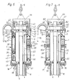
- the implement 1 shown in FIGS. 1 and 2 is lowered on the crane rope 6 of the crane 12 of a work ship 7 next to an oil rig leg 10 under water onto a pile 8, which is attached to a pole bracket attached to the oil rig leg 10 by an annular gap between the pile and the Pile bracket 9 filling concrete layer 11 is permanently connected.
- the working device 1 has an electro-hydraulic drive unit 5, which is supplied with electrical energy via a umbilical 16 hanging from a winch 15 of the working ship 7.
- the umbilical 16 also contains the necessary signal and control lines in a conventional manner.
- the implement 1 also has an elongated, downwardly protruding protective tube 4, through the interior of which a support shaft 3 extends concentrically, which carries a tool holder 2 at its protruding lower end.
- An insertion cone 13 is also arranged around the protective tube 4.
- the length of the implement 1 is dimensioned such that it can be tilted into the position shown in broken lines in FIG. 1 after the conical tool carrier 2 has been inserted into the top opening of the tubular pile 8 by slightly lowering the boom 12 to collide with the pile guide 14 attached to the platform leg. From this position, the implement 1 is then in the in Fig. 2nd shown position lowered, the insertion cone 13 automatically centers the implement 1 on the pile 8 so that the support plate 17 sits on the upper edge of the pile 8.
- clamping jaws 19, which are designed in the embodiment shown as segments of the insertion cone 13, are pressed against the outer peripheral wall of the pile 8, so that the implement is centered on this is clamped and can also absorb any forces resulting from the torque of a cutting tool working on the inner wall of the pile 8.
- the implement 1 is slimmer so that it can sit on the upper edge of the pile 8 deep in the pile holder 9.
- pressure cylinders 20 are provided within the protective tube 4 around the support shaft 3 on the base plate 17, which press the associated clamping jaws 21 through openings 22 in the protective tube 4 against the inner wall of the pile 8.
- the pressure medium supply lines required for actuating the pressure cylinders 20, which are usually connected to a hydraulic accumulator, the return lines to a pressure medium container and the associated changeover valves have not been shown for reasons of clarity.
- the implement 1 is placed on the upper edge of the pile 8, which is guided deep below in the drilling rig leg 10, and has a compensator 23 attached to the top of the drive unit 5, which is attached to two support cables 24 and 25 on the crane 12 of the work ship 7 is suspended.
- the umbilical 16 runs from the winch 15 through the hollow piston rod 26 of the compensator 23 to the drive unit 5.
- the compensator 23 serves to compensate for the relative movements between the implement 1 resting firmly on the pile 8 and the work ship 7 or moving in the sea. the boom of the crane 12.
- the compensator 23 has a cylinder 28 which is divided into an upper chamber 29 and a lower chamber 35 by a piston 27 connected to the piston rod 26.
- the carrying cables 24 and 25 are held taut by the weight of the piston 27 and the piston rod 26.
- the chambers 29 and 35 there is water which, when the piston 27 moves upwards, can escape from the upper chamber 29 through openings 30 in the cylinder cover 31 and, when the piston 27 moves downwards, can flow in reverse through these openings 30 into the upper chamber 29.
- the openings 30 are dimensioned in such a way that they provide little flow resistance to the upward movement corresponding to the relatively slow swell and this can take place practically unhindered.
- the openings 30 act together with one Annular gap 32 between the piston 27 and the wall of the cylinder 28 strongly inhibiting and reduce the falling speed of the implement 1 to such an extent that the remaining kinetic energy is absorbed by the supporting cables 24 and 25 when the mass is intercepted and the implement copes with the interception shock without damage.
- the lower chamber 29 of the cylinder 28 has openings 34 through which water can flow in and out. These openings 34 must be designed to be larger than the openings 30, since the weight of the entire implement acts on the piston 27 via the water cushion in the chamber 29 during the upward movement of the piston 27, but only the weight of the piston 27 and the piston rod 26. This downward movement must not be reduced by flow-related delays, so that the support cables 24 and 25 always remain taut and cannot get caught anywhere.
- the length of the implement 1 is greater which is advantageous for guiding it, since it is thereby always guided in at least two guides 10 a of the oil rig leg 10.
- the carrying cables 24 and 25 are shown rotated by 90 ° in FIG. 4 to show that they run next to the umbilical 16.
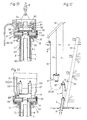
- the implement 1 is placed in a vertical drilling leg 10 on the pile 8 and carries on its top an extension tube 36 to achieve the desired guide length.
- a hydropneumatic compensator 37 of the type described in the German patent application P 35 46 277.9 of the applicant is inserted into the support cables 24 and 25.
- the braking effect can also be better adapted to the respective weight of the implement 1 by adjusting the gas preload pressure.
- these advantages can only be achieved because a tensile force exerted on the implement 1 by the high gas prestress when the compensator is pulled apart by an upward wave movement can be absorbed by the frictional engagement of the clamping jaws 21.
- only the pressure of the pressure medium supplied to the pressure cylinders 20 needs to be increased.
- the drive unit 6 has a drive unit 5 with a closed pressure medium circuit, which has a series of pump units, each with a hydraulic pump 39 flanged to an electric motor 38, each of which has a connecting line 40 with a hydraulic motor 41 and a connecting line 42 with a pressure medium container 43 connected is.
- the support shaft 3, which is driven by the hydraulic motors 41 via a gear 44, is mounted concentrically in the drive unit 5 on the one hand in a bearing 57 of the support plate 17 and on the other hand in a bearing 56 of the cover plate.
- the drive unit 5 has an outer jacket wall 47 connecting the support plate 17 to the cover plate and an inner wall 46 which is concentric with the latter and which is elastically cushioned against the support plate 17 and the cover plate by prestressed spring devices.
- the Pump units are in each case attached to the inner wall 46 distributed over their circumference in the annular space between the latter and the casing wall 47 via supporting projections 48 and elastic support elements 49. Also arranged in the annular space 45 is a water pump 51 which is connected to an electric motor 50 and which draws in ambient water via a suction opening 52 and a filter sieve 52a and feeds it to a purpose explained below by increasing the pressure via a connecting line 53.
- the electric motors 38 and 50 are each supplied with electrical energy from the work ship 7 via electrical lines 54 and 55 contained in the umbilical 16.
- all electric motors 38 and 50 are each connected to a flanged pressure water pump 79, which draws in ambient water via the suction opening 80 and the filter sieve 80a and the pressure water via the connecting lines 81 and 40 to the hydraulic motors 41 for driving the Leading shaft 3 supplies via the gear 44.
- the pressurized water then emerges freely from the outlet port 82 into the environment, so that there is an overall pressure medium circuit that is open to the environment.
- the electric motors 38 and 50 are supplied with electrical energy via the electrical lines 54 and 55 guided in the umbilical 16.
- the support shaft 3 is additionally mounted centrally in a bearing 58 arranged on the protective tube 4 near its lower end and connected at its free end to an exchangeably fastened tool carrier 2 which tapers on the underside and there with cutting edges 59 is provided.
- Clamping jaws 61 are pivotally mounted in lateral openings of the protective tube 4 and can be pressed against the inner wall of the pile 8 by associated hydraulic cylinders 62.
- the tool carrier 2 is driven during the insertion of the protective tube 4 into the pile 8 via the support shaft 3 in the manner of a drill in order to release the settled sediments by means of the cutting edges 59.
- pressurized water can be led down from the water pump 51 to the tool carrier 2 via a connecting line 53, in order to soften the sediments and, after loosening, flush them out upwards out of the pile 8 via the through-channel 60 of the tubular supporting shaft 3.
- the propulsive force required for the penetration is caused by the weight of the implement.
- the clamping jaws 61 Since no large torques occur when the layers of sediment are peeled off, the clamping jaws 61 only need to be slightly pressed against the inner wall of the pile in order to prevent the implement 1 and thus also the umbilical 16 and the supporting cables 6 or 24 and 25 from being twisted, so that they Although the low torque is absorbed by friction, on the other hand the implement 1 can sag automatically under its own weight in accordance with the progress of penetration. If a firmer frictional connection is required, the clamping jaws 61 can of course also be released briefly each time while the supporting shaft 3 is stopped and, after the implement 1 has sagged, can be pressed back onto the inner wall of the pile 8.
- a tool slide 64 is slidably guided in a horizontal guide.
- a cutting tool 65 shown only schematically in FIG. 8 and designed as cutting steel, is attached to the tool slide 64 and produces the desired separating cut in the wall of the pile 8 when the supporting shaft 3 and the tool carrier 2 are rotated.
- the cutting tool 65 can be infinitely adjusted by moving the tool carriage 64 by means of a hydraulic actuating cylinder 66 in order to appropriately adjust the chip thickness in accordance with the processing progress.
- a plurality of underwater cameras 63 are arranged on the inside of the protective tube 4 on the inside over its circumference. Instead, an underwater camera attached to the support shaft 3 or to the tool carrier 2 and rotating with it can also be provided.
- the supply lines of the underwater cameras which are not shown in FIG. 8 for reasons of clarity, can run on the inner wall of the protective tube 4 or via the supporting shaft 3 and a conventional slip ring rotary connection to the drive unit 5.
- a tool slide 67 which is adjustable in a horizontal guide by means of a hydraulic actuating cylinder 78 and which carries an underwater gas flame cutting torch 77, is mounted on the tool carrier 2 provided with conical cutting edges 59.
- the actuating cylinder 78 is fastened to a support block 68, on which a further actuating cylinder 69 for a second tool slide 70 is attached.
- This carries a drilling device 71 with a drilling tool 72 driven by a hydraulic motor 73.
- the drilling device 71 which is driven via pressure medium lines 74 and 75 running in the passage 60 of the supporting shaft 3, is used to create a hole 76 in the wall of the pile 8, that facilitates the approach of the cutting flame to the cut.
- the cutting torch 77 is supplied with fuel gas via a supply line 102 from a gas container carried on the drive unit 5 but not shown.
- cutting and firing tools can also be used, for example for liquid pressure jet cutting with a high-pressure water jet which may be enriched with abrasion particles, or for electric consumable burn-off.
- the pressure medium is supplied from a power station over water via a supply line 83, a distributor 85 and connecting lines 86 and 87 to the hydraulic motors 41 and then flows via the connecting lines 88 and 89 Distributor 85 and a supply line 84 back to a pressure medium tank over water.
- the connecting lines 87 and 88 can be shut off by the valve device 90 as needed to shut down the drive.
- the support plate 17 provided on its underside with pressure cylinders 18 and as segments of the insertion cone 13 is firmly connected via a spacer ring 95 by screws 96 to a support plate 91 and in turn carries the protective tube 4 on its underside.
- the support plate 17 arranged bearings 56 and 57 prevent 3 vertical displacements in cooperation with an annular collar 101 of the supporting shaft.
- the transmission 44 which is only shown schematically, is driven directly by electric motors 97.
- the extension tube 36 enclosing the electric motors 97 or a compensator 23 according to FIG. 4, the outer diameter of which can be adapted to the respective requirements.
- the electric motors 97 are driven via the umbilical 16, the distributor 98 and connecting lines 99 and 100.
- the implement 1 hanging on the suspension cable 6 of the crane 12 of a work ship 7 according to FIG. 10 is lowered with the conical tool carrier 2 into the opening of the pile 8, which is guided in a pile holder 9 at the foot of an oil rig leg 10 is.
- an electro-hydraulic underwater drive unit 5 of the type shown in FIG. 6 hangs on a further suspension cable 94 of the crane 12, the hydraulic pumps 39 of which are connected to the distributor of the implement 1 via connecting lines 92.
- the drive unit 5 is supplied with electrical energy by the work ship 7 via the umbilical 16.
- the short design of the implement 1 also makes the last one relatively short Pile guide 93 above the pile holder 9 still allows insertion of the implement into the pile 8. This mode of operation is advantageous in many cases despite the separate lowering of the drive unit 5 required.
Abstract
Description
Die Erfindung betrifft ein Verfahren und eine Vorrichtung zum Abtrennen rohrförmiger Gründungspfähle unter Wasser, bei welchen die Wandung des Pfahles durch ein in dessen Innenraum eingebrachtes Trennwerkzeug durchtrennt wird.The invention relates to a method and a device for separating tubular foundation piles under water, in which the wall of the pile is severed by a separating tool inserted into the interior thereof.
Zur Ausbeutung von unter dem Meeresboden liegenden Rohstoffvorkommen werden schon seit längerem Bohr- und Förderinseln im offenen Meer aufgestellt, die in der Regel durch in den Meeresboden eingerammte, rohrförmige Gründungspfähle festgelegt werden. Derartige Gründungspfähle werden dabei je nach den Anforderungen entweder durch den Innenraum der rohrförmigen Bohrinselbeine oder durch um deren Fußbereiche angeordnete Pfahlhalterungen eingetrieben und danach meist durch Ausfüllen des Ringspalts zwischen dem aus dem Meeresboden herausragenden Pfahlende und der umgebenden Pfahlhalterung oder Bohrinselbein mit Beton mit der zu verankernden Struktur dauerhaft verbunden. Wenn nun die auf diese Weise ausgebeutete Lagerstätte erschöpft ist, wird die zu deren Ausbeutung benötigte Bohr- oder Förderinsel vielfach nutzlos und zu einem störenden Hindernis für die Schiffahrt. Man hat daher schon einige kleinere, im flachen Wasser stehende und mit nur wenigen Gründungspfählen kleinen Durchmessers und geringer Wandstärke verankerte Strukturen dieser Art dadurch entfernt, daß die zu gehörigen Gründungspfähle durch Unterwasser-Sprengungen dicht über dem Meeresboden zerlegt wurden. Dieses Verfahren ist jedoch für mit zahlreichen großkalibrigen Gründungspfählen hoher Wandstärke in großer Wassertiefe verankerte Strukturen nicht mehr durchführbar, zumal derartige in erheblichem Umkreis alle Lebewesen tötende Unterwasser-Sprengungen in verschiedenen Regionen bereits aus Umweltschutzgründen verboten wurden.For the exploitation of raw material deposits lying under the seabed, drilling and production islands have long been set up in the open sea, which are generally defined by tubular foundation piles rammed into the seabed. Depending on the requirements, such foundation piles are driven either through the interior of the tubular oil rig legs or through pile brackets arranged around their base areas and then mostly by filling the annular gap between the pile end protruding from the sea floor and the surrounding pile bracket or oil rig leg with concrete with the structure to be anchored permanently connected. If the deposit exploited in this way is now exhausted, the drilling or production island required for its exploitation becomes useless in many cases and becomes a disruptive obstacle for shipping. One has therefore already removed some smaller structures of this type standing in shallow water and anchored with only a few foundation piles of small diameter and small wall thickness in that the proper foundation piles were dismantled by underwater blasting just above the sea floor. However, this method can no longer be carried out for structures anchored with numerous large-caliber foundation piles of high wall thickness in great water depths, especially since such underwater explosions in various regions that kill all living beings have already been prohibited in various regions for environmental reasons.
In einem anderen Fall wurde nach Entfernen der Produktionsplattform mittels eines auf der verbleibenden Struktur zentral angebrachten Kranes ein hydraulisch angetriebenes Trennwerkzeug durch die oben offenen Bohrinselbeine in die in deren Fußabschnitten geführten, in den Meeresboden eingetriebenen Gründungspfähle heruntergelassen, wo es sich an der Pfahlwandung selbst führte und in dieser einen zerspanenden Trennschnitt erzeugte. Diese Arbeitsweise erfordert jedoch die Anbringung eines Arbeitsgerüsts auf jedem Bohrinselbein und ist insgesamt sehr zeitraubend und aufwendig. Sie läßt sich überdies nicht für die größeren, in tieferem Wasser gegründeten Bohrinseln anwenden, da diese meist durch eine größere Anzahl von um jedes Bohrinselbein herum gruppierten Gründungspfählen verankert sind, die in an den Bohrinselbeinen angeordneten Pfahlhalterungen geführt und mit diesen nach dem Eintreiben durch Ausfüllen des Ringraumes mit Beton dauerhaft verbunden sind.In another case, after removal of the production platform, a hydraulically driven separating tool was lowered through the open-top drilling platform legs into the foundation piles guided in the foot sections and driven into the sea floor, where it led to the pile wall itself, and by means of a crane mounted centrally on the remaining structure generated a cutting cut in this. However, this method of working requires the installation of a scaffolding on each platform leg and is overall very time-consuming and complex. In addition, it cannot be used for the larger oil rigs, which are founded in deeper water, since these are usually anchored by a larger number of foundation piles grouped around each oil rig leg, which are guided in pile supports arranged on the oil rig legs and then filled with these after driving in by filling in the Annulus are permanently connected with concrete.
Aufgabe der Erfindung ist es nun, ein Verfahren und eine Vorrichtung zum Abtrennen rohrförmiger Gründungspfähle unter Wasser der eingangs genannten Art zu schaffen, die auf einfache Weise auch in großer Wassertiefe ein zuverlässiges Abtrennen von Gründungspfählen auch an einer noch unter dem Meeresboden liegenden Stelle gestatten und auch von einem Arbeitsschiff aus anwendbar sind.The object of the invention is now to provide a method and an apparatus for separating tubular foundation piles under water of the type mentioned at the outset, which also permit reliable separation of foundation piles in a simple manner even at great water depth, even at a point still below the seabed are applicable from a work ship.
Zur Lösung dieser Aufgabe ist das Verfahren zum Abtrennen rohrförmiger Gründungspfähle unter Wasser der eingangs genannten Art mit den Merkmalen des Patentanspruches 1 ausgestattet.To achieve this object, the method for separating tubular foundation piles under water of the type mentioned is equipped with the features of
Das Aufsetzen und Festklemmen des Arbeitsgeräts auf dem Oberrand des Gründungspfahles kann auch von einem Arbeitsschiff aus relativ rasch und einfach durchgeführt werden, wobei das am unteren Ende des in den Innerraum des Pfahles eingeführten, langgestreckten Tragschafts befindliche Schneid- oder Brennwerkzeug erlaubt, den Pfahl auch an einer unter dem Meeresboden liegenden Stelle abzutrennen, so daß von diesem keinerlei vom Meeresboden aufragendes Hindernis zurückbleibt.The attachment and clamping of the implement on the upper edge of the foundation pile can also be carried out relatively quickly and easily from a work ship, the cutting or firing tool located at the lower end of the elongated supporting shaft inserted into the interior of the pile also allowing the pile to be attached to be separated from a place lying under the sea floor, so that no obstacle from the sea floor remains.
Vorteilhafte weitere Ausgestaltungen des Verfahrens sind in den Unteransprüchen 2 bis 7 beschrieben.Advantageous further refinements of the method are described in
Gegenstand der Erfindung ist ferner eine Vorrichtung zum Abtrennen rohrförmiger Gründungspfähle unter Wasser der eingangs bezeichneten Art, die mit den Merkmalen des Patentanspruches 8 versehen ist.The invention further relates to a device for separating tubular foundation piles under water of the type mentioned in the introduction, which is provided with the features of
Diese Vorrichtung kann am Kranseil eines Arbeitsschiffes abgesenkt und auf den Oberrand des abzutrennenden, rohrförmigen Gründungspfahles so zentriert aufgesetzt werden, daß dabei der langgestreckte, abwärts vorstehende Tragschaft zentrisch in den Gründungspfahl hineinragt. Die Klemmvorrichtungen legen das Arbeitsgerät dann gegen die Umfangswand des Pfahles fest, so daß gleichzeitig eine Zentrierung und eine zuverlässige Halterung sowohl gegen vertikale und horizontale Bewegungen, als auch gegen etwaige beim Durchtrennen der Pfahlwand auf das Schneidwerkzeug wirkende Drehmomente erzielt wird.This device can be lowered on the crane rope of a working ship and placed so centered on the upper edge of the tubular foundation pile to be separated that the elongated, protruding supporting shaft protrudes centrally into the foundation pile. The clamping devices then fix the implement against the circumferential wall of the pile, so that at the same time a centering and a reliable mounting against vertical and horizontal movements, as well as against any torques acting on the cutting tool when cutting the pile wall is achieved.
Vorteilhafte weitere Ausgestaltungen dieser Vorrichtung sind in den Unteransprüchen 9 bis 29 beschrieben.Advantageous further developments of this device are described in
Bei Verwendung einer mit dem Arbeitsgerät unter Wasser abgesenkten elektro-hydraulischen Arbeitseinheit mit Hydraulikmotoren zum Verdrehen des Tragschafts oder des Werkzeugträgers sowie jeweils durch Elektromotoren angetriebenen, entweder im geschlossenen Kreislauf mit einem mitgeführten Druckmittelbehäl ter verbundenen oder im offenen Kreislauf einfach Umgebungswasser ansaugenden Pumpen kann die Vorrichtung auch in sehr großen Wassertiefen ohne lange Druckmittelleitungen mit hohem Wirkungsgrad arbeiten. Wenn der vorteilhaft rohrförmig ausgebildete Tragschaft bzw. der Werkzeugträger am unteren Ende mit Schneidkanten ausgerüstet ist, können die im abzutrennenden Gründungspfahl abgesetzten Sinkstoffe beim Einführen des Tragschafts in den Innenraum des Gründungspfahls gleichzeitig gelöst und weggespült werden, so daß auch bei einem zunächst nahezu vollständig mit Feststoffen ausgefüllten Pfahl das Schneid- oder Brennwerkzeug auf die für den gewünschten Trennschnitt vorgesehene Tiefe eingeführt werden kann.When using an electro-hydraulic work unit with hydraulic motors that is lowered under water with the implement for rotating the supporting shaft or the tool carrier, and in each case driven by electric motors, either in a closed circuit with a pressure medium container carried along ter connected or in the open circuit simply sucking ambient water, the device can work with great efficiency even in very large water depths without long pressure medium lines. If the advantageously tubular supporting shaft or the tool carrier is equipped with cutting edges at the lower end, the sediments deposited in the foundation pile to be separated can be simultaneously loosened and washed away when the supporting shaft is inserted into the interior of the foundation pile, so that even with one initially almost completely with solids filled pile, the cutting or burning tool can be inserted to the depth provided for the desired separating cut.
Im folgenden werden bevorzugte Ausführungsformen des erfindungsgemäßen Verfahrens sowie der zugehörigen Vorrichtung unter Bezugnahme auf die beigefügten Zeichnungen näher erläutert. Es zeigen:
- Fig. 1 : eine schematische Ansicht der an einem Tragseil auf einen an einem Bohrinselbein angebrachten Pfahl abgesenkten Vorrichtung,
- Fig. 2 : eine vergrößerte schematische Darstellung der Vorrichtung gemäß Fig. 1 in auf den Pfahl aufgesetzter Stellung,
- Fig. 3 : eine schlankere Ausführungsform der Vorrichtung in auf den tief in einer Pfahlhalterung liegenden Oberrand des Pfahles aufgesetzten Stellung,
- Fig. 4 : die Vorrichtung gemäß Fig. 3 in durch ein Bohrinselbein auf einen darin geführten Pfahl aufgesetzter Stellung,
- Fig. 5 : die Vorrichtung gemäß Fig. 4 in auf einem Gründungspfahl in einem senkrechten Bohrinselbein aufsitzender Stellung,
- Fig. 6 : einen Längsschnitt durch eine mit einer Unterwasser-Antriebseinheit versehene Vorrichtung,
- Fig. 7 : einen Längsschnitt durch eine ähnliche Vorrichtung mit offenem Druckmittelkreislauf,
- Fig. 8 : einen vergrößerten Längsschnitt des unteren Endes des Tragschaftes der Vorrichtung gemäß Fig. 2,
- Fig. 9 : einen vergrößerten Längsschnitt durch den unteren Abschnitt des Tragschaftes einer abgewandelten Vorrichtung,
- Fig. 10 : einen Längsschnitt durch eine Vorrichtung mit Druckmittelzufuhr von einer entfernten Druckmittelquelle,
- Fig. 11 : einen teilweisen Längsschnitt durch eine abgewandelte Vorrichtung und
- Fig. 12 : eine schematische Darstellung einer auf den Rammpfahl abgesenkten Vorrichtung gemäß Fig. 10 mit daneben hängender Antriebseinheit.
- 1 is a schematic view of the device lowered on a supporting rope onto a post attached to an oil rig leg,
- 2: an enlarged schematic representation of the device according to FIG. 1 in the position placed on the pile,
- 3: a slimmer embodiment of the device in the position placed on the upper edge of the pile deep in a pile holder,
- 4: the device according to FIG. 3 in the position placed by an oil rig leg on a pile guided therein,
- 5: the device according to FIG. 4 in a position sitting on a foundation pile in a vertical oil rig leg,
- 6 shows a longitudinal section through a device provided with an underwater drive unit,
- 7: a longitudinal section through a similar device with an open pressure medium circuit,
- 8: an enlarged longitudinal section of the lower end of the supporting shaft of the device according to FIG. 2,
- 9: an enlarged longitudinal section through the lower section of the supporting shaft of a modified device,
- 10: a longitudinal section through a device with pressure medium supply from a remote pressure medium source,
- 11: a partial longitudinal section through a modified device and
- FIG. 12: a schematic representation of a device according to FIG. 10 lowered onto the driven pile with the drive unit hanging next to it.
Das in den Fig. 1 und 2 dargestellte Arbeitsgerät 1 wird am Kranseil 6 des Kranes 12 eines Arbeitsschiffes 7 neben einem Bohrinselbein 10 unter Wasser auf einen Pfahl 8 abgesenkt, der mit einer am Bohrinselbein 10 befestigten Pfahlhalterung durch eine den Ringspalt zwischen dem Pfahl und der Pfahlhalterung 9 ausfüllende Betonschicht 11 dauerhaft verbunden ist. Das Arbeitsgerät 1 besitzt eine elektro-hydraulische Antriebseinheit 5, die über ein von einer Winde 15 des Arbeitsschiffes 7 herabhängendes Umbilical 16 mit elektrischer Energie versorgt wird. Das Umbilical 16 enthält darüber hinaus in herkömmlicher Weise die erforderlichen Signal- und Steuerleitungen. Das Arbeitsgerät 1 weist ferner ein langgestrecktes, abwärts vorstehendes Schutzrohr 4 auf, durch dessen Innenraum sich ein Tragschaft 3 konzentrisch hindurcherstreckt, der an seinem herausragenden unteren Ende einen Werkzeugträger 2 trägt. Um das Schutzrohr 4 herum ist ferner ein Einführkonus 13 angeordnet. Die Länge des Arbeitsgeräts 1 ist so bemessen, daß es nach dem Einführen des konischen Werkzeugträgers 2 in die oberseitige Öffnung des rohrförmigen Pfahles 8 durch leichtes Absenken des Auslegers des Kranes 12 in die in Fig. 1 strichpunktiert dargestellte Stellung gekippt werden kann, ohne dabei mit der darüber am Bohrinselbein befestigten Pfahlführung 14 zu kollidieren. Aus dieser Stellung wird das Arbeitsgerät 1 dann in die in Fig. 2 dargestellte Stellung abgesenkt, wobei der Einführkonus 13 das Arbeitsgerät 1 selbsttätig auf dem Pfahl 8 so zentriert, daß sich die Stützplatte 17 auf dem Oberrand des Pfahles 8 aufsetzt. Durch an der Unterseite der Stützplatte 17 angeordnete, in radialer Richtung einwärts wirkende Anpreßzylinder 18 werden nun Klemmbacken 19, die bei der dargestellten Ausführungsform als Segmente des Einführkonus 13 ausgebildet sind, gegen die äußere Umfangswand des Pfahles 8 angepreßt, so daß das Arbeitsgerät auf diesem zentriert festgeklemmt ist und so auch etwaige aus dem Drehmoment eines an der Innenwand des Pfahles 8 arbeitenden Schneidwerkzeugs herrührende Kräfte aufnehmen kann.The
Bei der in Fig. 3 dargestellten, abgewandelten Ausführungsform ist das Arbeitsgerät 1 schlanker ausgebildet, so daß es sich auf den tief in der Pfahlhalterung 9 liegenden Oberrand des Pfahles 8 aufsetzen kann. Bei dieser Ausführungsform sind innerhalb des Schutzrohres 4 um den Tragschaft 3 herum an der Fußplatte 17 befestigte Anpreßzylinder 20 vorgesehen, welche zugeordnete Klemmbacken 21 durch Öffnungen 22 im Schutzrohr 4 gegen die Innenwand des Pfahles 8 anpressen. In diesen und den folgenden Fig. wurden die zur Betätigung der Anpreßzylinder 20 erforderlichen, üblicherweise mit einem Hydrospeicher verbundenen Druckmittelzuleitungen, die Rückleitungen zu einem Druckmittelbehälter sowie die zugehörigen Umschaltventile aus Übersichtlichkeitsgründen nicht dargestellt.In the modified embodiment shown in Fig. 3, the
Bei der in Fig. 4 gezeigten Ausführungsform ist das Arbeitsgerät 1 auf den Oberrand des tief unten im Bohrinselbein 10 geführten Pfahles 8 aufgesetzt und besitzt einen an der Oberseite der Antriebseinheit 5 angebrachten Kompensator 23, der an zwei Tragseilen 24 und 25 am Kran 12 des Arbeitsschiffes 7 aufgehängt ist. Das Umbilical 16 verläuft von der Winde 15 durch die hohle Kolbenstange 26 des Kompensators 23 zur Antriebseinheit 5. Der Kompensator 23 dient zum Ausgleich der Relativbewegungen zwischen dem fest auf dem Pfahl 8 ruhenden Arbeitsgerät 1 und dem sich im Seegang bewegenden Arbeitsschiff 7 bzw. dem Ausleger des Kranes 12. Der Kompensator 23 besitzt einen Zylinder 28, der durch einen mit der Kolbenstange 26 verbundenen Kolben 27 in eine obere Kammer 29 und eine untere Kammer 35 unterteilt ist. Die Tragseile 24 und 25 werden durch das Gewicht des Kolbens 27 und der Kolbenstange 26 straff gehalten. In den Kammern 29 und 35 befindet sich Wasser, das bei einer Aufwärtsbewegung des Kolbens 27 durch Öffnungen 30 im Zylinderdekkel 31 aus der oberen Kammer 29 entweichen und bei einer Abwärtsbewegung des Kolbens 27 umgekehrt durch diese Öffnungen 30 in die obere Kammer 29 einströmen kann. Die Öffnungen 30 sind so bemessen, daß sie der dem relativ langsamen Seegang entsprechenden Aufwärtsbewegung wenig Durchströmwiderstand entgegensetzen und diese praktisch ungehindert erfolgen kann. Wird dagegen das Arbeitsgerät 1 beim Einführen in das Bohrinselbein 10 versehentlich auf eine Kante aufgesetzt bzw. verkantet eingeführt, so daß es bei weiterem Ablassen der Tragseile 24 und 25 zunächst verharrt und dann plötzlich im freien Fall nachfällt, so wirken die Öffnungen 30 zusammen mit einem Ringspalt 32 zwischen dem Kolben 27 und der Wandung des Zylinders 28 stark hemmend und vermindern die Fallgeschwindigkeit des Arbeitsgeräts 1 soweit, daß die verbleibende Bewegungsenergie beim Abfangen der Masse von den Tragseilen 24 und 25 aufgenommen wird und das Arbeitsgerät den Abfangstoß ohne Schaden verkraftet.In the embodiment shown in FIG. 4, the
Die untere Kammer 29 des Zylinders 28 besitzt Öffnungen 34, durch die Wasser ein- und ausströmen kann. Diese Öffnungen 34 müssen größer ausgelegt sein, als die Öffnungen 30, da zwar bei der Aufwärtsbewegung des Kolbens 27 das Gewicht des ganzen Arbeitsgeräts über das Wasserpolster in der Kammer 29 auf den Kolben 27 wirkt, bei dessen Abwärtsbewegung jedoch nur das Gewicht des Kolbens 27 und der Kolbenstange 26. Diese Abwärtsbewegung darf nicht durch strömungsbedingte Verzögerungen verringert werden, damit die Tragseile 24 und 25 immer straff bleiben und sich nirgends verfangen können.The
Da der Kompensator 23 mit der Antriebseinheit 5 direkt verbunden ist, ergibt sich eine größere Länge des Arbeitsgerätes 1 was zu dessen Führung vorteilhaft ist, da es dadurch stets in mindestens zwei Führungen 10a des Bohrinselbeins 10 geführt wird. Die Tragseile 24 und 25 sind in Fig. 4 um 90° verdreht dargestellt, um zu zeigen, daß sie neben dem Umbilical 16 verlaufen.Since the
Bei der in Fig. 5 dargestellten Anordnung ist das Arbeitsgerät 1 in einem senkrechten Bohrinselbein 10 auf den Pfahl 8 aufgesetzt und trägt an seiner Oberseite ein Verlängerungsrohr 36 zur Erzielung der gewünschten Führungslänge. In die Tragseile 24 und 25 ist ein hydropneumatischer Kompensator 37 der in der deutschen Patentanmeldung P 35 46 277.9 der Anmelderin beschriebenen Art eingefügt. Hierdurch kann die Arbeitsweise des Kompensators 37 durch Unterwasserkameras optisch überwacht werden. Auch läßt sich die Bremswirkung durch Anpassung des Gas-Vorspanndruckes dem jeweiligen Gewicht des Arbeitsgerätes 1 besser anpassen. Diese Vorteile lassen sich jedoch nur erzielen, weil ein beim Auseinanderziehen des Kompensators durch eine aufstrebende Wellenbewegung auf das Arbeitsgerät 1 durch die hohe Gasvorspannung ausgeübte Zugkraft durch den Reibschluß der Klemmbacken 21 aufgenommen werden kann. Hierzu braucht nur der Druck des den Anpreßzylindern 20 zugeführten Druckmittels erhöht zu werden.In the arrangement shown in Fig. 5, the implement 1 is placed in a
Das in Fig. 6 dargestellte Arbeitsgerät besitzt eine Antriebseinheit 5 mit geschlossenem Druckmittelkreislauf, die eine Reihe Pumpeneinheiten mit jeweils einer an einem Elektromotor 38 angeflanschten Hydraulikpumpe 39 aufweist, die jeweils über eine Verbindungsleitung 40 mit einem Hydraulikmotor 41 und über eine Verbindungsleitung 42 mit einem Druckmittelbehälter 43 verbunden ist. Der von den Hydraulikmotoren 41 über ein Getriebe 44 angetriebene Tragschaft 3 ist in der Antriebseinheit 5 einerseits in einem Lager 57 der Stützplatte 17 und andererseits in einem Lager 56 der Deckplatte konzentrisch gelagert. Die Antriebseinheit 5 besitzt eine die Stützplatte 17 mit der Deckplatte verbindende äußere Mantelwand 47 und eine zu dieser konzentrische Innenwand 46, die gegen die Tragplatte 17 und die Deckplatte jeweils durch vorgespannte Federvorrichtungen elastisch abgefedert ist. Die Pumpeneinheiten sind jeweils an der Innerwand 46 über deren Umfang verteilt im Ringraum zwischen dieser und der Mantelwand 47 über Tragvorsprünge 48 und elastische Stützelemente 49 angebracht. Im Ringraum 45 ist ferner eine mit einem Elektromotor 50 verbundene Wasserpumpe 51 angeordnet, die über eine Ansaugöffnung 52 und ein Filtersieb 52a Umgebungswasser ansaugt und dieses unter Druckerhöhung über eine Verbindungsleitung 53 einem weiter unten erläuterten Zweck zuführt. Die Elektromotoren 38 und 50 werden jeweils über im Umbilical 16 enthaltene elektrische Leitungen 54 und 55 vom Arbeitsschiff 7 mit elektrischer Energie versorgt.6 has a
Bei der in Fig. 7 dargestellten, abgewandelten Ausführungsform sind alle Elektromotoren 38 und 50 jeweils mit einer angeflanschten Druckwasserpumpe 79 verbunden, die über die Ansaugöffnung 80 und das Filtersieb 80a Umgebungswasser ansaugt und das Druckwasser über die Verbindungsleitungen 81 und 40 den Hydraulikmotoren 41 zum Antrieb des Tragschaftes 3 über das Getriebe 44 zuführt. Das Druckwasser tritt anschließend aus dem Auslaßstutzen 82 frei in die Umgebung aus, so daß sich insgesamt ein zur Umgebung offener Druckmittelkreislauf ergibt. Auch hier werden die Elektromotoren 38 und 50 über die im Umbilical 16 geführten elektrischen Leitungen 54 und 55 mit elektrischer Energie versorgt.In the modified embodiment shown in FIG. 7, all
Bei der in Fig. 8 dargestellten Ausführungsform ist der Tragschafat 3 zusätzlich in einem am Schutzrohr 4 nahe dessen unterem Ende angeordneten Lager 58 zentrisch gelagert und an seinem freien Ende mit einem daran auswechselbar befestigten Werkzeugträger 2 verbunden, der sich unterseitig kugelig verjüngt und dort mit Schneidkanten 59 versehen ist. In seitlichen Öffnungen des Schutzrohres 4 sind Klemmbacken 61 ausschwenkbar gelagert, die durch zugeordnete Hydraulikzylinder 62 gegen die Innenwand des Pfahles 8 angedrückt werden können.In the embodiment shown in FIG. 8, the
Falls der Innenraum des Pfahles 8 weitgehend durch im Laufe der Zeit abgesetzte und verfestigte Sinkstoffe gefüllt ist, die ein hinreichend weites Einführen des Tragschaftes 3 behindern, wird der Werkzeugträger 2 während des Einführens des Schutzrohres 4 in den Pfahl 8 über den Tragschaft 3 nach Art eines Bohrers angetrieben, um mittels der Schneidkanten 59 die abgesetzten Sinkstoffe zu lösen. Gleichzeitig kann über eine Verbindungsleitung 53 Druckwasser von der Wasserpumpe 51 zum Werkzeugträger 2 hinuntergeführt werden, um die Sinkstoffe aufzuweichen und diese nach dem Lösen über dem Durchgangskanal 60 des rohrförmig ausgebildeten Tragschafts 3 nach oben aus dem Pfahl 8 herauszuspülen. Die für den Eindringfortschritt benötigte Vortriebskraft wird durch das Eigengewicht des Arbeitsgeräts bewirkt. Da beim Abschälen der Sinkstoffschichten keine großen Drehmomente auftreten, brauchen die Klemmbacken 61 zur Verhütung eine Verdrehung des Arbeitsgerätes 1 und damit auch des Umbilicals 16 und der Tragseile 6 bzw. 24 und 25 nur leicht an die Innenwand des Pfahles angedrückt zu werden, so daß sie zwar das geringe Drehmoment durch Reibschluß aufnehmen, andererseits aber das Arbeitsgerät 1 unter seinem Eigengewicht entsprechend dem Eindringfortschritt selbsttätig nachsacken kann. Falls ein festerer Reibschluß erforderlich ist, können die Klemmbacken 61 natürlich auch jeweils kurzzeitig unter Stillsetzung des Tragschaftes 3 gelöst und nach erfolgtem Nachsacken des Arbeitsgeräts 1 wieder an die Innenwand des Pfahles 8 angedrückt werden.If the interior of the
Sobald das Arbeitsgerät 1 auf dem Oberrand des Pfahles 8 fest aufsitzt und durch die von den Anpreßzylindern 20 betätigten Klemmbacken 21 in zentrierter Stellung auf den Pfahl festgelegt ist, wird es im unteren Bereich des in den Pfahl 8 hineinragenden, langgestreckten Schutzrohres 4 durch die Klemmbacken 61 nochmals zentrierend an der Innenwand des Pfahles 8 fest abgestützt, so daß der Tragschaft 3 mit dem Werkzeugträger 2 nicht durch Vibrationen in seitliche Schwingungen versetzt werden kann. Wenn beispielsweise der Tragschaft 3 20 m in den Pfahl 8 hineinragt, könnten derartige Schwingungen bei fehlender seitlicher Abstützung im unteren Bereich des Schutzrohres das Durchtrennen der Pfahlwand beeinträchtigen oder sogar unmöglich machen. Die zur Versorgung der Hydraulikzylinder 62 erforderlichen Druckmittelleitungen 62a sind an der Innenwand des Schutzrohres 4 zur Antriebseinheit 5 geführt.As soon as the implement 1 is firmly seated on the upper edge of the
Auf dem Werkzeugträger 2 ist ein Werkzeugschlitten 64 in einer horizontalen Führung verschiebbar geführt. Auf dem Werkzeugschlitten 64 ist ein in Fig. 8 nur schematisch dargestelltes, als Schneidstahl ausgebildetes Schneidwerkzeug 65 angebracht, das bei der Verdrehung des Tragschafts 3 und des Werkzeugträgers 2 den gewünschten Trennschnitt in der Wandung des Pfahles 8 erzeugt. Das Schneidwerkzeug 65 kann durch Verschieben des Werkzeugschlittens 64 mittels eines hydraulischen Stellzylinders 66 stufenlos verstellt werden, um die Spandicke entsprechend dem Bearbeitungsfortschritt zweckentsprechend einzustellen. Zur Beobachtung des Trennschnittes am gesamten Umfang sind am Unterrand des Schutzrohres 4 innenseitig über dessen Umfang verteilt mehrere Unterwasserkameras 63 angeordnet. Stattdessen kann auch eine am Tragschaft 3 bzw. am Werkzeugträger 2 angebrachte, sich mit diesen mitdrehende Unterwasserkamera vorgesehen sein. Die aus Übersichtlichkeitsgründen in Fig. 8 nicht dargestellten Versorgungsleitungen der Unterwasserkameras können an der Innenwand des Schutzrohres 4 bzw. über den Tragschaft 3 und eine herkömmliche Schleifring-Drehverbindung zur Antriebseinheit 5 verlaufen.On the
Bei der in Fig. 9 dargestellten, abgewandelten Ausführungsform ist auf dem mit konischen Schneidkanten 59 versehenen Werkzeugträger 2 ein mittels eines hydraulischen Stellzylinders 78 in einer horizontalen Führung verstellbarer Werkzeugschlitten 67 angebracht, der einen Unterwasser-Gasflammen-Schneidbrenner 77 trägt. Der Stellzylinder 78 ist an einem Abstützblock 68 befestigt, an welchem ein weiterer Stellzylinder 69 für einen zweiten Werkzeugschlitten 70 angebracht ist. Dieser trägt ein Bohrgerät 71 mit einem über einen Hydraulikmotor 73 angetriebenen Bohrwerkzeug 72. Das über im Durchgangskanal 60 des Tragschafts 3 verlaufende Druckmittelleitungen 74 und 75 angetriebene Bohrgerät 71 dient zur Erzeugung eines Loches 76 in der Wandung des Pfahles 8, das den Ansatz der Schneidflamme zum Trennschnitt erleichtert. Dem Schneidbrenner 77 wird über eine Versorgungsleitung 102 Brenngas aus einem an der Antriebseinheit 5 mitgeführten, jedoch nicht dargestellten Gasbehälter zugeführt.In the modified embodiment shown in FIG. 9, a
Anstelle der in den Figuren 8 und 9 dargestellten Schneid- und Brennwerkzeuge können je nach den Anforderungen des Einzelfalles auch andere Trennwerkzeuge, beispielsweise zum Flüssigkeits-Druckstrahlschneiden mit einem gegebenenfalls mit Abriebteilchen angereicherten Hochdruck-Wasserstrahl, bzw. zum elektrischen Abschmelzbrennen benutzt werden.Instead of the cutting and firing tools shown in FIGS. 8 and 9, depending on the requirements of the individual case, other cutting tools can also be used, for example for liquid pressure jet cutting with a high-pressure water jet which may be enriched with abrasion particles, or for electric consumable burn-off.
Bei der in Fig. 10 dargestellten, abgewandelten Vorrichtung ohne angebaute elektrohydraulische Antriebseinheit wird das Druckmittel von einer Kraftstation über Wasser über eine Versorgungsleitung 83, einen Verteiler 85 und Verbindungsleitungen 86 und 87 den Hydraulikmotoren 41 zugeführt und strömt dann über die Verbindungsleitungen 88 und 89, den Verteiler 85 und eine Versorgungsleitung 84 zu einem Druckmittelbehälter über Wasser zurück. Die Verbindungsleitungen 87 und 88 können dabei durch die Ventilvorrichtung 90 je nach Bedarf zur Stillsetzung des Antriebs abgesperrt werden. Die an ihrer Unterseite mit Anpreßzylindern 18 und als Segmenten des Einführkonus 13 ausgebildeten Klemmbacken 19 versehene Stützplatte 17 ist über einen Abstandsring 95 durch Schrauben 96 mit einer Tragplatte 91 fest verbunden und trägt an ihrer Unterseite wiederum das Schutzrohr 4. Die in der Tragplatte 91 bzw. der Stützplatte 17 angeordneten Lager 56 bzw. 57 verhindern im Zusammenwirken mit einem Ringbund 101 des Tragschaftes 3 vertikale Verschiebungen desselben. Diese zum Einsatz in mittleren Wassertiefen wirtschaftlich einsetzbare Ausführungsform führt zu einer leichteren und kürzeren Ausgestaltung des Arbeitsgerätes 1, was dessen Handhabung erleichtert.In the modified device shown in FIG. 10 without an attached electrohydraulic drive unit, the pressure medium is supplied from a power station over water via a supply line 83, a
Bei der in Fig. 11 dargestellten Ausführungsform wird das nur schematisch dargestellte Getriebe 44 direkt durch Elektromotoren 97 angetrieben. Zur Vergrößerung der Führungslänge ist dabei ein die Elektromotoren 97 umschließendes Verlängerungsrohr 36 bzw. ein Kompensator 23 gemäß Fig. 4 vorgesehen, wobei deren Außendurchmesser den jeweiligen Erfordernissen angepaßt werden kann. Die Elektromotoren 97 werden über das Umbilical 16, den Verteiler 98 und Verbindungsleitungen 99 und 100 angetrieben.In the embodiment shown in FIG. 11, the
Bei der in Fig. 12 dargestellten Anordnung wird das am Tragseil 6 des Kranes 12 eines Arbeitsschiffes 7 hängende Arbeitsgerät 1 gemäß Fig. 10 mit dem konischen Werkzeugträger 2 in die Öffnung des Pfahles 8 abgesenkt, der in einer Pfahlhalterung 9 am Fuß eines Bohrinselbeines 10 geführt ist. Neben dem Arbeitsgerät 1 hängt an einem weiteren Tragseil 94 des Kranes 12 eine elektrohydrdaulische Unterwasser-Antriebseinheit 5, der in Fig. 6 dargestellten Bauart, deren Hydraulikpumpen 39 über Verbindungsgleitungen 92 mit dem Verteiler des Arbeitsgeräts 1 verbunden sind. Die Antriebseinheit 5 wird über das Umbilical 16 vom Arbeitsschiff 7 mit elektrischer Energie versorgt. Auf diese Weise werden einerseits die bei langen, bis über Wasser reichenden Druckmittelschläuchen 83 und 84 wegen des erheblichen Strömungswiderstandes und der Viskositätserhöhung durch Abkühlung des Druckmittels im Meerwasser eintretenden Wirkungsverluste vermieden und andererseits wird durch die kurze Bauweise des Arbeitsgeräts 1 auch bei relativ kleinem Abstand der letzten Pfahlführung 93 über der Pfahlhalterung 9 noch ein Einführen des Arbeitsgeräts in den Pfahl 8 ermöglicht. Diese Arbeitsweise ist trotz der erforderlichen separaten Absenkung der Antriebseinheit 5 in vielen Fällen vorteilhaft.In the arrangement shown in FIG. 12, the implement 1 hanging on the
Die vorstehend anhand bevorzugter Ausführungsformen erläuterten Vorrichtungen und Verfahren können vom Fachmann je nach den Anforderungen des Einzelfalles in verschiedener Weise zweckentsprechend abgewandelt werden, sofern das Arbeitsgerät dabei unter Einführen des Tragschafts 3 in den Pfahl 8 auf dessen Oberrand festgesetzt und das Durchtrennen der Pfahlwand durch Verdrehen eines mit dem Tragschaft 3 verbundenen Trennwerkzeugs vorgenommen wird.The devices and methods explained above on the basis of preferred embodiments can be modified appropriately by the person skilled in the art in various ways depending on the requirements of the individual case, provided that the implement is fixed while inserting the supporting
Claims (30)
Priority Applications (5)
| Application Number | Priority Date | Filing Date | Title |
|---|---|---|---|
| DE8787110888T DE3778542D1 (en) | 1987-07-28 | 1987-07-28 | DEVICE FOR SEPARATING TUBULAR FOUNDATION PILES UNDER WATER. |
| EP87110888A EP0301113B1 (en) | 1987-07-28 | 1987-07-28 | Device for cutting tubular foundation piles under water |
| NO873377A NO170894C (en) | 1987-07-28 | 1987-08-12 | EQUIPMENT FOR AA SEPARATE PIPE-FOUNDED FOUNDATION PILLOWS UNDERWATER |
| JP62254523A JPH0678620B2 (en) | 1987-07-28 | 1987-10-07 | Method and device for cutting tubular foundation piles in water |
| US07/133,903 US4856938A (en) | 1987-07-28 | 1987-12-15 | Method of and arrangement for separating tubular foundation piles under water |
Applications Claiming Priority (1)
| Application Number | Priority Date | Filing Date | Title |
|---|---|---|---|
| EP87110888A EP0301113B1 (en) | 1987-07-28 | 1987-07-28 | Device for cutting tubular foundation piles under water |
Publications (2)
| Publication Number | Publication Date |
|---|---|
| EP0301113A1 true EP0301113A1 (en) | 1989-02-01 |
| EP0301113B1 EP0301113B1 (en) | 1992-04-22 |
Family
ID=8197158
Family Applications (1)
| Application Number | Title | Priority Date | Filing Date |
|---|---|---|---|
| EP87110888A Expired - Lifetime EP0301113B1 (en) | 1987-07-28 | 1987-07-28 | Device for cutting tubular foundation piles under water |
Country Status (5)
| Country | Link |
|---|---|
| US (1) | US4856938A (en) |
| EP (1) | EP0301113B1 (en) |
| JP (1) | JPH0678620B2 (en) |
| DE (1) | DE3778542D1 (en) |
| NO (1) | NO170894C (en) |
Cited By (1)
| Publication number | Priority date | Publication date | Assignee | Title |
|---|---|---|---|---|
| CN110374020A (en) * | 2019-06-20 | 2019-10-25 | 安徽建开建设工程有限公司 | Welding excision construction method and its appurtenance in reinforced concrete pile water |
Families Citing this family (26)
| Publication number | Priority date | Publication date | Assignee | Title |
|---|---|---|---|---|
| GB9604917D0 (en) * | 1996-03-08 | 1996-05-08 | Red Baron Oil Tools Rental | Removal of wellhead assemblies |
| DE19620756A1 (en) * | 1996-05-23 | 1997-11-27 | Wirth Co Kg Masch Bohr | Method and device for cutting pipes or pillars anchored in the ground |
| US6102884A (en) | 1997-02-07 | 2000-08-15 | Squitieri; Rafael | Squitieri hemodialysis and vascular access systems |
| US6629565B2 (en) | 2000-07-24 | 2003-10-07 | Smith International, Inc. | Abandonment and retrieval apparatus and method |
| GB2373266B (en) * | 2001-03-13 | 2004-08-18 | Sondex Ltd | Apparatus for anchoring a tool within a tubular |
| US7762977B2 (en) | 2003-10-08 | 2010-07-27 | Hemosphere, Inc. | Device and method for vascular access |
| US20050137614A1 (en) * | 2003-10-08 | 2005-06-23 | Porter Christopher H. | System and method for connecting implanted conduits |
| GB2438349B (en) * | 2005-03-29 | 2009-12-16 | Norse Cutting & Abandonment As | A method and a device for attaching a subsea cutting apparatus |
| US7258597B2 (en) * | 2005-11-09 | 2007-08-21 | Oceaneering International, Inc. | Subsea abrasive jet cutting system and method of use |
| US20070296229A1 (en) * | 2006-06-23 | 2007-12-27 | The Stanley Works | Grappling system |
| US20080028619A1 (en) * | 2006-06-23 | 2008-02-07 | The Stanley Works | Heavy duty material processing shears |
| GB2448358B (en) * | 2007-04-12 | 2009-07-08 | Tidal Generation Ltd | Installation of underwater ground anchorages |
| US20110295181A1 (en) | 2008-03-05 | 2011-12-01 | Hemosphere, Inc. | Implantable and removable customizable body conduit |
| JP5492792B2 (en) | 2008-03-05 | 2014-05-14 | ヘモスフィア,インコーポレイテッド | Vascular access system |
| NL2003656C2 (en) * | 2009-10-16 | 2011-04-19 | Ihc Holland Ie Bv | COMPOSITION OF TELESCOPIC PIPES. |
| EP2395156A1 (en) * | 2010-06-08 | 2011-12-14 | IHC Holland IE B.V. | Method of and system for installing foundation elements in an underwater ground formation |
| DE102011052399B4 (en) | 2011-08-04 | 2014-11-13 | Aker Wirth Gmbh | Method and device for separating pipes |
| AU2012304589B2 (en) | 2011-09-06 | 2016-04-28 | Merit Medical Systems, Inc. | Vascular access system with connector |
| NL2008279C2 (en) * | 2012-02-13 | 2013-08-14 | Ihc Holland Ie Bv | A template for and method of installing a plurality of foundation elements in an underwater ground formation. |
| EP2703564B1 (en) * | 2012-08-30 | 2016-04-27 | BAUER Maschinen GmbH | Guide frame for guiding a milling device |
| WO2015094514A1 (en) | 2013-12-20 | 2015-06-25 | Cryolife, Inc. | Vascular access system with reinforcement member |
| US9464399B2 (en) * | 2014-01-28 | 2016-10-11 | Ats Smart Solutions, Llc | Pile cutter |
| US11383072B2 (en) | 2017-01-12 | 2022-07-12 | Merit Medical Systems, Inc. | Methods and systems for selection and use of connectors between conduits |
| EP3573682A4 (en) | 2017-01-25 | 2020-11-04 | Merit Medical Systems, Inc. | Methods and systems for facilitating laminar flow between conduits |
| EP3600150B1 (en) | 2017-03-24 | 2023-05-17 | Merit Medical Systems, Inc. | Subcutaneous vascular assemblies for improving blood flow |
| CN106836223B (en) * | 2017-04-11 | 2022-06-21 | 国强建设集团有限公司 | Pile pulling method |
Citations (3)
| Publication number | Priority date | Publication date | Assignee | Title |
|---|---|---|---|---|
| DE342498C (en) * | ||||
| US3338305A (en) * | 1965-02-05 | 1967-08-29 | Halliburton Co | Method and apparatus for cutting casing in underwater installations |
| JPS56159426A (en) * | 1980-05-14 | 1981-12-08 | Shoei:Kk | Steel pipe cutter |
Family Cites Families (5)
| Publication number | Priority date | Publication date | Assignee | Title |
|---|---|---|---|---|
| US2622679A (en) * | 1948-10-08 | 1952-12-23 | Russell A Ransom | Inside pipe cutter |
| US3396795A (en) * | 1966-09-09 | 1968-08-13 | Dresser Ind | Tubing cutter |
| US4339008A (en) * | 1980-06-09 | 1982-07-13 | D. B. D. Drilling, Inc. | Well notching tool |
| JPS6043493A (en) * | 1983-08-19 | 1985-03-08 | Chiyoda Kagaku Kenkyusho:Kk | Discoloration inhibitor for copper |
| US4768899A (en) * | 1987-04-20 | 1988-09-06 | Dysarz Edward D | Device and method to cut piles |
-
1987
- 1987-07-28 DE DE8787110888T patent/DE3778542D1/en not_active Expired - Fee Related
- 1987-07-28 EP EP87110888A patent/EP0301113B1/en not_active Expired - Lifetime
- 1987-08-12 NO NO873377A patent/NO170894C/en not_active IP Right Cessation
- 1987-10-07 JP JP62254523A patent/JPH0678620B2/en not_active Expired - Lifetime
- 1987-12-15 US US07/133,903 patent/US4856938A/en not_active Expired - Fee Related
Patent Citations (3)
| Publication number | Priority date | Publication date | Assignee | Title |
|---|---|---|---|---|
| DE342498C (en) * | ||||
| US3338305A (en) * | 1965-02-05 | 1967-08-29 | Halliburton Co | Method and apparatus for cutting casing in underwater installations |
| JPS56159426A (en) * | 1980-05-14 | 1981-12-08 | Shoei:Kk | Steel pipe cutter |
Non-Patent Citations (4)
| Title |
|---|
| BAUMASCHINE & BAUTECHNIK, BMT, Band 30, Nr. 10, Oktober 1983, Seiten 476-483, Wiesbaden, DE; H. KÜHN: "Entwicklungen in der Unterwasser-Rammtechnik" * |
| PATENT ABSTRACTS OF JAPAN, Band 10, Nr. 261 (M-514)[2317], 5. September 1986; & JP-A-61 87 020 (NIPPON KOKAN K.K.) 02-05-1986 * |
| PATENT ABSTRACTS OF JAPAN, Band 10, Nr. 368 (M-543)[2425], 9. Dezember 1986; & JP-A-61 162 637 (HAZAMA GUMI LTD) 23-07-1986 * |
| PATENT ABSTRACTS OF JAPAN, Band 11, Nr. 74 (M-568)[2521], 6. März 1987; & JP-A-61 229 022 (NIPPON STEEL CORP.) 13-10-1986 * |
Cited By (1)
| Publication number | Priority date | Publication date | Assignee | Title |
|---|---|---|---|---|
| CN110374020A (en) * | 2019-06-20 | 2019-10-25 | 安徽建开建设工程有限公司 | Welding excision construction method and its appurtenance in reinforced concrete pile water |
Also Published As
| Publication number | Publication date |
|---|---|
| JPH01102127A (en) | 1989-04-19 |
| NO873377D0 (en) | 1987-08-12 |
| JPH0678620B2 (en) | 1994-10-05 |
| NO873377L (en) | 1989-01-30 |
| NO170894B (en) | 1992-09-14 |
| DE3778542D1 (en) | 1992-05-27 |
| NO170894C (en) | 1992-12-23 |
| EP0301113B1 (en) | 1992-04-22 |
| US4856938A (en) | 1989-08-15 |
Similar Documents
| Publication | Publication Date | Title |
|---|---|---|
| EP0301113B1 (en) | Device for cutting tubular foundation piles under water | |
| EP2322724B1 (en) | Submarine drilling assembly and method for inserting a tubular foundation element into the sea floor | |
| EP0301114B1 (en) | Process for driving pile sections under water | |
| EP0900319B1 (en) | Process and device for separation of pipes or columns fixed in the ground | |
| DE1298472B (en) | Device for pulling and releasing the drill string in drilling rigs or drilling rigs | |
| EP0301116B1 (en) | Submergible electrohydraulic drive unit for hammering and servicing devices in under water operation | |
| DE3047375A1 (en) | "SUBMERSIBLE RAMM DEVICE" | |
| DE1483790A1 (en) | Device for connecting a pipeline to an underwater system | |
| DE2644725A1 (en) | DRILL RIG | |
| DE2006572A1 (en) | Driving method, device for driving an anchor, a pile or the like into the earth and anchor and pile equipment | |
| DE2342566C3 (en) | Process for removing a settled, particulate solid mass | |
| EP3330441B1 (en) | Underwater excavation device and method for excavation | |
| EP0928876A1 (en) | Device for drilling a bore hole in the ground | |
| EP0263967B1 (en) | Submersible pile hammer | |
| DE2912781A1 (en) | DEVICE FOR SUPPORTING TUBES LAYED ON THE SEA BOTTOM IN THE AREA OF SEA BOTTOM RECESSES AND METHOD FOR ATTACHING THIS DEVICE | |
| DE1925912B2 (en) | Apparatus for pulling down an underwater standpipe from a floating platform to an underwater wellhead | |
| EP2093373B1 (en) | Drilling device, in particular for producing blast holes in the bed of a body of water and method for inserting an explosive charge into the bed of a body of water | |
| EP0819819A1 (en) | Milling head,drilling device and method for underwater drilling | |
| EP0312619A1 (en) | Cutting device to cut tubular construction elements | |
| DE2537918A1 (en) | Ice deflector unit for columns in cold sea areas - has vertically oscillating ice-breaking body encircling column at sea level | |
| DE102012218285A1 (en) | Device and method for creating a foundation and foundation | |
| DE3525725C2 (en) | ||
| DE2947211A1 (en) | GUIDE DEVICE FOR A DIVING BELL | |
| DE1433198C (en) | Apparatus for marking and retrieving a subsea wellhead assembly and for reconnecting therewith | |
| EP3029263B1 (en) | Horizontal ground drilling device |
Legal Events
| Date | Code | Title | Description |
|---|---|---|---|
| PUAI | Public reference made under article 153(3) epc to a published international application that has entered the european phase |
Free format text: ORIGINAL CODE: 0009012 |
|
| 17P | Request for examination filed |
Effective date: 19880831 |
|
| AK | Designated contracting states |
Kind code of ref document: A1 Designated state(s): DE FR GB IT NL SE |
|
| 17Q | First examination report despatched |
Effective date: 19900222 |
|
| RAP1 | Party data changed (applicant data changed or rights of an application transferred) |
Owner name: MENCK GMBH |
|
| GRAA | (expected) grant |
Free format text: ORIGINAL CODE: 0009210 |
|
| AK | Designated contracting states |
Kind code of ref document: B1 Designated state(s): DE FR GB IT NL SE |
|
| PG25 | Lapsed in a contracting state [announced via postgrant information from national office to epo] |
Ref country code: IT Free format text: LAPSE BECAUSE OF FAILURE TO SUBMIT A TRANSLATION OF THE DESCRIPTION OR TO PAY THE FEE WITHIN THE PRE;WARNING: LAPSES OF ITALIAN PATENTS WITH EFFECTIVE DATE BEFORE 2007 MAY HAVE OCCURRED AT ANY TIME BEFORE 2007. THE CORRECT EFFECTIVE DATE MAY BE DIFFERENT FROM THE ONE RECORDED.SCRIBED TIME-LIMIT Effective date: 19920422 Ref country code: FR Effective date: 19920422 Ref country code: SE Effective date: 19920422 |
|
| REF | Corresponds to: |
Ref document number: 3778542 Country of ref document: DE Date of ref document: 19920527 |
|
| GBT | Gb: translation of ep patent filed (gb section 77(6)(a)/1977) | ||
| EN | Fr: translation not filed | ||
| PLBE | No opposition filed within time limit |
Free format text: ORIGINAL CODE: 0009261 |
|
| STAA | Information on the status of an ep patent application or granted ep patent |
Free format text: STATUS: NO OPPOSITION FILED WITHIN TIME LIMIT |
|
| 26N | No opposition filed | ||
| NLS | Nl: assignments of ep-patents |
Owner name: MENCK GMBH |
|
| NLT1 | Nl: modifications of names registered in virtue of documents presented to the patent office pursuant to art. 16 a, paragraph 1 |
Owner name: BOMAG-BETEILIGUNGS-GMBH |
|
| REG | Reference to a national code |
Ref country code: GB Ref legal event code: 732E |
|
| PGFP | Annual fee paid to national office [announced via postgrant information from national office to epo] |
Ref country code: NL Payment date: 20000703 Year of fee payment: 14 Ref country code: GB Payment date: 20000703 Year of fee payment: 14 Ref country code: DE Payment date: 20000703 Year of fee payment: 14 |
|
| PG25 | Lapsed in a contracting state [announced via postgrant information from national office to epo] |
Ref country code: GB Free format text: LAPSE BECAUSE OF NON-PAYMENT OF DUE FEES Effective date: 20010728 |
|
| PG25 | Lapsed in a contracting state [announced via postgrant information from national office to epo] |
Ref country code: NL Free format text: LAPSE BECAUSE OF NON-PAYMENT OF DUE FEES Effective date: 20020201 |
|
| GBPC | Gb: european patent ceased through non-payment of renewal fee |
Effective date: 20010728 |
|
| NLV4 | Nl: lapsed or anulled due to non-payment of the annual fee |
Effective date: 20020201 |
|
| PG25 | Lapsed in a contracting state [announced via postgrant information from national office to epo] |
Ref country code: DE Free format text: LAPSE BECAUSE OF NON-PAYMENT OF DUE FEES Effective date: 20020501 |