EP0300939A2 - Device für unfolding and hiding a bed or the like in a false ceiling - Google Patents
Device für unfolding and hiding a bed or the like in a false ceiling Download PDFInfo
- Publication number
- EP0300939A2 EP0300939A2 EP88450028A EP88450028A EP0300939A2 EP 0300939 A2 EP0300939 A2 EP 0300939A2 EP 88450028 A EP88450028 A EP 88450028A EP 88450028 A EP88450028 A EP 88450028A EP 0300939 A2 EP0300939 A2 EP 0300939A2
- Authority
- EP
- European Patent Office
- Prior art keywords
- frame
- panel
- false ceiling
- articulated
- axis
- Prior art date
- Legal status (The legal status is an assumption and is not a legal conclusion. Google has not performed a legal analysis and makes no representation as to the accuracy of the status listed.)
- Withdrawn
Links
Images


Classifications
-
- A—HUMAN NECESSITIES
- A47—FURNITURE; DOMESTIC ARTICLES OR APPLIANCES; COFFEE MILLS; SPICE MILLS; SUCTION CLEANERS IN GENERAL
- A47C—CHAIRS; SOFAS; BEDS
- A47C19/00—Bedsteads
- A47C19/20—Multi-stage bedsteads; e.g. bunk beds; Bedsteads stackable to multi-stage bedsteads
-
- A—HUMAN NECESSITIES
- A47—FURNITURE; DOMESTIC ARTICLES OR APPLIANCES; COFFEE MILLS; SPICE MILLS; SUCTION CLEANERS IN GENERAL
- A47C—CHAIRS; SOFAS; BEDS
- A47C17/00—Sofas; Couches; Beds
- A47C17/84—Suspended beds, e.g. suspended from ceiling
Definitions
- the present invention relates to a device for deployment and retraction in a false ceiling structure of bedding, a sofa or the like.
- the invention relates to a deployment and retraction mechanism intended to be integrated into a suspended storage system of the type described in document EP-A-0182 731.
- This document relates to a hanging storage device with juxtaposed tilting individual boxes characterized in that it consists of a plurality of storage boxes each arranged on the upper face of a rectangular or square plane panel, articulated around an axis parallel to one of the longitudinal sides and in the vicinity of the latter, on two parts mounted fixed at the two lateral ends of the panel, means being provided for locking the panels in a horizontal position and limiting their opening downwards substantially up to vertically, the panels being aligned side by side in one or two directions being parallel to each other and at a very short distance without any fixed structural element interposed between them in the direction of alignment orthogonal to the tilt axes.
- Such a device constitutes a multiple storage structure that can be composed at will since it can extend in two orthogonal directions to form, by virtue of the single underside of the panels juxtaposed in checkerboard form, a practically continuous surface, in the raised position of the storage boxes, without protrusion or recess, constituting in itself a false ceiling that is both aesthetic and functional.
- the object of the invention is to integrate into such a structure a mechanism for deploying bedding or the like allowing the entire retraction of the latter inside said false ceiling.
- the invention relates to a device for deploying and retracting false ceilings of bedding or the like, intended to be integrated into a suspended storage system comprising panels in particular rectangular, planes, juxtaposed, forming false - suspended ceiling and mounted between two stable positions, one, horizontal, closing, delimiting said false ceiling and, the other, vertical, opening, characterized in that it consists of a fixed chassis mounted on the internal face of at least one of said panels, and of a movable frame mounted to slide on said fixed frame, parallel to and at a distance from the panel and from a bedding support frame or the like mounted articulated around a axis parallel to the axis of articulation of the panel.
- Such a mechanism allows easy deployment of the bedding or the like, by simply opening a panel of the structure of the false ceiling, vertical descent of the movable chassis - bedding support frame, then pivoting of the latter frame for the 'bring it to a horizontal position.
- an adjustable weight compensation system such as gas cylinders, is interposed between the fixed and mobile chassis to facilitate the maneuvers of raising and lowering of the mobile chassis-support-frame assembly along the fixed chassis.
- said support frame may include feet, preferably adjustable in height, mounted articulated on the frame so as to be foldable.
- the support frame has a reduced length, the bed base or the like consisting of several foldable articulated parts.
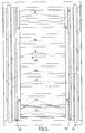
- the ceiling is shown diagrammatically in FIG. 1, for example of a room equipped with a storage structure forming a false ceiling 2 delimited by a lower face 3.
- the device according to the present invention comprises a fixed chassis 4 mounted on the internal face of a planar element generally designated by the reference 5 and consisting of three rectangular panels 6 joined together so as to form a single panel (5 ).
- This panel 5 is suspended and articulated on the structure of the false ceiling 2,3 in accordance with the device described in document EP-A-0182 731.
- the panel 5 is articulated around a fixed horizontal axis 7 and can take two stable positions, one, for which the external face of the panels 6 is horizontal and level with that of the other panels 6 constituting the false ceiling 2,3, the other, illustrated by FIG. 1, for which the panels 6 are vertical.
- An adjustable weight compensation system (not shown) allows switching between the two positions with reasonable effort.
- the fixed frame 4 is constituted, in the embodiment shown, by two elements facing each other in rough form of scale, arranged parallel near the longitudinal edges (fig 5) of the panel 5. These elements 4 thus define two crosspieces or uprights 4a parallel to each other as well as with respect to the panel and at a distance from the latter, of the order of a few tens of centimeters for example, sufficient to allow the accommodation, in the folded position, of the bedding, in the defined volume between said crosspieces 4a and the panel 5.
- angles 9 are secured to each other at their end opposite to the axis of articulation 7 of the panel 5, by means of a rectangular frame 12 articulated at one of its ends around a horizontal axis 13.
- the angles 9 can of course be connected together at their other end.
- the frame 12 is for example made of metal L-shaped angles and receives a bed base symbolized at 14 on which a mattress 15 rests.
- the bed base and the mattress are in several foldable parts.
- the bed base 14 for example a slatted bed base, comprises a frame 16 (fig 3) received in the frame 12 while being held there by any appropriate means, extended by a first part 17, articulated at 17a on the part 16, and by a second part 18, articulated in 18a on the part 17.
- the hinged joints between said parts 16, 17 and 18 allow the folding at right angles as indicated in dashed lines in 17 ′ and 18 ′ of parts 17 and 18, so as to marry the mattress itself consisting of two parts articulated around an axis 20 to allow the flap (15 ′) one on the other of the two parts during the folding of the bedding structure.
- the frame 12 is also provided, at the head of the bedding (axis side 13), with retractable feet 22 provided with height adjustment jacks 23, which can be folded against the underside of the frame 12 around hinges 24 and, at its other end , similar retractable feet 25.
- Compasses 26 are advantageously provided to hold the feet in the deployed position.
- the feet 22, 25 are kept in the folded position by any appropriate means, for example magnets 27 fixed at the desired locations.
- the end of the part 18 of the bed base is also provided with feet 28 with adjustment jacks 23, articulated so as to fall back against the extreme edge of the bed base, parallel to the axis of articulation 19.
- an adjustable weight compensation means such as two gas cylinders 29 arranged parallel to the two angles 9 and anchored, on the one hand, substantially in the central part of the uprights 4a and, on the other hand, at the lower part, in the deployed position of the device, angles 9.
- a stop can be provided, for example a projection integral with the upper end (in the vertical position of the chassis) of the angles 9, ending its race against the slide shoe 8 upper.
- the gas compasses 29 are adjusted according to the weight of the movable assembly so that this assembly (in the position of FIG. 5) is easy to maneuver without great effort, upwards (retraction of the compasses 29) and downwards (extension of the compasses 29) and while remaining in the position we just brought it to.
- the lowering or raising operation of the panel is carried out by gripping the extreme edge of the panel opposite the axis 7.
- panel 5 by joining three consecutive panels 6 is aesthetic. This gives continuity to the visible face 3 of the false ceiling, the location of the bedding not being visible since the three panels 6, once raised, are strictly identical in size and layout, to the adjacent panels of the structure false ceiling, these other panels being assigned to other storage in space 2 and having dimensions much smaller than those necessary for the retraction of the bedding 12, 14, 15.
- the structure 12, 14 may possibly not be provided with folding legs and rest directly on the ground.
- the device of the invention can be applied to sofas (transformable or not) or seats, the frame 12 then supporting the seat part as well as the back part, possibly in association with the movable frame 9.
- the invention is obviously not limited to the embodiment shown and described above, but on the contrary all the variants are covered, in particular as regards the shapes, dimensions and arrangement of the fixed chassis 4, of the mobile chassis 9 and of the frame 12 supporting the bedding or the like.
Abstract
- L'objet de l'invention est un dispositif de déploiement et escamotage en faux-plafond (2) d'une literie (14,15) ou similaire, destiné à s'intégrer dans un système de rangement suspendu comprenant des panneaux (5,6) formant faux-plafond et montés basculants entre deux positions stables, l'une, horizontale, et, l'autre, verticale, caractérisé en ce qu'il est constitué d'un châssis fixe (4) monté sur la face interne d'au moins un desdits panneaux (5), et d'un châssis mobile monté coulissant sur ledit châssis fixe, parallèlement au panneau et à distance de ce dernier et d'un cadre (12) support de literie ou similaire (14,15), monté articulé autour d'un axe (13) parallèle à l'axe d'articulation (7) du panneau (5) à l'extrémité du châssis mobile (9) opposée audit axe d'articulation (7) du panneau. - Application aux literies ou similaires escamotables en faux-plafond.- The object of the invention is a deployment and retraction device in false ceiling (2) of bedding (14,15) or the like, intended to be integrated into a suspended storage system comprising panels (5 , 6) forming false ceilings and mounted tilting between two stable positions, one horizontal and the other vertical, characterized in that it consists of a fixed frame (4) mounted on the internal face at least one of said panels (5), and a movable frame slidingly mounted on said fixed frame, parallel to the panel and at a distance from the latter and from a bedding support frame or the like (14,15 ), mounted articulated about an axis (13) parallel to the axis of articulation (7) of the panel (5) at the end of the movable frame (9) opposite to said axis of articulation (7) of the panel. - Application to bedding or similar retractable false ceiling.
Description
La présente invention a trait à un dispositif de déploiement et escamotage dans une structure en faux-plafond d'une literie, d'un canapé ou similaire.The present invention relates to a device for deployment and retraction in a false ceiling structure of bedding, a sofa or the like.
Plus précisément l'invention concerne un mécanisme de déploiement et escamotage destiné à s'intégrer dans un système de rangement suspendu du type décrit dans le document EP-A-0182 731.More specifically, the invention relates to a deployment and retraction mechanism intended to be integrated into a suspended storage system of the type described in document EP-A-0182 731.
Ce document se rapporte à un dispositif de rangement suspendu à caissons individuels basculants juxtaposés caractérisé en ce qu'il est constitué d'une pluralité de caissons de rangement disposés chacun sur la face supérieure d'un panneau plan rectangulaire ou carré, articulé autour d'un axe parallèle à l'un des côtés longitudinaux et au voisinage de ce dernier, sur deux pièces montées fixes aux deux extrémités latérales du panneau, des moyens étant prévus pour verrouiller les panneaux en position horizontale et limiter leur ouverture vers le bas sensiblement jusqu'à la verticale, les panneaux étant alignés côte à côte suivant une ou deux directions en étant parallèles les uns les autres et à très faible distance sans aucun élément structurel fixe interposé entre eux dans le sens d'alignement orthogonal aux axes de basculement.This document relates to a hanging storage device with juxtaposed tilting individual boxes characterized in that it consists of a plurality of storage boxes each arranged on the upper face of a rectangular or square plane panel, articulated around an axis parallel to one of the longitudinal sides and in the vicinity of the latter, on two parts mounted fixed at the two lateral ends of the panel, means being provided for locking the panels in a horizontal position and limiting their opening downwards substantially up to vertically, the panels being aligned side by side in one or two directions being parallel to each other and at a very short distance without any fixed structural element interposed between them in the direction of alignment orthogonal to the tilt axes.
Un tel dispositif constitue une structure de rangement multiple composable à volonté car susceptible de s'étendre dans deux directions orthogonales pour former, grâce à la seule face inférieure des panneaux juxtaposés en damier, une surface pratiquement continue, en position relevée des caissons de rangement, sans saillie ni décrochement, constituant en elle-même un faux-plafond à la fois esthétique et fonctionnel.Such a device constitutes a multiple storage structure that can be composed at will since it can extend in two orthogonal directions to form, by virtue of the single underside of the panels juxtaposed in checkerboard form, a practically continuous surface, in the raised position of the storage boxes, without protrusion or recess, constituting in itself a false ceiling that is both aesthetic and functional.
Le but de l'invention est d'intégrer dans une telle structure un mécanisme de déploiement d'une literie ou similaire permettant l'escamotage intégral de cette dernière à l'intérieur dudit faux-plafond.The object of the invention is to integrate into such a structure a mechanism for deploying bedding or the like allowing the entire retraction of the latter inside said false ceiling.
A cet effet, l'invention a pour objet un dispositif de déploiement et escamotage en faux-plafond d'une literie ou similaire, destiné à s'intégrer dans un système de rangement suspendu comprenant des panneaux notamment rectangulaires, plans, juxtaposés, formant faux-plafond et montés basculants entre deux positions stables, l'une, horizontale, de fermeture, délimitant ledit faux-plafond et, l'autre, verticale, d'ouverture, caractérisé en ce qu'il est constitué d'un châssis fixe monté sur la face interne d'au moins un desdits panneaux, et d'un châssis mobile monté coulissant sur ledit châssis fixe, parallèlement au panneau et à distance de ce dernier et d'un cadre support de literie ou similaire monté articulé autour d'un axe parallèle à l'axe d'articulation du panneau.To this end, the invention relates to a device for deploying and retracting false ceilings of bedding or the like, intended to be integrated into a suspended storage system comprising panels in particular rectangular, planes, juxtaposed, forming false - suspended ceiling and mounted between two stable positions, one, horizontal, closing, delimiting said false ceiling and, the other, vertical, opening, characterized in that it consists of a fixed chassis mounted on the internal face of at least one of said panels, and of a movable frame mounted to slide on said fixed frame, parallel to and at a distance from the panel and from a bedding support frame or the like mounted articulated around a axis parallel to the axis of articulation of the panel.
Un tel mécanisme permet un déploiement aisé de la literie ou analogue, par simple ouverture d'un panneau de la structure du faux-plafond, descente verticale de l'ensemble châssis mobile - cadre support de literie, puis pivotement de ce dernier cadre pour l'amener en position horizontale .Such a mechanism allows easy deployment of the bedding or the like, by simply opening a panel of the structure of the false ceiling, vertical descent of the movable chassis - bedding support frame, then pivoting of the latter frame for the 'bring it to a horizontal position.
Avantageusement un système de compensation de poids réglable, tel que des vérins à gaz, est interposé entre les châssis fixe et mobile pour faciliter les manoeuvres de monte et baisse de l'ensemble châssis mobile cadre-support le long du châssis fixe.Advantageously, an adjustable weight compensation system, such as gas cylinders, is interposed between the fixed and mobile chassis to facilitate the maneuvers of raising and lowering of the mobile chassis-support-frame assembly along the fixed chassis.
Suivant une autre caractéristique ledit cadre support peut comporter des pieds, de préférence réglables en hauteur, montés articulés sur le cadre de manière à être repliables.According to another characteristic, said support frame may include feet, preferably adjustable in height, mounted articulated on the frame so as to be foldable.
Suivant une autre caractéristique, afin de réduire l'encombrement de l'ensemble, le cadre-support présente une longueur réduite, le sommier ou analogue étant constitué de plusieurs parties articulées repliables.According to another characteristic, in order to reduce the overall dimensions of the assembly, the support frame has a reduced length, the bed base or the like consisting of several foldable articulated parts.
D'autres caractéristiques et avantages ressortiront de la description qui va suivre d'un mode de réalisation du dispositif selon l'invention, description donnée à titre d'exemple uniquement et en regard des dessins annexés sur lesquels :
- - Fig 1 est une vue en élévation latérale d'un dispositif conforme à l'invention en position déployée ;
- - Fig 2 est une vue agrandie en coupe verticale, d'une partie du dispositif de la fig 1 ;
- - Fig 3 est une vue agrandie d'une autre partie du dispositif de la fig 1 ;
- - Fig 4 est une vue en coupe suivant la ligne IV-IV du dispositif de la fig 2, et
- - Fig 5 est une vue de gauche du dispositif de la fig 1, l'ensemble châssis mobile - cadre support étant replié et remonté en position haute vis à vis du châssis fixe.
- - Fig 1 is a side elevational view of a device according to the invention in the deployed position;
- - Fig 2 is an enlarged view in vertical section, of a part of the device of Fig 1;
- - Fig 3 is an enlarged view of another part of the device of Fig 1;
- - Fig 4 is a sectional view along line IV-IV of the device of fig 2, and
- - Fig 5 is a left view of the device of Fig 1, the mobile chassis - support frame assembly being folded and reassembled in the high position with respect to the fixed chassis.
On a représenté schématiquement sur la fig 1 le plafond, par exemple d'une pièce équipée d'une structure de rangement formant un faux-plafond 2 délimité par une face inférieure 3.The ceiling is shown diagrammatically in FIG. 1, for example of a room equipped with a storage structure forming a false ceiling 2 delimited by a
Le dispositif selon la présente invention comprend un châssis fixe 4 monté sur la face interne d'un élément plan désigné d'une manière générale par la référence 5 et constitué de trois panneaux rectangulaires 6 solidarisés entre eux de manière à former un panneau unique (5).The device according to the present invention comprises a
Ce panneau 5 est suspendu et articulé sur la structure du faux-plafond 2,3 conformément au dispositif décrit dans le document EP-A-0182 731.This
En bref, le panneau 5 est articulé autour d'un axe horizontal fixe 7 et peut prendre deux positions stables, l'une, pour laquelle la face externe des panneaux 6 est horizontale et de niveau avec celle des autres panneaux 6 constituant le faux-plafond 2,3, l'autre, illustrée par la Fig 1, pour laquelle les panneaux 6 sont verticaux. Un système de compensation de poids réglable (non représenté) permet de passer entre les deux positions avec un effort raisonnable. Pour plus de détails relatifs à cette structure on pourra se reporter utilement au document cité plus haut.In short, the
Le châssis fixe 4 est constitué, dans le mode de réalisation représenté, par deux éléments en vis à vis en forme approximative d'échelle, disposés parallèlement près des bords longitudinaux (fig 5) du panneau 5. Ces éléments 4 définissent ainsi deux traverses ou montants 4a parallèles entre elles ainsi que vis à vis du panneau et à une distance de ce dernier, de l'ordre de quelques dizaines de centimètres par exemple, suffisante pour permettre le logement, en position repliée, de la literie, dans le volume délimité entre lesdites traverses 4a et le panneau 5.The
Le long des traverses 4a, et plus précisément sur des patins de glissière 8 fixés en regard sur les faces internes des traverses 4a, peut coulisser parallèlement au panneau 5 un châssis mobile constitué, dans le mode de réalisation représenté, par deux cornières parallèles 9. Pour assurer le coulissement des cornières 9 sur les patins 8 et leur retenue (fig 4), les patins présentent sur leurs flancs des bossages 10 pénétrant dans des gorges complémentaires 11 ménagées sur les flancs internes en regard des cornières 9.Along the
Les cornières 9 sont solidarisées entre elles à leur extrémité opposée à l'axe d'articulation 7 du panneau 5, par l'intermédiaire d'un cadre rectangulaire 12 articulé à l'une de ses extrémités autour d'un axe horizontal 13.The
Les cornières 9 peuvent bien entendu être reliées entre elles à leur autre extrémité.The
Le cadre 12 est constitué par exemple de cornières métalliques en L et reçoit un sommier symbolisé en 14 sur lequel repose un matelas 15.The
Dans le mode de réalisation représenté le sommier et le matelas sont en plusieurs parties repliables.In the embodiment shown the bed base and the mattress are in several foldable parts.
Le sommier 14, par exemple un sommier à lattes, comporte un cadre 16 (fig 3) reçu dans le cadre 12 en y étant maintenu par tous moyens appropriés, prolongé par une première partie 17, articulée en 17a sur la partie 16, et par une seconde partie 18, articulée en 18a sur la partie 17. Les articulations à charnières entre lesdites parties 16, 17 et 18 permettent le repliage à angle droit comme indiqué en tiretés en 17′ et 18′ des parties 17 et 18, de manière à épouser le matelas lui-même constitué de deux parties articulées autour d'un axe 20 pour permettre le rabat (15′) l'une sur l'autre des deux parties lors du repliage de la structure de literie.The
L'intérêt de cette structure est la réduction en position repliée de l'ensemble cadre 12 - literie et donc de la longueur des châssis 4 et 9 et de celle du panneau 5. Ceci diminue en conséquence le porte-à-faux de l'ensemble du système en position relevée (21, fig 1) d'escamotage dans le faux-plafond 2.The advantage of this structure is the reduction in the folded position of the frame 12 - bedding assembly and therefore of the length of the
Le cadre 12 est également muni, à la tête de la literie (côté axe 13), de pieds escamotables 22 munis de vérins 23 de réglage en hauteur, rabattables contre la face inférieure du cadre 12 autour de charnières 24 et, à son autre extrémité, de pieds escamotables analogues 25. Des compas 26 sont avantageusement prévus pour maintenir les pieds en position déployée. Les pieds 22, 25 sont maintenus en position repliée par tous moyens appropriés, par exemple des aimants 27 fixés aux endroits désirés.The
L'extrémité de la partie 18 du sommier est également munie de pieds 28 à vérins de réglage 23, articulés de manière à se rabattre contre le bord extrême du sommier, parallèlement à l'axe d'articulation 19.The end of the
Entre le châssis mobile 9 et le châssis fixe 4 est prévu un moyen de compensation de poids, réglable, tel que deux vérins à gaz 29 disposés parallèlement aux deux cornières 9 et ancrés, d'une part, sensiblement dans la partie centrale des montants 4a et, d'autre part, à la partie inférieure, en position déployée du dispositif, des cornières 9.Between the
En position relevée à la verticale de l'ensemble 12,15 et remontée en position haute de l'ensemble 12, 15, 9, tel qu'illustré par la fig 5, ce dernier ensemble est maintenu par tous moyens appropriés de retenue évitant la retombée intempestive dudit ensemble par rotation autour de l'axe 13.In the raised vertical position of the
En position de descente maximale du châssis 9 le long du châssis fixe 4, on peut prévoir une butée, par exemple une saillie solidaire de l'extrémité supérieure (en position verticale du châssis ) des cornières 9, terminant sa course contre le patin de glissière 8 supérieur.In the position of maximum descent of the
Les compas à gaz 29 sont réglés en fonction du poids de l'ensemble mobile de façon que cet ensemble (dans la position de la fig 5) se manoeuvre aisément sans grand effort, vers le haut (rétraction des compas 29) et vers le bas (extension des compas 29) et en demeurant dans la position dans laquelle on vient de l'amener.The gas compasses 29 are adjusted according to the weight of the movable assembly so that this assembly (in the position of FIG. 5) is easy to maneuver without great effort, upwards (retraction of the compasses 29) and downwards (extension of the compasses 29) and while remaining in the position we just brought it to.
Dans cette position de la fig 5, les pieds 22 et 25 étant repliés, le dispositif est prêt à être escamoté dans le faux-plafond 2 par relèvement du panneau 5 et pivotement autour de l'axe 7, l'effort à exercer étant très réduit grâce au système de compensation dont est muni le panneau 5 comme il a été dit plus haut.In this position of fig 5, the
La manoeuvre d'abaissement ou de remontée du panneau s'effectue en agrippant le bord extrême du panneau opposé à l'axe 7.The lowering or raising operation of the panel is carried out by gripping the extreme edge of the panel opposite the axis 7.
L'intérêt de la réalisation du panneau 5 par solidarisation de trois panneaux 6 consécutifs est d'ordre esthétique. On donne ainsi à la face visible 3 du faux-plafond une continuité, l'emplacement de la literie n'étant pas visible puisque les trois panneaux 6, une fois relevés, sont strictement identiques en dimensions et disposition, aux panneaux adjacents de la structure de faux-plafond, ces autres panneaux étant affectés à d'autres rangements dans l'espace 2 et ayant des dimensions nettement inférieures à celles nécessaires pour l'escamotage de la literie 12, 14, 15.The advantage of producing
la structure 12, 14 peut éventuellement ne pas être munie de pieds repliables et reposer directement sur le sol.the
Le dispositif de l'invention peut s'appliquer à des canapés (transformables ou non) ou des sièges, le cadre 12 supportant alors la partie siège ainsi que la partie dossier, éventuellement en association avec le châssis mobile 9.The device of the invention can be applied to sofas (transformable or not) or seats, the
On peut aussi aménager l'espace entre le panneau 5 et le châssis fixe 4 pour y incorporer un dispositif d'éclairage par exemple.We can also arrange the space between the
Enfin, l'invention n'est évidemment pas limitée au mode de réalisation représenté et décrit ci-dessus mais on couvre au contraire toutes les variantes notamment en ce qui concerne les formes, dimensions et agencement du châssis fixe 4, du châssis mobile 9 et du cadre 12 support de la literie ou similaire.Finally, the invention is obviously not limited to the embodiment shown and described above, but on the contrary all the variants are covered, in particular as regards the shapes, dimensions and arrangement of the
Claims (6)
Applications Claiming Priority (2)
| Application Number | Priority Date | Filing Date | Title |
|---|---|---|---|
| FR8710510A FR2618315B1 (en) | 1987-07-22 | 1987-07-22 | DEVICE FOR DEPLOYING AND FALLED CEILING OF BEDDING OR THE LIKE |
| FR8710510 | 1987-07-22 |
Publications (2)
| Publication Number | Publication Date |
|---|---|
| EP0300939A2 true EP0300939A2 (en) | 1989-01-25 |
| EP0300939A3 EP0300939A3 (en) | 1989-03-15 |
Family
ID=9353518
Family Applications (1)
| Application Number | Title | Priority Date | Filing Date |
|---|---|---|---|
| EP88450028A Withdrawn EP0300939A3 (en) | 1987-07-22 | 1988-07-22 | Device für unfolding and hiding a bed or the like in a false ceiling |
Country Status (7)
| Country | Link |
|---|---|
| US (1) | US4853989A (en) |
| EP (1) | EP0300939A3 (en) |
| JP (1) | JPS6449509A (en) |
| KR (1) | KR890001492A (en) |
| AU (1) | AU615457B2 (en) |
| FR (1) | FR2618315B1 (en) |
| PT (1) | PT88061A (en) |
Cited By (1)
| Publication number | Priority date | Publication date | Assignee | Title |
|---|---|---|---|---|
| EP0630600A1 (en) * | 1993-06-25 | 1994-12-28 | ETABLISSEMENTS COMPIN Société Anonyme dite: | A bed or sleeping berth structure retractable in a ceiling |
Families Citing this family (8)
| Publication number | Priority date | Publication date | Assignee | Title |
|---|---|---|---|---|
| US6523194B2 (en) * | 2001-06-18 | 2003-02-25 | Keith B. Smith | Knee wall bed |
| US6698040B1 (en) * | 2002-07-19 | 2004-03-02 | Oscar Acevedo | Retractable bed |
| US6829791B2 (en) | 2003-01-27 | 2004-12-14 | Emmett James Roepke | System and method for retractable furniture unit |
| US8136181B2 (en) | 2003-01-27 | 2012-03-20 | Emmett James Roepke | System and method for retractable furniture unit |
| WO2005012156A2 (en) * | 2003-07-31 | 2005-02-10 | Happijac Company | System and method for moving objects |
| CN101898626B (en) * | 2010-07-26 | 2013-03-27 | 江苏海陆科技股份有限公司 | Invisible bed for ship |
| US8402700B2 (en) | 2010-12-27 | 2013-03-26 | David R. Hall | Wall assembly comprising panels configured to reside in an overhead structure |
| US9656590B2 (en) | 2014-05-15 | 2017-05-23 | Lippert Components, Inc. | Bed lift mounting member |
Citations (1)
| Publication number | Priority date | Publication date | Assignee | Title |
|---|---|---|---|---|
| NL7415980A (en) * | 1974-12-09 | 1976-06-11 | Johan Petrus Busio | Adaptable dwelling house with movable walls - has wall swinging upwards on axis at ceiling level |
Family Cites Families (9)
| Publication number | Priority date | Publication date | Assignee | Title |
|---|---|---|---|---|
| CA475988A (en) * | 1951-08-14 | Moses Dorton John | Wall beds | |
| US67494A (en) * | 1867-08-06 | burnett | ||
| US1300694A (en) * | 1918-06-20 | 1919-04-15 | Robert W Bostwick | Disappearing bed. |
| US2526562A (en) * | 1945-09-13 | 1950-10-17 | Kelcon Corp | Berth construction |
| US2645787A (en) * | 1950-12-12 | 1953-07-21 | Will Victor Ray | Ceiling bed |
| US3829912A (en) * | 1971-09-01 | 1974-08-20 | Flexsteel Industries | Retractable bed assemblies |
| US4243260A (en) * | 1979-07-25 | 1981-01-06 | Darrell Gieseking | Convertible bed for pick-up truck camper or the like |
| FR2572761B1 (en) * | 1984-11-05 | 1988-06-24 | Duran Gilbert | ARTICULATED STORAGE DEVICE FOR USING THE TOP OF A VOLUME |
| US4699437A (en) * | 1985-05-14 | 1987-10-13 | Genereaux Eugene P | Apparatus for storing objects |
-
1987
- 1987-07-22 FR FR8710510A patent/FR2618315B1/en not_active Expired - Lifetime
-
1988
- 1988-07-19 KR KR1019880009004A patent/KR890001492A/en not_active Application Discontinuation
- 1988-07-20 JP JP63181435A patent/JPS6449509A/en active Pending
- 1988-07-21 AU AU19775/88A patent/AU615457B2/en not_active Expired - Fee Related
- 1988-07-21 PT PT88061A patent/PT88061A/en not_active Application Discontinuation
- 1988-07-22 US US07/222,923 patent/US4853989A/en not_active Expired - Fee Related
- 1988-07-22 EP EP88450028A patent/EP0300939A3/en not_active Withdrawn
Patent Citations (1)
| Publication number | Priority date | Publication date | Assignee | Title |
|---|---|---|---|---|
| NL7415980A (en) * | 1974-12-09 | 1976-06-11 | Johan Petrus Busio | Adaptable dwelling house with movable walls - has wall swinging upwards on axis at ceiling level |
Cited By (3)
| Publication number | Priority date | Publication date | Assignee | Title |
|---|---|---|---|---|
| EP0630600A1 (en) * | 1993-06-25 | 1994-12-28 | ETABLISSEMENTS COMPIN Société Anonyme dite: | A bed or sleeping berth structure retractable in a ceiling |
| FR2706750A1 (en) * | 1993-06-25 | 1994-12-30 | Compin Ets | |
| US5461735A (en) * | 1993-06-25 | 1995-10-31 | Establissments Compin | Bed or cot structure which can be retracted into a ceiling |
Also Published As
| Publication number | Publication date |
|---|---|
| AU1977588A (en) | 1989-01-27 |
| US4853989A (en) | 1989-08-08 |
| FR2618315B1 (en) | 1990-01-05 |
| KR890001492A (en) | 1989-03-27 |
| JPS6449509A (en) | 1989-02-27 |
| AU615457B2 (en) | 1991-10-03 |
| PT88061A (en) | 1989-06-30 |
| EP0300939A3 (en) | 1989-03-15 |
| FR2618315A1 (en) | 1989-01-27 |
Similar Documents
| Publication | Publication Date | Title |
|---|---|---|
| EP0426742A1 (en) | Collapsible table. | |
| WO1991008806A1 (en) | Mobile artificial climbing wall | |
| FR2744681A1 (en) | FOLDABLE AND MOBILE GRADIN SYSTEM | |
| EP0300939A2 (en) | Device für unfolding and hiding a bed or the like in a false ceiling | |
| CA2022441A1 (en) | Pliable building structure | |
| FR2466217A1 (en) | Ironing board - fits to wall, and adopts two positions | |
| EP0528725B1 (en) | Mobile boxing ring | |
| EP0880444B1 (en) | Folding platform and vehicle provided therewith | |
| FR2876668A1 (en) | Container for storing and packaging e.g. components, has operating unit liberating locking device from posts, and carrying structure with ends connected to posts in articulated manner to support and to control descent of ends towards base | |
| FR2573706A1 (en) | Living compartment of the foldable and/or dismantlable type, for example a caravan | |
| FR2497449A1 (en) | TRANSFORMABLE BED SOFA | |
| EP2330255B1 (en) | Extensible, transportable habitable cell | |
| EP3836878B1 (en) | Demountable bed transport trolley | |
| FR2462888A1 (en) | Fold away bunk beds - comprise two folding mattress basesssliding cut from frame, with top and side panels and stabilisers | |
| FR2935318A1 (en) | Retractable shelf arrangement for panel van, has shelf whose board has front part suspended by arms to slider in horizontal position, and arms placed in nearly horizontal position when board is in vertical position | |
| FR3101088A1 (en) | Scaffolding | |
| EP1053705A1 (en) | Hospital bed having side guards | |
| FR2760612A1 (en) | Sofa or armchair convertible into bed | |
| WO2003092438A2 (en) | Extensible stools | |
| FR3013272A1 (en) | NEW TYPE SHELTER | |
| FR2768909A1 (en) | Sofa transformable into bed and unfolded transversally | |
| EP0305309A1 (en) | Device extendible from and retractable into the false ceiling of a wardrobe | |
| FR2528298A1 (en) | Convertible bed settee mechanism - has extendable three piece mobile frame inside fixed casing with sliding panels | |
| FR2528297A1 (en) | Convertible bed settee mechanism - has mobile front and rear mattresses linked to rigid base frame allowing 180 deg. swivel of front mattress | |
| FR2523424A1 (en) | Height adjustable frame for table - can be tilted and adjusted in height, and consists of base with two legs |
Legal Events
| Date | Code | Title | Description |
|---|---|---|---|
| PUAI | Public reference made under article 153(3) epc to a published international application that has entered the european phase |
Free format text: ORIGINAL CODE: 0009012 |
|
| AK | Designated contracting states |
Kind code of ref document: A2 Designated state(s): AT BE CH DE ES GB GR IT LI LU NL SE |
|
| PUAL | Search report despatched |
Free format text: ORIGINAL CODE: 0009013 |
|
| AK | Designated contracting states |
Kind code of ref document: A3 Designated state(s): AT BE CH DE ES GB GR IT LI LU NL SE |
|
| 17P | Request for examination filed |
Effective date: 19890908 |
|
| 17Q | First examination report despatched |
Effective date: 19901005 |
|
| STAA | Information on the status of an ep patent application or granted ep patent |
Free format text: STATUS: THE APPLICATION IS DEEMED TO BE WITHDRAWN |
|
| 18D | Application deemed to be withdrawn |
Effective date: 19920204 |