EP0300588B1 - Cell culturing apparatus and method - Google Patents
Cell culturing apparatus and method Download PDFInfo
- Publication number
- EP0300588B1 EP0300588B1 EP88301936A EP88301936A EP0300588B1 EP 0300588 B1 EP0300588 B1 EP 0300588B1 EP 88301936 A EP88301936 A EP 88301936A EP 88301936 A EP88301936 A EP 88301936A EP 0300588 B1 EP0300588 B1 EP 0300588B1
- Authority
- EP
- European Patent Office
- Prior art keywords
- culturing
- containers
- infeed
- discharge
- lifter
- Prior art date
- Legal status (The legal status is an assumption and is not a legal conclusion. Google has not performed a legal analysis and makes no representation as to the accuracy of the status listed.)
- Expired - Lifetime
Links
- 238000012258 culturing Methods 0.000 title claims description 244
- 238000000034 method Methods 0.000 title description 6
- 230000007246 mechanism Effects 0.000 claims description 99
- 230000033001 locomotion Effects 0.000 claims description 34
- 230000036544 posture Effects 0.000 claims description 33
- 239000001963 growth medium Substances 0.000 claims description 28
- 238000003780 insertion Methods 0.000 claims description 5
- 230000037431 insertion Effects 0.000 claims description 5
- 238000007599 discharging Methods 0.000 claims description 4
- 230000002093 peripheral effect Effects 0.000 claims description 2
- 230000001105 regulatory effect Effects 0.000 claims 1
- 210000004027 cell Anatomy 0.000 description 37
- 239000007788 liquid Substances 0.000 description 23
- 230000002159 abnormal effect Effects 0.000 description 10
- 238000006073 displacement reaction Methods 0.000 description 9
- 238000012546 transfer Methods 0.000 description 9
- 230000005540 biological transmission Effects 0.000 description 6
- 238000004113 cell culture Methods 0.000 description 6
- 238000005096 rolling process Methods 0.000 description 6
- 238000007689 inspection Methods 0.000 description 5
- 238000011081 inoculation Methods 0.000 description 4
- 239000000126 substance Substances 0.000 description 4
- 230000005856 abnormality Effects 0.000 description 3
- 230000008859 change Effects 0.000 description 3
- 238000011109 contamination Methods 0.000 description 3
- 208000037805 labour Diseases 0.000 description 3
- 230000002503 metabolic effect Effects 0.000 description 3
- 230000002441 reversible effect Effects 0.000 description 3
- QGZKDVFQNNGYKY-UHFFFAOYSA-N Ammonia Chemical compound N QGZKDVFQNNGYKY-UHFFFAOYSA-N 0.000 description 2
- 238000004140 cleaning Methods 0.000 description 2
- 238000010276 construction Methods 0.000 description 2
- 210000004748 cultured cell Anatomy 0.000 description 2
- 238000001514 detection method Methods 0.000 description 2
- 230000005484 gravity Effects 0.000 description 2
- JVTAAEKCZFNVCJ-UHFFFAOYSA-N lactic acid Chemical compound CC(O)C(O)=O JVTAAEKCZFNVCJ-UHFFFAOYSA-N 0.000 description 2
- 239000002609 medium Substances 0.000 description 2
- 244000005700 microbiome Species 0.000 description 2
- 230000008569 process Effects 0.000 description 2
- 238000012545 processing Methods 0.000 description 2
- 230000001737 promoting effect Effects 0.000 description 2
- 230000002040 relaxant effect Effects 0.000 description 2
- 241000233866 Fungi Species 0.000 description 1
- 230000004308 accommodation Effects 0.000 description 1
- 229910021529 ammonia Inorganic materials 0.000 description 1
- 210000004102 animal cell Anatomy 0.000 description 1
- 230000001174 ascending effect Effects 0.000 description 1
- 230000004323 axial length Effects 0.000 description 1
- 244000052616 bacterial pathogen Species 0.000 description 1
- 238000007664 blowing Methods 0.000 description 1
- 230000008878 coupling Effects 0.000 description 1
- 238000010168 coupling process Methods 0.000 description 1
- 238000005859 coupling reaction Methods 0.000 description 1
- 230000003247 decreasing effect Effects 0.000 description 1
- 230000000994 depressogenic effect Effects 0.000 description 1
- 238000010586 diagram Methods 0.000 description 1
- 208000015181 infectious disease Diseases 0.000 description 1
- 230000002458 infectious effect Effects 0.000 description 1
- 238000002347 injection Methods 0.000 description 1
- 239000007924 injection Substances 0.000 description 1
- 235000014655 lactic acid Nutrition 0.000 description 1
- 239000004310 lactic acid Substances 0.000 description 1
- 238000009630 liquid culture Methods 0.000 description 1
- 239000000463 material Substances 0.000 description 1
- 230000004048 modification Effects 0.000 description 1
- 238000012986 modification Methods 0.000 description 1
- 230000000050 nutritive effect Effects 0.000 description 1
- 230000004044 response Effects 0.000 description 1
- 230000000007 visual effect Effects 0.000 description 1
Images









Classifications
-
- C—CHEMISTRY; METALLURGY
- C12—BIOCHEMISTRY; BEER; SPIRITS; WINE; VINEGAR; MICROBIOLOGY; ENZYMOLOGY; MUTATION OR GENETIC ENGINEERING
- C12M—APPARATUS FOR ENZYMOLOGY OR MICROBIOLOGY; APPARATUS FOR CULTURING MICROORGANISMS FOR PRODUCING BIOMASS, FOR GROWING CELLS OR FOR OBTAINING FERMENTATION OR METABOLIC PRODUCTS, i.e. BIOREACTORS OR FERMENTERS
- C12M27/00—Means for mixing, agitating or circulating fluids in the vessel
- C12M27/10—Rotating vessel
- C12M27/12—Roller bottles; Roller tubes
-
- C—CHEMISTRY; METALLURGY
- C12—BIOCHEMISTRY; BEER; SPIRITS; WINE; VINEGAR; MICROBIOLOGY; ENZYMOLOGY; MUTATION OR GENETIC ENGINEERING
- C12M—APPARATUS FOR ENZYMOLOGY OR MICROBIOLOGY; APPARATUS FOR CULTURING MICROORGANISMS FOR PRODUCING BIOMASS, FOR GROWING CELLS OR FOR OBTAINING FERMENTATION OR METABOLIC PRODUCTS, i.e. BIOREACTORS OR FERMENTERS
- C12M23/00—Constructional details, e.g. recesses, hinges
- C12M23/48—Holding appliances; Racks; Supports
-
- Y—GENERAL TAGGING OF NEW TECHNOLOGICAL DEVELOPMENTS; GENERAL TAGGING OF CROSS-SECTIONAL TECHNOLOGIES SPANNING OVER SEVERAL SECTIONS OF THE IPC; TECHNICAL SUBJECTS COVERED BY FORMER USPC CROSS-REFERENCE ART COLLECTIONS [XRACs] AND DIGESTS
- Y10—TECHNICAL SUBJECTS COVERED BY FORMER USPC
- Y10S—TECHNICAL SUBJECTS COVERED BY FORMER USPC CROSS-REFERENCE ART COLLECTIONS [XRACs] AND DIGESTS
- Y10S435/00—Chemistry: molecular biology and microbiology
- Y10S435/809—Incubators or racks or holders for culture plates or containers
Definitions
- the present invention relates to a cell culturing apparatus and call culturing method for culturing zooblast or animal cell, microorganizm and fungus, and plant structural piece.
- culture medium is supplied to a culturing container such as a roller bottle and a tray etc., and cell is inoculated thereon. Thereafter, such culturing container is placed in a culturing rack at a constant temperature for a predetermined period of time for promoting the cell cultivation. Upon completion of the cultivation, the culturing container is discharged from the culturing rack, for collecting cultured cell and its metabolic substance.
- Another object of this invention is to provide such apparatus and method capable of performing efficient processing to culturing containers while preventing a personnel from contamination with bacille.
- a cell culturing apparatus which uses culturing containers containing therein cells and culture medium for cell culturing, characterised by: a rack supporting apparatus comprising a loop tracking means and a plurality of culturing racks each connected one after another in series and adapted to travel on said loop tracking means, each of said racks accommodating therein said culturing containers for cell culturing; an infeed station disposed at a position alongside said loop tracking means for automatically supplying said culturing containers into said culturing racks, said infeed station comprising an infeed lifter which is vertically movable for temporarily mounting thereon said culturing containers in order to supply the culturing containers into said culturing racks, a posture changing mechanism comprising arcuate guide members having a lower end positioned in the vicinity of said infeed conveyor and an upper end directed toward said infeed lifter, an infeed pusher for pushing predetermined numbers of said culturing containers carried on said infeed conveyor toward said guide members, means
- the posture changing mechanism may comprise arcuate guide members having a lower end positioned in the vicinity of said infeed conveyor and an upper end directed toward said infeed lifter, a chain disposed along said arcuate guide members, said chain integrally providing a support member, and an infeed pusher for pushing predetermined numbers of said culturing containers carried on said infeed conveyor toward said guide members, said support member carrying said containers being pushed by said infeed pusher and moving the same along said guide members, gradually inclining said containers toward a horizontal posture.
- the posture changing mechanism may comprise arcuate guide members having lower end positioned in the vicinity of said infeed conveyor and an upper end directed toward said infeed lifter, an infeed pusher for pushing predetermined numbers of said culturing containers carried on said infeed conveyor toward said guide members, a container infeed unit adapted to move said culturing containers along said arcuate guide members causing said culturing containers to fall from their upstanding posture to a horizontal posture, said container infeeding unit comprising; a supporting plate positioned outside said arcuate guide members for supporting the bases of said culturing containers; support arms supporting said supporting plate and swingably movable between their horizontal and vertical postures aid containers supported on said supporting plate being gradually inclined toward a horizontal posture during their travel on said guide members by an upward swinging movement of said support arms.
- a cell culturing apparatus is adapted to perform cell culturing and exchange with respect to rotary cylinder type cell culturing containers (roller bottles) 1 in which culture medium and cells are contained.
- the cell culturing apparatus generally includes a handling station 2, an infeed station 4, a rack supporting apparatus S including a rotary type culturing racks 5, and a discharge station 6. In the handling station, filling of culture medium into the roller bottles, cell inoculation, and rinsing of the roller bottles are performed.
- the roller bottles containing therein the cells and culture medium are automatically supplied from the handling station 2 to the infeed station 4 by an infeed conveyor 3, and the culturing containers 1 are transferred from the infeed station to the rotary culturing racks 5 which are movable on a loop path of the rack supporting apparatus S. During the travel of the racks, cell culturing is promoted in the roller bottles 1. The culturing containers 1 are then automatically discharged from the culturing racks 5 to the discharge station 2 and are transferred to the handling station 2 by a discharging conveyor 7. In the handling station 2, the cultured cells are removed from the containers 1, and the bottles are subjected to insertion of new cells and cluture medium.
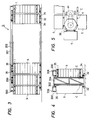
- the rack supporting apparatus S connects a plurality of racks 5 one after another in the loop tracking path.
- a base frame 204 vertically extend at longitudinal ends of the loop path. and hexagonal sprokects 36, 36 are disposed at the longitudinal ends.
- a guide rail 202 is installed at the upper lateral sides of the base frame 204.
- Each of the racks 5 is provided with a roller 35 at its upper portion thereof which roller 35 is engageable with the guide rail 202.
- a contact rod 200 extends from each upper surface of the racks 5.
- the contact rod 200 is in contact with an electrical power supply unit 206 extending from the upper portion of the vertical frame 204. As shown in Figs.
- the power supply unit 206 and the contact rod 200 serve to supply electrical current to a motor 39 for rotating rollers 41 which support the culturing containers and rotate the culturing containers about their axes in the culturing rack 5.
- the motor 39 and the rollers 41 will be described in detail later.
- Each of the culturing racks 5 has a lower surface provided with a roller 34 which runs on a rail 32 installed on a floor.
- elongated chain C is fixedly secured to a lower inside face of each of the racks 5.
- Each of the chains C is connected together by a pin a.
- Each of the pins a is engageable with a recess 36a formed at a corner portion of the hexagonal sprocket 36.
- the elongated chain and the recess 36a of the sprocket 36 define a temporarily stational position of the rack 5 as shown in Fig. 5 when one of the racks 5 is at a position completely confronting the one side of the sprocket 36.
- the sprocket 36 is connected to a drive motor M through an endless chain 203. Upon rotation of the motor M, each of the culturing racks 5 is displaceable on a loop tracking rail 32.
- a star wheel 8 is disposed which has five recesses successively formed on the circumferential surface thereof so as to provide a predetermined distance by every five culturing containers and to simultaneously supply a group of the five culturing containers 1 into a single rack 5.
- Each of the rack stages can receive therein five culturing containers 1 from the infeed station 4, and two culturing racks 5 confront the infeed station, so that ten culturing containers 1 can be simultaneously transferred into the culturing racks 5.
- the infeed station 4 generally includes a posture changing mechanism 9, an infeed lifter 10 and a push-out mechanism 11.
- the posture changing mechanism is adapted to fall down the upstanding containers 1.
- the infeed lifter 10 mounts thereon the two containers oriented in horizontal direction and axially alinged with each other, and moves the two containers in vertical direction.
- the push-out mechanism 11 is disposed on the infeed lifter 10 and is adapted to push the culturing containers 1 toward the culturing racks 5.
- the push-out mechanism is vertically movable in accordance with the vertical movement of the infeed lifter 10, while the collapsing mechanism 9 is not displacable in vertical direction.
- the posture changing mechanism 9 is disposed opposite the culturing racks 5 with respect to the infeed conveyor 3, and includes an infeed pusher 12, a swing arm 14, a cam member 15, guide members 16a and a chain 17.
- the infeed pusher 12 has a longitudinal center portion 12a rotatably supported so as to simultaneously fall down ten upstanding culturing containers 1 toward the culturing racks 5.
- the swing arm 14 has one end 14a connected to the end of the infeed pusher 12 through a linking rod 13, and another end 14b rotatably supported. The intermediate portion of the swing arm 14 is in contact with the cam member 15 so as to provide pivotal movement of the swing arm 14, to thereby swing the infeed pusher 12 about the pivot portion 12a.
- Each of the guide members 16a has a quadrant shape and has triangular cross-section. Neighbouring two guide members define a triangular valley portion on which the culturing container is supported.
- the chain 17 is driven along the arcuate path of the guide member 16a, and has a dog (support plate) 17a extending outwardly from the chain 17.
- the dog 17a supports bottom portion of each of the containers 1, and the containers change their angular orientation by 90 degrees from upstanding state to lying state during their travel along the guide members 16a.
- the lying containers are then supplied to an upper surface of the infeed lifter 10.
- the guide members 16a do not extend in parallelism from one another, but extend obliquely so that spaces defined between the nieghbouring guide members 16a are gradually increased toward the infeed lifter 10. Since a plurality of guide members 16b (Fig. 8) provided on the infeed lifter 10 are disposed separately at a pitch, two neighbouring containers 1 are held separately from each other (Fig. 9).
- the infeed lifter 10 can be vertically movable, so that the containers 1 mounted thereon are brought into a position coincident with the vertical position of the desired stage of the rack 5. At the upwardly displaced position of the lifter 10, the containers 1 are transferred into the rack 5.
- the guide members 16b are disposed in alignment with the guide members 16a, and, a transferring plate 18 is disposed at a space defined between the neighbouring guide members 16b.
- Each of the transferring plates 18 is provided with a recessed portion 18a having arcuate cross-section for avoiding displacement of the containers in radial direction thereof when the culturing container 1 is displaced from the infeed lifter 10 to the culturing rack 5 by means of the push-out mechanism 11.
- the transferring plate 18 has a tip end portion 18b provided with accute edge.
- the transferring plate 18 is movable toward the culturing racks 5 in longitudinal direction of the plate 18 by a drive cylinder 19.
- the infeed lifter 10 also includes a infeed stop member 20 at a position in confrontation with the transferring plate 18 so as to restrain frontward displacement of the culturing containers 1. Further, a power cylinder 21 (Fig. 15) is provided to vertically move the infeed stop member 20 so as to selectively provide free movement of the container 1.
- the push-out mechanism 11 is shown in Figs. 8 throu 10.
- the push-out mechanism 11 includes an infeed slider 23, a nut 24, a ball screw 25, a pulley 26, a motor 27, an infeed member 28, and a power cylinder 29.
- the infeed slider 23 is slidingly movable toward the culturing racks 5 on a guide rail 22 installed on the upper surface of the infeed lifter 10.
- the nut 24 is integrally provided to the infeed slider 23, and is threadingly engaged with the ball screw 25.
- the ball screw 25 has one end portion provided with the pulley 26 which is rotatable by the motor 27 through an endless belt.
- the infeed member 28 is positioned integraly with and in front of the infeed slider 23 and is adapted to push the bottom of the rear culturing container 1 of the axially aligned two containers.
- the cylinder 29 is adapted to move the infeed member 28 in vertical direction.
- front and rear imply the closer and farrer positions with respect to the racks 5, respectively.
- the infeed slider 23 is slidingly moved toward the culturing racks 5, so that the axially aligned two containers mounted on the infeed lifter 10 are urged toward the racks 5 by the infeed member 28.
- Infeed operation of the culturing containers 1 is carried out as follows: Firstly, the infeed convevor 3 and the star wheel 8 are operated in order to supply two groups of containers 1, each group having five containers, to a given position in front of the infeed pusher 12 of the posture changing mechanism 9 and on the infeed conveyor 3. After acknowledgement of these containers at the given position, the movement of the infeed conveyor 3 is suspended.
- This two container groups can also be prepared by an alternative operation shown in Fig. 13. That is, movement of the leading container 1 is stopped by a stopping plate 300, and five containers of the first group are detected by a sensor 301. Upon this detection, a first stop unit 303 positioned adjacent the sensor 301 is operated to prevent the sixth container from its moving. Then, the succeeding four containers of the second group are detected by a sensor 303. When the another five containers of the second group are detected, a second stop unit 304 is operated to prevent succeeding eleventh containers from moving. Therefore, two groups of the containers (totally ten containers) are aligned in front of the posture changing mechanism 9.
- the cam member 15 is rotated to allow the infeed pusher 12 to swing toward the guide members 16a, so that totally ten containers 1 are fallen down onto the guide members 16a.
- the chain 17 is driven to a first direction to simultaneously slidably move the ten containers 1 along the guide members 16a, so that the upstanding containers 1 are horizontally laying on the guide members 16b of the infeed lifter 10.
- each of the container bottoms is held by the dog 17a of the chain 17 and are moved toward the rear portion of the infeed lifter 10 along the guide members 16a.
- subsequent ten containers are introduced onto the guide members 16a and transferred onto the guide members 16b, during which each of the rear bottom ends of the already introduced ten containers are depressed by each of the front ends of the subsequent containers.
- two containers are axially aligned on the upper surface of the infeed lifter 10.
- a cap 1a of the rear container 1 is inserted into a recessed portion 1b of a front container 1, so that the two containers are integrally aligned on the guide member 16b as shown in Figs. 8 and 14.
- the above operations are not interefered by the feed member 28, since the member 28 is provisionally displaced at its ascent position.
- the infeed member 28 When two axially aligned containers are brought into the laying position, the infeed member 28 is moved to its descent position by the extension of the cylinder 29, and upon acknowledgement of the descent position, the infeed slider 23 is moved frontwardly toward the culturing racks 5.
- the infeed member 28 By the movement of the infeed slider 23, the infeed member 28 also moves to the same direction, so that the bottom portion of the rear container 1 of the axially aligned two containers are pushed by the infeed member 28. As a result, the two containers are moved toward the culturing racks 5.
- the infeed stop member 20 positioned in front of the containers is provisionally displaced at its ascent position. Therefore, the front end of the front container 1 is brought into abutment with the stop member 20 for positional adjustment. Concurrently, the movement of the infeed slider 23 is terminated.
- each of the containers 1 is supported by the guide members 16b, while the front end of the front container 1 is in abutment with the infeed stop member 20 and the rear end of the rear container 1 is in abutment with the feed member 28. Therefore, each of the containers 1 is held at stationary state in the infeed lifter 10 without any axial and lateral displacement. Such non-shiftable containers are then moved to their ascent position by the upward movement of the infeed lifter 10 by a vertical height coincident with that of the desired one of the stages of the rack 5 into which the containers are to be inserted.
- each of the transferring plates 18 extends along an intermediate space defined between adjacent two rollers 41 and 41. Even through each of the rollers 41 is provided with two flanges 45, 45 at two front and rear sides thereof, the rear flange 45 does not prevent the transferring plate 18 from extending into the space and from moving between the rollers 41 and 41, because of the above-mentioned positional relationship between the rollers 41 and the plate18.
- the forward movement of the transferring plate 18 is terminated.
- the infeed feeder 22 is moved frontwardly (toward the culturing rack 5) to slidingly move the culturing containers with respect to the guide plates 16b, so that the containers 1 are brought into the positions of the rollers 41.
- the containers are supported by a recessed portion 18a of the transferring plate 18. Therefore, the containers can be smoothly transferred without their lateral displacement. Futher, the transferring plate 18 prevents the front end of the container from abutting against the flange 45 of the roller 41.
- the infeed member 28 prevents the container 1 from axially moving rearwardly due to the retracting movement of the transferring plate 18. Instead, the containers are dropped onto the rollers 41 and 41, and are supported thereby. Further, since the front end of the infeed member 28 is positioned frontwardly with respect to the flange 45, the rear end of the rear container 1 is also droppingly positioned in front of the flange 45. As a result, the containers 1 are suppored by the flange 45 and the stop member 46 without any axial displacement. Such successive operations are performed without any trouble.
- the infeed slider 23 is moved rearwardly (toward the posture changing mechanism), and the infeed lifter 10 is moved to its origianl descent position for receiving new ten containers 1 therein.
- the infeed lifter 10 is again moved upwardly to a predetermined new stage of the rack 5 for inserting the containers to the selected stage of the rack 5.
- Such infeed operations are repeatedly carried out, and accordingly, completed is the insertion of the culturing containers into the culturing racks 5 by means of the infeed station 4.
- the infeed station 400 generally includes a posture changing mechanism 450 (corresponding to the posture changing mechanism 9 of the first embodiment), and a push-out mechanism 406 (corresponding to the push-out mechanism 11 of the first embodiment).
- the posture changing mechanism 450 comprises an infeed pusher 403, the guide member 401, a container supporting unit 404 and a container infeeding unit 402 (corresponding to the push-out mechanism 11 of the first embodiment).
- the infeed pusher 403 is adapted to push and fall down the containers on the infeed conveyor 3 toward the guide members 401.
- the container infeeding unit 402 is adapted to supply containers 1 along guide members 401 into the infeed lifter 10 by reciprocally swingable rotation.
- the container supporting unit 404 is protrudable to the upper space of the conveyor 3 to support side walls of the containers 1 for preventing the containers from their falling down on the conveyor 3 during their state shown in Fig. 13, when ten containers are arranged in line with their upstanding positions on the conveyor 3.
- the push-out mechanism 406 is provided on the infeed lifter 10, and is slidable on a slide surface 405. The push-out mechanism 406 pushes the containers lying on a horizontal portion of the guide member 401 and on the infeed lifter 10 toward predetermined stage of the culturing rack 5 disposed at left margin of Fig. 18.
- the container infeeding unit 402 includes a supporting plate 407, support arms 407a, and a crank mechanism 408.
- the supporting plate 407 extends in a direction across the guide members 401 for supporting bottom portions of the containers at a position outside the guide members 401.
- the support arms 407a are provided at the opposite ends of the supporting plate 407.
- the support arms 407a are operably connected to the crank mechanism 408, so that the support arms 407a are reciprocally rotatable within angularly 90 degrees between horizontal position and vertical position as shown by solid line and two-dotted chain line.
- the crank mechanism 408 includes first, second and third links 409,410 and 411.
- the third link 411 is rotated together with the rotation of a first gear wheel 412 which is in meshing engagement with a second gear wheel 413 drivingly rotated by a motor 414 through a power transmission belt.
- the infeed pusher 403 includes a push rod member 415, first swing arms 416, a second swing arm 417,and a cylinder 418.
- the push rod member 415 extends in a transverse direction of the overall device and has a length larger than the outer diameters of the ten containers, so that upstanding containers can be pushed simultaneously by the push rod member 415.
- Each of the first swing arms 416 has an upper end connected to the each end of the push rod member 415, and a lower end connected to a lower end of the second swing arm 417.
- the upper end of the second swing arm 417 is connected to the cylinder 418.
- the container supporting unit 404 is disposed between the infeed pusher 403 and the container infeeding unit 402.
- the container supporting unit 404 includes a container supporting plate 419 projecting in vertical direction and extending in transverse direction of the overall device, and a cylinder 420 for moving the supporting plate 419 in vertical direction.
- the container supporting plate 419 is maintained at its ascent position, so that it extends in parallel with the rows of the guide members 401 until the upstandingly oriented ten containers on the infeed conveyor 3 are aligned in line without offset of one or several ones of the containers. That is, as shown in Fig. 13, the containers 1 are subjected to force which restrains their travel on the infeed convevor 3 by the stop plate 300.
- the containers 1 on the convevor 3 are urged to be in close contact with each other.
- containers may be fallen down, and dropped from the conveyor 3.
- the container supporting plate 419 is disposed.
- the container supporting plate 419 is retracted to its descent position when the infeed pusher 403 urges the containers toward the guide members 401, so that the pushing operation by the push rod member 415 is not disturbed by the container supporting plate 419.
- the push-out mechanism 406 includes a slide frame 430 slidingly movable on a slide surface 405, an infeed member 431 swingably provided on the slide frame 430 for abutting the bottom surface of the container 1 and pushing the same, and a power cylinder 432 for moving the slide frame 430.
- the infeed member 431 is urged toward a direction for providing its vertical position (operable position) shown in a chain line by biasing force of a spring 433.
- the infeed member 431 When the infeed member 431 is in a position shown by the solid line, the infeed member 431 abuts a stop member 434 protruding from the frame member of the infeed lifter 10, so that the infeed member 431 is maintained at its inoperable position where the infeed member 431 does not prevent the containers running along the guide members 401 from their moving toward the culturing rack 5. That is, if the cylinder rod of the cylinder 432 is extended, the infeed member 431 is moved away from the stop member 434. Therefore, the infeed member 431 is rotated to a vertical operable position shown by the chain line by the biasing force of the spring 433. As a result, containers on the horizontal portion of the guide members 401 and on the infeed lifter 10 are pushed toward the rack 5 by the vertically oriented infeed member 431.
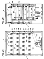
- the culturing racks 5 are assembled at internal space of rack frame 31 of the rack supporting apparatus S as shown in Figs.19 thru 25.
- a rotation mechanism 37 for rotating the culturing container 1 about its axis and for promoting culturing of the cells contained therein.
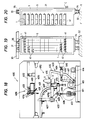
- the rotation mechanism 37 includes a motor 39, a deceleration unit 38 connected to the motor 39, a rotary shafts 40 rotatable by the rotation of the motor 39, and rollers 41 rotatable by the rotary shafts 40, the rollers 41 mounting thereon culturing containers 1 for rotating the latter about their axes.
- rotary shafts 40 are arranged in line and in parallelism in horizontal direction as best shown in Fig. 16, whose number is equal to the number of the rollers 41.
- One of the rotary shafts 40 is integrally provided with a pulley 42 which is rotatable by the rotation of the motor 39 through a belt 43a.
- a belt 44a is mounted between each of the rotary shafts 40 and each of the upper adjacent rollers 41.
- a belt 44b is mounted between each of the rollers 41 and each of the upper neighbouring rollers 41 as shown in Fig. 22. Therefore, the rotation of the rotary shaft 40 is transmitted successively to the upper adjacent rollers 41 through the belts 44a and 44b.
- rollers 41 are arranged in line and in parallelism in horizontal direction, and ten stages of roller arrangements are provided in vertical direction. Therefore, totally 60 rollers 41 are rotatably disposed in the rack 5.
- Each one of the culturing containers 1 is supported by neibouring two rollers 41, and therefore, five containers 1 are supported in the single stage.
- supported containers are rotatable about their axes by the rotation of the rollers 41.
- the culturing rack 5 has a frame member F in which a plurality of supporting racks 531 are secured. On each of the supporting racks 531, there are provided a plurality of rollers 41. Each of the culturing container 1 (roller bottle) is supported by the neighbouring two rollers 41.
- a culturing motor 530 is installed at the lower portion of the rack 5. The rotation of the culturing motor 530 is transmitted to the rollers 41 of each stage through power tarnsmission means.
- the power transmission means includes elongated shafts 550,551,552,553 extending along a side wall of the frame F.
- Belts 554 and 554 are disposed between the shafts 550 and 551 and between the shafts 552 and 553, respectively.
- the elongated shafts 550,551,552 and 553 are provided in accordance with the support racks 531.
- the rightmost rollers 41 in the support racks 531 are connected to the elongated shafts 550,551,552 and 553 through belts 556, 557, 558 and 559, respectively.
- the motor 530 is connected to the lowermost elongated shaft 550 through a power transmission belt 555.
- the rollers on the identical supporting rack 531 are connected together to the rightmost roller 41 by belts 560 and 560. Therefore, all rollers 41 are rotated about their axes in the same direction.
- Both axial end portions of the roller 41 are provided with flanges 45 and 45 between which two culturing containers (roller bottles) connected together and axially aligned with each other are rotationally supported.
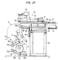
- the discharge station 6 shown in Figs. 26 thru 27 generally includes a discharge mechanism 48, a discharge lifter 49, a clearing mechanism 50 and an upstanding mechanism 51.
- the discharge mechanism 48 is adapted to take out the culturing containers from the culturing rack 5.
- the discharge lifter 49 is adapted to mount thereon the culturing containers discharged from the rack 5 by the discharge mechanism 48, and to displace them in vertical direction.
- the clearing mechanism 50 is disposed on the discharge lifter 49 for clearing the culturing containers mounted on the discharge lifter 49.
- the upstanding mechanism 51 is adapted to receive containers discharged out of the discharge lifter 49 and to permit the containers to be at their upstanding positions.
- the discharge mechanism 48 includes an elevation member 52 vertically movable, a power cylinder 53 mounted on the elevation member 52 and a push rod 55 extending in the axial direction of the lying containers into the rack 5 and movable in axial direction thereof along a guide rod 54.
- the discharge mechanism 48 is disposed at a position opposite the discharge lifter 49 with respect to the rack 5.
- the cylinder 53 is actuated to move the push rod 55 frontwardly (toward the culturing rack 5), so that a plate the push rod 55 abuts the front end of the front containers in the rack 5.
- the containers are moved toward the discharge lifter 49, and are placed on the upper surface thereof.
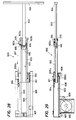
- a telescopic discharge mechanism 600 shown in Figs. 28 and 29 is used.
- the telescopic mechanism 600 has double stage telescopic movement to minimize axial length upon retraction thereof, so that the mechanism 600 can be installed within a rack supporting apparatus S having small transversal width. Therefore, resultant apparatus can provide a compact overall size.
- the telescopic discharge mechanism 600 includes a main frame 601 in which a slide flame 602 is disposed slidably extendable and retractable with respect thereto. Further, within the slide flame 602, a push rod 603 is disposed slidably extendable and retractable with respect thereto. A free end of the push rod 603 is fixed with a pushing plate 604 by which culturing containers 1 are pushed toward the discharge lifter 49.
- the main frame 601 is provided with rails 605 605 at a bottom surface thereof, and a lower surface of the slide frame 602 is in slide contact with the rails.
- Pulleys 607 and 608 are provided at both longitudinal ends of the main frame 601, and a drive motor 610 is disposed below the main frame 601.
- a chain 606 is mounted between the pulleys 607 and 608 and is driven by the motor 610.
- One longitudinal base end (left side end in Fig. 28, or rear end) 602a of the slide frame 602 is integrally provided with a protrusion 602b which is coupled to the chain 606.
- the drive chain 606 is subjected to tension control by a tension pulley609.
- a pulley 611 is provided at the base end 602a of the slide frame 602, and the pulley 611 is engaged with a chain 612.
- One end of the chain 612 is fixedly secured to the front end of the main frame 601 by means of a fixing member 613 extending from one side surface of the frame 601, while another end of the chain 612 is fixedly secured to a fixing member 603b fixed to a rear base end 603a of the push rod 603.
- the chain 612 is normally urged toward the rear end of the main frame 601, i.e., leftwardly in Fig. 28.
- a pulley 615 is provided at the front end of the slide frame 602, and the pulley 615 is engaged with a chain 617.
- One end of the chain 617 is fixedly secured to a fixing member 614 extending from another side surface of the main frame 601, while another end of the chain 617 is fixedly secured to a fixing member 603c fixed to the rear base end 603a of the push rod 603.
- the chain 617 is normally urged toward the rear end of the main frame 601, i.e., leftwardly in Fig. 28.
- a pair of guide rollers 616, 616 are rotatably supported to the rear base end 603a of the push rod 603.
- the guide rollers 616 are in rolling contact with an internal surface of the slide frame 602, so that the push rod 603 is smoothly movable relative to the slide frame 602.
- the motor 610 is a reversible motor. If the reversible motor 610 is rotated in a counterclockwise direction in Fig. 29, The slide frame 602 is moved toward left because of the coupling engagement between the chain 606 and the protrusion 602b. By the leftward movement of the slide frame 602, the pulley 616 at the rear base end 603a is urged leftwardly, so that the pulley 615 is also moved leftwardly. Therefore, the the push rod 603 is retracted into the slide frame 602 in response to the leftward movement of the slide frame 602.
- the slide frame 602 is moved rightwardly in the Figure, so that the pulley 611 is moved rightwardly for relaxing the tension applied to the chain 612. Accordingly, the chain 617 drives the base rear end 603a of the push rod 603 rightwardly, so that the push rod extends out of the slide frame 602, whereby containers are pushed toward the discharge lifter.
- the discharge lifter 49 can be elevated at a position in alignment with the vertically elevated position of the elevation member 52. After the culturing containers 1 are moved from the culturing rack and mounted on the upper surface of the discharge lifter 49 by the operation of the discharge mechanism 48, the discharge lifter 49 is moved to its descent position. At the upper surface of the discharge lifter 49, there is provided transfer plates 56 movable toward and away from the rack 5 by a cylinder 57 for mounting the containers on recessed portion 56a (Figs. 30 and 31) when the containers are transferred from the culturing rack 5 to the discharge lifter 48.
- the recessed portion 56a has arcuate cross-section for preventing the container from its lateral displacement, and has a front end portion 56b having arcuate edge shape similar to the transferring plate of the infeed lifter 10, which arcuate edge shape can allow the culturing container 1 to be smoothly discharged out of the culturing rack 5 without any mechanical interference with the flange 45 of the roller 41.
- Each of the transferring plates 56 is positioned at an intermediate position between the neighbouring rollers 41 and 41 as shown in Fig. 23 similar to the transferring plates 18 of the infeed station 4. The transferring plates 56 extend into the inside of the culturing rack 5 without any interferance with the flanges 45 of the rollers 41.
- the rear end portion of the rear container 1 installed in the rack 5 is moved upwardly, since the container rear portion rides onto the inclination surface of the front end portion 56b of the transferring plate 56.
- the upward position is higher than the upper end position of the flange 45.
- a discharge stop member 58 at the rear side thereof to which the rear end of the rear container abuts for preventing the container from being dropped from the lifter 49, and a power cylinder 59 for vertically displaceing the stop member 58 for selectively release the stop function of the stop member 58 (see Figs. 32 and 33).
- the clearing mechanism 50 has a construction substantially the same as that of the push-out mechanism 11 of the infeed station 4 as shown in Figs. 27, 30, 31, 34 and 35, and includes a discharge slider 61, a nut 62, a ball screw 63, a pulley 64 a motor 65, a discharge feeder 66 and a cylinder 67.
- the discharge slider 61 is slidably disposed on a guide rail 60 fixed to an upper surface of the discharge lifter 49 and movable toward and away from the culturing rack 5.
- the nut 62 is integrally fixed to the discharge slider 61 and is threadingly engaged with the ball screw 63, so that the discharge slider 61 is movable by the rotation of the ball screw through the nut 62.
- the ball screw 63 has one end portion integrally provided with the pulley 64 which is driven by the rotation of the motor 65 through a belt.
- the discharge feeder 66 is positioned at front side of the discharge slider 61. The feeder 66 abuts the front end of the front culturing container 1 lying on the discharge lifter 49 and pushes the container toward the upstanding mechanism 51 for clearing the containers from the lifter 49.
- the cylinder 67 is provided for moving the feeder 66 in vertical direction.
- the front end of the front container 1 is supported by the discharge feeder 66, and therefore, the containers lying on the discharge lifter 49 is prevented from being axially displaced even during descending motion of the lifter 49, and further, the containers are moved toward a a plurality of receptacle bars 68 described later of the upstanding mechanism 51 by the rearward movement of the discharge feeder 66.
- the upstanding mechanism 51 includes a discharge arm 69, a cam link 70, a disc cam 73, a swing arm (clearing unit) 74 and a cam 77.
- the discharge arm 69 has, at its one end portion, a support plate 69a for abutting the bottoms of the containers 1 and for supporting the same, and the receptacle bars 68 each extending perpendicular to the support plate 69a and having triangular cross section for spacedly receiving containers as shown in Fig. 36.
- the receptacle bars 68 are positioned at the rear side of the discharge lifter 49.
- the discharge arm 69 has an intermediate portion rotatably supported, and another end portion (lower end portion) connected to the cam link 70 through a link member 71.
- the cam link 70 is provided with a first and second rod members 70a and 70b. Rear ends of the rod members 70a, 70b are rotatably provided about an identical rotation axis 70c. A front end of the first rod member 70a is rotatably connected to the another end portion of the discharge arm 69 through the link 71. A front end of the second rod member 70b is rotatably provided with a roller 72 with which the disc cam 73 is in camming contact.
- the swing arm 74 has first and second arm members 74a and 74b.
- One ends of the arm members 74a and 74b are assembled together and rotatable about an identical axis 74c.
- a free end of the first arm member 74a is fixed with a push member 75 extending toward a discharge conveyor 7, and a free end of the second arm member 74b is rotatably provided with a roller 76.
- the cam 77 is in surface contact with the roller 76 and are rotatable together with the rotation of the disc cam 73.
- the culturing container 1 is dropped onto the container receptacle bars 68 in its lying state as shown in Fig. 35.
- the discharge arm 69 is angularly rotated by 90 degrees in counterclockwise direction in Fig. 27 because of the rotation of the disc cam 73. Therefore, the culturing container 1 maintained in the receptacle bars 68 is directed in its upstanding orientation.
- the push member 75 moves toward the discharge conveyor 7 by the rotation of the discharge cam 77, so that the side peripheral surface of each upstanding container 1 is urged toward the conveyor 7.
- the bottom end of the container is slidingly moved and the container is rested on the conveyor 7 in its upstanding posture.
- Container discharge operation is conducted according to the following prosedures: After the culturing rack 5 is moved to a predetermined position which confronts the discharge station 6, the position of the rack 5 is acknowledged, and the rotation of the drive sprocket 36 is suspended. Then the elevation member 52 and the discharge lifter 49 are elevated to a position corresponding to desired stage of the rack 5, and the ascending movements of the member 52 and the lifter 49 are stopped.
- the transferring plate 56 is moved frontwardly, and the discharge stop member 58 is moved to its ascent position, while rotation of the motor 39 for rotating the rollers 41 is suspended.
- the transferring plate 56 is moved frontwardly, so that the transferring plate 56 is inserted into a space defined between the neghbouring rollers 41.
- the rear end portion of the rear container 1 is slidingly elevated to a position higher than that of the upper end of the flange 45 along the front slanting portion of the front portion 56b of the transferring plate 56.
- the frontward movement of the transferring plate 56 is stopped at a predetermined position.
- the front end of the front container may be urged frontwardly due to the frontward movement of the transferring plate 56.
- frontward displacement of the container can be obviated.
- the movement of the transferring plate 56 is stopped, and then the the push rod 55 of the discharge mechanism 48 is moved toward the rack 5 and abuts the front end of the front container 1 lying in the rack 5.
- the containers 1 slidingly move with respect to the inclined surface of the front end portion 56b of the transferring plate 56.
- the push rod 55 continuously pushes the containers until the rear end of the rear container 1 abuts the stop member 58 positioned rearwardly with respect to the push rod 55.
- the discharge feeder 66 is maintained at its ascent position so as not to prevent the containers from moving.
- the transfer plate 56 and push rod 55 are moved back to their original rest positions, and then, the discharge feeder 66 is moved to its descent position to support the front end of the front container 1 (Fig. 27).
- the container 1 is stationarily held by the discharge feeder 66, the stop member 58 and the transferring plate 56.
- Such stationary supporting manner is maintained during the descent movement of the elevation member 52 and the discharge lifter 49.
- the discharge stop member 58 is moved to its descent position for providing support-free state to the containers 1.
- the discharge slider 61 is moved toward the upstanding mechanism 51 after acknowledgement of the upper predetermined position of the supporting plate 68 for dropping the rear container thereon by its gravity as shown in Fig. 35.
- the front end of the rear container is loosely engaged with the rear end of the front container, and therefore, the rear container 1 is easily disengaged from the front container.
- the movement of the slider 61 is stopped at its intermediate position, and the discharge arm 69 is angularly rotated downwardly by 90 degrees, so that the container 1 is comming into its upstanding position on the support plate 69a.
- the push member 75 is extended through the receptacle bars 68 and pushes the side wall of the container 1 to discharge it onto the discharge conveyor 7 with maintaining upstanding position thereof.
- the discharge arm 69 is rotated upwardly by 90 degrees to restore its stand-by position, and the the discharge slider 61 is further moved from its intermediate position toward the upstanding mechanism 51, so that the front container is also dropped onto the receptacle bars 68 and is discharged to the conveyor 7.
- the convevor 7 Prior to the discharge of the front container 1 toward the convevor 7, the convevor 7 is driven to displace the provisionally carried rear container 1 for providing a mounting space for the front container 1.
- Fig. 37 shows an upstanding mechanism 700 according to another embodiment of this invention in the discharge station.
- the upstanding mechanism 700 includes a discharge arm 701 corresponding to the arm 69 shown in Fig. 26.
- the discharge arm 701 is swingable about a shaft 702, and a free end of the discharge arm 701 is provided with a supporting plate 703 and a receptacle bars 704.
- One end of a first link 705 is connected to the shaft 702, and another end thereof is rotatably connected to one end of a connecting rod 706.
- the connecting rod 706 has another end rotatably connected to one end of a second link 707 whose another end is rotatably connected to one end of a third link 708.
- Another end of the third link 708 is rotatably supported to a frame.
- the rotatable connecting portion between the second and third links 707 and 708 is provided with a cam follower 711 which is in surface contact with a cam surface of a cam member 722 rotatable about an
- the clearing mechanism 712 includes a plurality of clearing bars 713, a first swing arm 714 for supporting the clearing bars 713, and a second swing arm 715 connected to the first swing arm 714.
- the connecting portion between the first and second swing arms is rotatable about an axis of a shaft 716.
- a free end of the second arm 715 is rotatably provided with a cam follower 717 which is in surface contact with a cam surface of a cam member 718 rotatable about an axis of the shaft 710.
- the cam members 718 and 722 are coaxially rotatable about the identical axis of the shaft 710 to which a gear wheel g1 is integrally provided.
- the gear wheel g1 is in meshing engagement with a gear wheel g2 which is rotated by a motor 719.
- the discharge arm 701 of the upstanding mechanism 700 is rotatably movable between its horizontal and vertical positions because of the contact between the cam member 722 and the cam follower 711.
- the discharge arm 701 is at vertical position shown by a broken line in Fig. 37, the containers are transferred from the discharge lifter 49 into the upstanding mechanism 700.
- the clearing mechanism 712 is also operated in sequential timing relative to the operation of the upstanding mechanism 700. Therefore, upstanding containers 1 are moved into the discharge conveyor 7 by the clearing mechanism 712, when the discharge arm 701 is at its horizontal position shown by a solid line in Fig. 37.
- the infeed lifter 210 and the discharge lifter 211 are vertically movable by the acuations of the hydraulic motors etc. as described above.
- a base plate 205 horizontally extends from an uppermost surface of the vertical frame plate 204 shown in Fig. 4, so that the base plate 205 is positioned above the culturing rack 5, and the motor 206 for driving the infeed lifter 211 and the motor 207 for driving the discharge lifter 211 are mounted on the base plate 205 in such a manner that these motors are spaced away from each other in directions parallel with and parpendicular to the travelling direction of the racks 5.
- the infeed and discharge lifters 210 and 211 are vertically movable by these motors 206 and 207 through power transmission mechanisms 208 and 209, respectively.
- a sterilized chamber 800 is provided, and the discharge conveyor 7 enters the chamber 800.
- a cap removing unit 804 for removing a cap 1a of the roller botlle 1
- the first liquid sucking and filling unit 805 includes a first liquid sucking portion 806a and a first liquid filling portion 807a, and is driven by a positive-displacement pump as a drive source such as reciprocating piston-cylinder, rotary-vane, gear or lobe mechanism.
- a transferring convevor 816 is disposed at a position adjacent to a distal end of the discharge conveyor 7 and is directed perpendicular thereto. Further, a bottle rolling unit 817 is juxtaposedly installed along the transferring conveyor 816 so as to fall down the upstanding bottles and provide rolling motion to the same.
- tiltable plates 818a and 818b are provided at both inlet and outlet portions thereof. The tiltable plates are swingable between their vertical and horizontal positions for falling down and upstanding the roller bottles 1.
- a slant plate 819 is provided which is gradually inclined downwardly toward the travelling direction of the transferring conveyor 816 so as to permit the roller bottles fallen down to be rollingly displaced.
- the tiltable plate 818a receives the roller bottle 1 which is displaced from the transferring conveyor 816 by a pusher (not shown), and is gradually inclined toward its horizontal direction for lying the roller bottle 1. And the tiltable plate 818b is adapted to hold the bottle 1 rolling down along the slant plate 819 and to render the bottle to be moved to its upstanding position and be displaced onto the transferring conveyor 816.
- An outlet end of the transferring conveyor 816 is connected, through a guide plate 825, to an infeed conveyor 826 extending perpendicular to the transferring conveyor 816.
- the infeed conveyor 825 is provided with a second liquid sucking and filling unit 805b having the construction the same as the first liquid sucking and filling unit 805a described above.
- the second liquid sucking and filling unit 805b includes a second liquid sucking portion 806b and a second liquid filling portion 807b, and a positive-displacement pump is provided for driving the second unit 805b.
- a cap fitting unit 827 for providing the cap to the roller botlle 1 is disposed.
- the roller bottle 1 is selectively subjected to various treatment such as injection of the culture medium, cleaning, and sucking of the culture medium when the bottle 1 passes through the above mentioned units.
- a bypass conveyor 78 is disposed at a position outside of the sterilized chamber 800.
- the bypass conveyor 78 extends in a direction perpendicular to the infeed and discharge conveyors 3 and 7.
- Guide plates 820 and 821 are disposed at both distal ends of the bypass conveyor 78.
- the guide plates 820 and 821 are selectively operated so as to displace the roller bottle 1 carried by the discharge conveyor 7 directly toward the infeed conveyor 3 obviating the insertion of the roller bottle 1 into the sterilized chamber 8.
- new roller bottles 1 are juxtaposed on the discharge conveyor 7, and the conveyor 7 is driven. Caps of the roller bottles 1 on the conveyor 7 are removed by the opener 804, and the first cultured liquid is filled into the bottles by the first filling portion 807a. Thereafter, the roller bottles 1 are transferred, through the transferring conveyor 816, to the infeed conveyor 3 at which the roller bottles 1 are subjected to cell inoculation by the second filling portion 807a. Thereafter, the bottles are capped with caps at the cap fitting unit 827. Thus processed bottles 1 are transferred to the infeed station 4.
- the roller bottles are successively accommodated into the culturing racks.
- two racks are completely filled with the bottles 1, succeeding two racks are brought to a position in front of the infeed station 4 for accomodating the bottles thereinto.
- Each of the roller bottles 1 is rotated about its axis by the rollers 41 within the rack for culturing for a predetermined period of time.
- the racks are successively moved to a position in front of the discharge station 6, and bottles are taken out of the rack 5 and are positioned on the discharge conveyor 7.
- the caps of the roller bottles 1 transferred by the discharge conveyor 7 into the sterilized chamber 800 are removed by the cap removing unit 804, and liquid in the bottles 1 are removed by the first suction unit 806a.
- the bottles 1 are subjected to rinsing by injecting cleaning liquid into the bottles 1 by the first liquid filling portion 807a. Thereafter, the roller bottles 1 rollingly travel along the rolling unit 817 because of their gravity for rinsing the interior of the roller bottles.
- the rinsing liquid is removed by the second suction portion 806b and a new culture medium (second culture liquid) is filled by the second filling portion 807b.
- the bottles 1 are capped with the caps at the second cap fitting unit 827.
- roller bottles 1 are transferred to the infeed station 4 for the next culturing operation.
- Such roller bottles 1 are accommodated in the rack 5 by the infeed station 4, and the roller bottles 1 are recovered on the discharge conveyor 7 after completion of the predetermined cell culturing for a predetermined period of time.
- the bottles 1 transferred into the sterilized chamber 800 are subjected to cap removing operation at the cap removing unit 804, and thereafter, the bottles 1 merely pass through the first liquid suction and filling portion 805a.
- the internal liquid is removed and new liquid culture medium (a third culture liquid) is filled in the bottle.
- the bottles 1 are capped with the caps at the cap fitting unit 827.
- treated bottles 1 are transferred to the infeed station 4, and are subjected to culturing for a predetermined period of time in the rack 5. After the culturing, the bottles are removed from the rack 5 and are positioned on the discharge conveyor 7.
- the bottles entered into the sterilized chamber 800 is subjected to cap removing by the cap removing 804, and then, a paste which serves as a forming liquid is collected by the first suction portion 806a.
- the bottles are then capped with the caps by the cap fitting unit 827. Therefore, overall steps are completed.
- roller bottles containing fresh culture medium and cells are supplied into the rotary rack 5 of the rack supporting apparatus S.
- Fig. 1 totally thirty-two culturing racks 5 are arranged in the loop path, and all racks 5 are subjected to accommodation of the roller bottles.
- a step 1000 acknowledged are (a) a position of the infeed pusher 12 as shown in Fig. 8, (b) position of the chain 17 as shown in Fig. 8, (c)rest position (lowermost descent position) of the infeed lifter 10 as shown in Fig. 8, and (d) leftmost position of the infeed slider 23 as shown in Fig. 8, and then, infeed conveyor 2 is operated in step 1001.
- step 1002 when the sensor 301 detects five roller bottles, the stop unit 302 is operated, and the second stop unit 304 is operated upon detection of tenth roller bottle.
- step 1003 the infeed conveyor 3 is stopped, and infeed stop member 20 is moved to its ascent position simultaneously with the pushing operation of the infeed pusher 12 in steps 1004 and 1005.
- step 1006 the chain 17 is driven in a normal direction to transfer, along the arcuate guide member 16a, ten roller bottles arranged side by side toward the rear end of the guide member 16b of the infeed lifter 10.
- steps 1002 to 1003 are performed, so that the chain 17 is rotated by a single stroke to restore its original position, and operation according to the step 1005 is repeated.
- subsequent ten roller bottles are also transferred toward the rear end of the guide member 16b by another rotation of the chain 17 (step 1007).
- front ends of the subsequent ten roller bottles push the rear ends of the leading ten roller bottles already reached to the guide members 16b, and accordingly, the two roller bottles (front and rear bottles) are respectively mounted on each of the guide members 16b.
- the cylinder 29 is actuated to swing the infeed member 28 for positioning the bottles 1 at their initial position in step 1008.
- the motor 27 is energized to move the infeed slider 23 to its intermediate position where the front end of the front roller bottle abuts the stop member 20 protruding from the front end of the infeed lifter 10, and the motor 27 is deenergized in steps 1009 and 1010.
- the infeed lifter 10 is elevated to a position corresponding to uppermost stage position of the rack 5, and the upward movement of the lifter 10 is stopped at that position in steps 1011 and 1012.
- the infeed stop member 20 is moved to its descent position for relaxing the front end of the front roller bottle 1 in a step 1013, and at the same time, the transferring plates 18 is moved frontwardly in step 1014. Then, the infeed slider 23 stopped at the intermediate position is again moved frontwardly, so that bottles are inserted into the uppermost stages of the two racks 5 juxtaposed with each other in step 1015. The movement of the slider 23 is stopped upon completion of the insertion in step 1016. Then, the transferring plate 18 is moved toward its original position in step 1017, and further, the infeed slider 23 is moved to its original position in step 1018 concurrent with the movement of the infeed member 28 toward its original position by the actuation of the cylinder 29 in step 1019.
- the infeed lifter 10 is moved to its descent position in step 1020 to thus terminate the bottle infeed opreration with respect to the single stage of the rack 5.
- the above described operations are repeatedly carried out for the remaining stages of the rack in step 1021. If the first two racks 5 are completely filled with the roller bottles 1, subsequent two racks 5 are moved to the bottle infeeding positions, and the above-described infeed operations are again performed. After each of the racks is completely filled with the roller bottles 1, culturing operation is initiated. That is, the drive motor 39 in each of the racks 5 is energized in order to rotate the rollers 41 for rotating the roller bottles 1 supported thereon.
- roller bottles 1 in the culturing rack 5 are discharged therefrom.
- Such bottle discharge is required for the exchange of culture medium contained in the bottle with a fresh culture medium, or for collecting targetting material formed in the bottle by the cultivation therefrom.
- step 1200 acknowledged are (a) the suspended positions of the two racks 5 at their discharge positions, (b) restoration of the transferring plate 56 to its original position, (c) original position (frontward position) of the discharge slider 61, (d) origianl position of the push rod 55 of the discharge mechanism 48, and (e) bottle receiving position of the discharge arm 69 of the upstanding mechanism 51 as shown in Fig. 27.
- the discharge lifter 49 is elevated and is stopped at a position corresponding to the uppermost stage of the two racks 5 in steps 1201 and 1202.
- the transferring plates 56 extend into the racks 5 in step 1203, the discharge stop member 58 is moved to its ascent position in step 1204, and the driving of the rollers 41 are suspended in step 1205.
- the push rod 55 is moved toward the culturing racks 5 in step 1206 for pushing the roller bottles 1 from the racks 5 onto the discharge lifter 49, and thereafter, the tarnsferring plates 56 are restored to their original positions, while the push rod 55 is retracted in steps 1207 and 1208.
- the cylinder 67 is operated to swing the discharge feeder 66, so that the front end of the front roller bottle 1 is held by the feeder 66 in step 1209, and the discharge lifter 49 is moved to its descent position and is stopped thereat in steps 1210 and 1211.
- the discharge stop member 58 is moved to its descent position in step 1212 to allow the bottles to pass thereover, and the discharge slider 61 is moved to its intermediate position and is stopped in steps 1213 and 1214.
- the receptacle bars 68 of the upstanding mechanism 51 are at their bottle receiving positions, so that ten bottles arranged side by side are dropped onto the receptacle bars 68.
- the discharge arm 69 is moved in counterclockwise direction in Fig. 27 in step 1215, and the swinging movement of the discharge arm 69 is stopped at horizontal orientation thereof.
- the swing arm 74 is operated to displace the bottles on the support plate 69a toward the discharge conveyor 7 in step 1216.
- the discharge arm 69 is reversely rotated in the clockwise direction in Fig. 27, and the discharge conveyor 7 is driven by a certain length and is stopped, so that the subsequent ten bottles can be shifted onto the conveyor 7 in steps 1217 and 1218.
- the discharge slider 61 is moved from its intermediate position toward the upstanding mechanism 51 and is stopped in step 1219.
- the receptacle bars 68 of the discharge arm 69 receive thereon the front ten roller bottles 1, and the discharge arm 69 is rotated in counterclockwise direction in Fig. 27 to its horizontal orientation in step 1220, and then the swing arm 74 is operated to displace the ten roller bottles toward the discharge conveyor 7 in step 1221.
- the discharge arm 69 and the discharge slider 69 are moved back to its original position for the next bottle receiving operation.
- Such sequential operations are repeatedly carried out in accordance with every stage of the culturing rack 5, and therefore, all roller bottles 1 are discharged from all stages of the rack 5. After the discharges of the bottles from the two racks are completed, subsequent two racks are moved to the bottle discharge positions, and above-described discharge operations are repeatedly carried out.
- exchanged is culture medium in the roller bottle which is subjected to culturing for a predetermined period of time. That is, after the cultivation for the predetermined period, nutritive substance in the culture medium is decreased, while metabolic substance such as ammonia and lactic acid etc. is increased in the culture medium. Therefore, metabolic substance containing medium is required to be replaced by the fresh culture medium.
- the discharged roller bottles 1 are subjected to treatment at the handling station 2, and are again returned into the culturing rack 5.
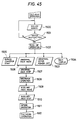
- roller bottle discharge operations with respect to the first two racks are conducted in step 1300.
- the racks are moved by a length equal to the two racks in running direction thereof, so that subsequent two racks are brought into the bottle discharge positions in step 1301 for the bottle discharge operations.
- the roller bottles discharged from the racks 5 are transferred into the handling station 2 for the above-described exchanging operation, and are transferred to the infeed station 4 through the infeed conveyor 3.
- roller bottles treated at the handling station 2 are supplied into the two racks 5 in step 1302.
- the bottle discharge operations are continuously performed in accordance with step 1303. Therefore, roller bottles fed into the racks are subjected to the culturing operation.
- the inspection operation is required to prevent roller bottles from infectious contamination with microorganism, when one of the roller bottles is contaminated with microorganism by provisionally inspecting color change of the roller bottles.
- a personnel is stationed on a predetermined inspecting spot 47 shown in Fig. 1, and visual observation to the color change of the roller bottles is conducted by automatically moving and temporalily stopping the racks in front of the personnel in steps 1400, 1401 and 1402.
- a rack number and a stage number which houses and installs the abnormal bottle is inputted through a numerical key of an operation key board in step 1403.
- the bottles at the stored stage of the stored rack are all discharged into the discharge conveyor 7 when the rack stored through the key board is brought to the bottle discharge position in step 1404.
- normal bottles are also inclusive, and therefore, the abnormal bottle is selected in step 1405, and the bypass conveyor 78 is operated in step 1406 to carry remaining normal bottles to the infeed conveyor 3.
- the specific rack is moved to the bottle infeed position, so that the normal bottles carried by the infeed conveyor 3 are again supplied into the rack for continuing culturing operation in steps 1407 and 1408.
- bottle infeed and discharge operations are made with respect to the two confronting racks.
- bottle infeed and discharge can be made with respect to one single rack.
- total travel lengths of the infeed conveyor 3, the bypass conveyor 78 and the discharge conveyor 7 should be longer than the length given by the sum of outer diameters of the roller bottles which are discharged from the abnormal rack so as to afford to receive the discharged roller bottles upstandingly arranged side by side on these conveyors.
- at least one auxiliary rack is supplementally disposed on the rack supporting apparatus S.
- the numbers of the racks can be changeable by changing the position of the drive sprocket 36 shown in Fig. 2.
- step 1500 the drive motor 38 in the culturing rack 5 is operated in step 1500. If the motor 38 becomes inoperable condition shown in step 1501, back-up operation is initiated as shown in step 1502. Electrical power supply to the rack housing the abnormal motor is shut-off in step 1503, and the rack number housing the abnormal motor is displayed in step 1504.
- the bypass conveyor 78 is operated in step 1505, so that the abnormal rack is displaced to the bottle discharge position and is stopped thereat in steps 1506 and 1507.
- step 1508 At the bottle discharge position, all roller bottles accommodated in the abnormal rack are discharged therefrom in step 1508, and the empty auxiliary rack is shifted to the bottle infeed position and is stopped thereat in steps 1509 and 1510.
- automatically inserted into the culturing racks are the culturing containers (roller bottles) which are subjected to automatic filling of the culture medium and cells at the handling station, and the cells cultured in the containers at the culturing racks are automatically discharged therefrom and the containers are automatically returned back to the handling station. Therefore, completely automatic filling of the cell and the culture medium, culturing, and exchange of the culture medium are attainable.
- the culturing racks are displaceable on the loop track, and therefore, such movable arrangement can facilitate inspection to the culturing containers in the racks. Moreover, even if there is abnormality in one or another one of the culturing container during culturing, abnormality is promptly detected, and the containers in the abnormal rack are replaced easily into other normally operable culturing rack for continuing the cultivation because of the back-up function of this invention. Further, the numbers of the culturing racks are changeable and the rotary loop length is also changeable in accordance with the numbers of the racks. Thus, cell cultivation capacity is also controllable in the present invention.
- the semi-automatic culturing system 900 is provided with a culturing chamber 901.
- a plurality of handling windows 902 At right side wall of the chamber 901 in the Figure, there are provided a plurality of handling windows 902, and a door 903 is provided, so that the operator can have access to the culturing chamber 901.
- the above-described rotary type rack supporting apparatus S are juxtaposedly installed in the culturing chamber 901.
- culturing container handling apparatus 905 is disposed at a position confronting the side wall at which the windows 902 are provided.
- conducted are supply of the culture medium, cell inoculation, and rinsing with respect to the culturing containers.
- a working space 907 is provided between the culturing chamber 901 and the handling apparatus 905 for the purpose of operators' labour.
- discharge and infeed conveyors 906a and 906b of a conveying means 906 are installed.
- a cap removing unit 903 for removing the caps of the roller bottles 1, a first suction portion 909 for sucking liquid in the roller bottles, and a first filling portion 910 to inject culture medium into the bottles for the inoculation of cells.
- a transferring conveyor 912 is installed between an outlet end of the discharge conveyor 906a and an inlet end of the infeed conveyor 906b.
- a bottle rolling unit 911 is disposed for rollingly move the roller bottles thereon toward the inlet end of the infeed conveyor 906b.
- a second suction portion 913 for sucking liquid in the bottles and a second filling portion 914 for injecting culturing liquid into the bottles.
- a cap fitting unit 915 is disposed for providing caps onto the bottles at a downstream side of the second filling portion 914.
- Operators P stand on places adjacent to the handling windows 902 and manually perform bottle infeed and discharge operations between the chamber 901 and the handling apparatus 905.
- a control box 916 is provided for each of the operators. The operator manipulate the control box 916 for driving the conveyors and for operating the actuation or deenergization of the rack supporting apparatus S.
- a rotary fan f is disposed above each of the operators p for blowing purified air toward the operators (Fig. 47).
Landscapes
- Health & Medical Sciences (AREA)
- Wood Science & Technology (AREA)
- Life Sciences & Earth Sciences (AREA)
- Engineering & Computer Science (AREA)
- Bioinformatics & Cheminformatics (AREA)
- Organic Chemistry (AREA)
- Chemical & Material Sciences (AREA)
- Zoology (AREA)
- Biomedical Technology (AREA)
- Sustainable Development (AREA)
- Microbiology (AREA)
- Biochemistry (AREA)
- General Engineering & Computer Science (AREA)
- General Health & Medical Sciences (AREA)
- Genetics & Genomics (AREA)
- Biotechnology (AREA)
- Clinical Laboratory Science (AREA)
- Apparatus Associated With Microorganisms And Enzymes (AREA)
Description
- The present invention relates to a cell culturing apparatus and call culturing method for culturing zooblast or animal cell, microorganizm and fungus, and plant structural piece.
- Generally, for the above cell cultivations, culture medium is supplied to a culturing container such as a roller bottle and a tray etc., and cell is inoculated thereon. Thereafter, such culturing container is placed in a culturing rack at a constant temperature for a predetermined period of time for promoting the cell cultivation. Upon completion of the cultivation, the culturing container is discharged from the culturing rack, for collecting cultured cell and its metabolic substance.
- A system for automatically handling the culturing containers has been proposed in commonly assigned US application serial No: 099, 341 filed on September 21,1987 or European Patent Application No: 87113905.1 filed September 23,1987 (publication No: EP-A-026159). In this handling system, filling and exchange of culture medium and cell relative to the culturing containers are automatically performed.
- In this proposal, automatic filling of the cell and culture medium into the culturing containers and automatic discharge of these from the containers are attainable, and therefore, container handling efficiency can be improved. However, after these container handling operation, it is necessary to transfer the processed containers into the culturing racks, and prior to the container handling operation it is necessary to transfer the containers after culturing from the racks to the handling system. For this, personnel manually inserts the containers into the racks for culturing, and manually discharge the container from the rack after culturing and manually inserts the same into the handling system.
- In this case, since an interior space of culturing chamber has a temperature about 37°C which temperature is higher than bodily temperature, such manual labours may cause pain to the personnel. As a result, such manual operations may degrade resultant container handling and transferring efficiency, and overall processes may become costly. Further, there is a fear for the personnel to undergo contamination by various bacilli if he works in the culturing chamber for a long time. Therefore, long demand has been made for automatically conducting entire processing with preventing the personnel from entering the culturing chamber.
- It is therefore an object of the present invention to overcome the above-described drawbacks and disadvantages and to provide improved cell culturing apparatus and cell culturing method.
- Another object of this invention is to provide such apparatus and method capable of performing efficient processing to culturing containers while preventing a personnel from contamination with bacille.
- According to the invention, there is provided a cell culturing apparatus which uses culturing containers containing therein cells and culture medium for cell culturing, characterised by:
a rack supporting apparatus comprising a loop tracking means and a plurality of culturing racks each connected one after another in series and adapted to travel on said loop tracking means, each of said racks accommodating therein said culturing containers for cell culturing;
an infeed station disposed at a position alongside said loop tracking means for automatically supplying said culturing containers into said culturing racks, said infeed station comprising an infeed lifter which is vertically movable for temporarily mounting thereon said culturing containers in order to supply the culturing containers into said culturing racks, a posture changing mechanism comprising arcuate guide members having a lower end positioned in the vicinity of said infeed conveyor and an upper end directed toward said infeed lifter, an infeed pusher for pushing predetermined numbers of said culturing containers carried on said infeed conveyor toward said guide members, means for moving said containers along said arcuate guide members and turning the containers from an upstanding posture to a horizontal posture; and
a discharge station disposed at a position alongside said loop tracking means for automatically discharging said culturing containers which have been subject to culturing from said culturing racks, said discharge station comprising a discharge lifter which is vertically movable for temporarily mounting thereon said culturing containers in order to discharge the culturing containers from said culturing rack and an upstanding mechanism disposed adjacent said discharge lifter for, after travel of said containers through said discharge lifter, upstanding said culturing containers which have been lying in said horizontal disposition in said culturing racks. - The posture changing mechanism may comprise arcuate guide members having a lower end positioned in the vicinity of said infeed conveyor and an upper end directed toward said infeed lifter, a chain disposed along said arcuate guide members, said chain integrally providing a support member, and an infeed pusher for pushing predetermined numbers of said culturing containers carried on said infeed conveyor toward said guide members, said support member carrying said containers being pushed by said infeed pusher and moving the same along said guide members, gradually inclining said containers toward a horizontal posture.
- Alternatively the posture changing mechanism may comprise arcuate guide members having lower end positioned in the vicinity of said infeed conveyor and an upper end directed toward said infeed lifter, an infeed pusher for pushing predetermined numbers of said culturing containers carried on said infeed conveyor toward said guide members, a container infeed unit adapted to move said culturing containers along said arcuate guide members causing said culturing containers to fall from their upstanding posture to a horizontal posture, said container infeeding unit comprising; a supporting plate positioned outside said arcuate guide members for supporting the bases of said culturing containers; support arms supporting said supporting plate and swingably movable between their horizontal and vertical postures aid containers supported on said supporting plate being gradually inclined toward a horizontal posture during their travel on said guide members by an upward swinging movement of said support arms.
- These and other objects of this invention will become more apparent from the detailed description of particular embodiments with reference to accompanying drawings.
- In the accompanying drawings;
- Fig 1 is a schematic plan view showing a cell culturing apparatus according to one embodiment of this invention.
- Fig 2 is a schematic plan view of the cell culturing apparatus particularly showing container infeed and discharge stations according to one embodiment of this invention;
- Fig. 3 is a side elevational view showing a rack supporting apparatus of this invention;
- Fig. 4 is a front elevational view showing the rack supporting apparatus shown in Fig. 3;
- Fig. 5 is a plan view showing a drive means for driving the culturing racks;
- Fig. 6 is an illustration showing the relationship between the culturing racks and chains fixedly secured thereto;
- Fig. 7 is a side elevational view of the infeed station; and, Fig. 8 is an enlarged side elevational view showing the infeed station;
- Fig. 9 is a front elevational view showing an infeed lifter;
- Fig. 10 is a side view showing a push-drive mechanism mounted on the infeed lifter;
- Fig. 11 is a side view showing transferring plates disposed on the infeed lifter;
- Fig. 12 shows an arrangement of guide members;
- Fig. 13 is a top view showing arrangement of culturing containers upstandingly aligned one after another at the infeed station;
- Fig. 14 is a side view of the culturing container partially cut away;
- Fig. 15 is a front elevational view showing an infeed stop member;
- Fig. 16 is an explanatory illustration showing a transfer of the culturing container from the infeed lifter to the rack;
- Fig. 17 is an explanatory illustration as viewed from a front side of the container in its transferring state shown in Fig. 16;
- Fig. 18 is a side view showing an infeed station according to a modified embodiment of this invention:
- Fig. 19 is a front elevational view showing the culturing rack; and, Fig. 20 is a side elevational view of the rack shown in Fig. 19;
- Fig. 21 is a front elevational view particularly showing a mechanism for driving rollers in the rack; and, Fig. 22 is a side elevational view of the rack and the roller driving mechanism those shown in Fig.21;
- Fig. 23 is a front elevational view showing the culturing rack in which a power transmission mechanism of the roller driving mechanism is delineated;
- Fig. 24 is a front elevational view showing a mechanism for driving rollers in the rack according to a modified embodiment of this invention;
- Fig. 25 is a side elevational view showing the roller driving mechanism shown in Fig. 24;
- Fig. 26 is a side elevational view showing the discharge station;
- Fig. 27 is an enlarged side elevational view showing a discharge lifter in the discharge station;
- Fig. 28 is a plan view showing a telescopic discharge mechanism; and, Fig. 29 is a side view of the telescopic discharge mechanism shown in Fig. 28;
- Fig. 30 is a front elevational view showing a discharge lifter;
- Fig. 31 is a side view showing a driving unit of a clearing mechanism mounted on the discharge lifter;
- Fig. 32 is a side view showing transferring plates disposed on the discharge lifter;
- Fig. 33 is a front view showing a stop member fixed to the discharge lifter;
- Fig. 34 is an explanatory illustration showing a transfer of the culturing container from the culturing rack to the discharge lifter;
- Fig. 35 is an explanatory illustration showing a transfer of the culturing container from the discharge lifter to an upstanding mechanism;
- Fig. 36 is an illustration showing a front end part of the upstanding mechanism shown in Fig. 27;
- Fig. 37 is a side elevational view showing an upstanding mechanism according to a modified embodiment of this invention;
- Fig. 38 is an elevational view as viewed from running direction of the racks and showing infeed and discharge stations according to a modified embodiment of this invention;
- Fig. 39 is a plan view showing a container handling station;
- Fig. 40 is a operational diagram in the container handling station;
- Figs. 41 through 45 are flow-charts showing infeed operation mode, discharge operation mode, simulteneous infeed and discharge operation mode, inspection operation mode, and back-up operation mode, respectively;
- Fig. 46 is a plan view showing a cell culturing apparatus according to another embodiment of this invention; and,
- Fig. 47 is a partial cross-sectional view taken from Fig. 46.
- One embodiment according to this invention will now be described with reference to accompanying drawings.
- A cell culturing apparatus according to the embodiment shown in Figs. 1 thru 2 is adapted to perform cell culturing and exchange with respect to rotary cylinder type cell culturing containers (roller bottles) 1 in which culture medium and cells are contained. The cell culturing apparatus generally includes a
handling station 2, aninfeed station 4, a rack supporting apparatus S including a rotarytype culturing racks 5, and adischarge station 6. In the handling station, filling of culture medium into the roller bottles, cell inoculation, and rinsing of the roller bottles are performed. The roller bottles containing therein the cells and culture medium are automatically supplied from thehandling station 2 to theinfeed station 4 by aninfeed conveyor 3, and theculturing containers 1 are transferred from the infeed station to therotary culturing racks 5 which are movable on a loop path of the rack supporting apparatus S. During the travel of the racks, cell culturing is promoted in theroller bottles 1. Theculturing containers 1 are then automatically discharged from theculturing racks 5 to thedischarge station 2 and are transferred to thehandling station 2 by a dischargingconveyor 7. In thehandling station 2, the cultured cells are removed from thecontainers 1, and the bottles are subjected to insertion of new cells and cluture medium. - The rack supporting apparatus S connects a plurality of
racks 5 one after another in the loop tracking path. As shown in Fig. 4, abase frame 204 vertically extend at longitudinal ends of the loop path. andhexagonal sprokects base frame 204, aguide rail 202 is installed. Each of theracks 5 is provided with aroller 35 at its upper portion thereof whichroller 35 is engageable with theguide rail 202. Further, acontact rod 200 extends from each upper surface of theracks 5. Thecontact rod 200 is in contact with an electricalpower supply unit 206 extending from the upper portion of thevertical frame 204. As shown in Figs. 6 and 7, thepower supply unit 206 and thecontact rod 200 serve to supply electrical current to amotor 39 for rotatingrollers 41 which support the culturing containers and rotate the culturing containers about their axes in theculturing rack 5. Themotor 39 and therollers 41 will be described in detail later. Each of the culturing racks 5 has a lower surface provided with aroller 34 which runs on arail 32 installed on a floor. - As shown in Figs. 4 thru 6, elongated chain C is fixedly secured to a lower inside face of each of the
racks 5. Each of the chains C is connected together by a pin a. Each of the pins a is engageable with arecess 36a formed at a corner portion of thehexagonal sprocket 36. The elongated chain and therecess 36a of thesprocket 36 define a temporarily stational position of therack 5 as shown in Fig. 5 when one of theracks 5 is at a position completely confronting the one side of thesprocket 36. Thesprocket 36 is connected to a drive motor M through anendless chain 203. Upon rotation of the motor M, each of the culturing racks 5 is displaceable on aloop tracking rail 32. - During travel of the
culturing containers 1 from thehandling station 2 to theinfeed station 4, thecontainers 1 are maintained in upstanding posture on theinfeed conveyor 3 which extends out of thehandling station 2. Between thehandling station 2 and theinfeed station 4 and on the path of theconveyor 3, astar wheel 8 is disposed which has five recesses successively formed on the circumferential surface thereof so as to provide a predetermined distance by every five culturing containers and to simultaneously supply a group of the fiveculturing containers 1 into asingle rack 5. - Each of the rack stages can receive therein five
culturing containers 1 from theinfeed station 4, and twoculturing racks 5 confront the infeed station, so that tenculturing containers 1 can be simultaneously transferred into the culturing racks 5. - As shown in Figs. 7 and 8, the
infeed station 4 generally includes aposture changing mechanism 9, aninfeed lifter 10 and a push-out mechanism 11. The posture changing mechanism is adapted to fall down theupstanding containers 1. Theinfeed lifter 10 mounts thereon the two containers oriented in horizontal direction and axially alinged with each other, and moves the two containers in vertical direction. The push-out mechanism 11 is disposed on theinfeed lifter 10 and is adapted to push theculturing containers 1 toward the culturing racks 5. The push-out mechanism is vertically movable in accordance with the vertical movement of theinfeed lifter 10, while the collapsingmechanism 9 is not displacable in vertical direction. - The
posture changing mechanism 9 is disposed opposite theculturing racks 5 with respect to theinfeed conveyor 3, and includes aninfeed pusher 12, aswing arm 14, acam member 15,guide members 16a and achain 17. Theinfeed pusher 12 has alongitudinal center portion 12a rotatably supported so as to simultaneously fall down tenupstanding culturing containers 1 toward the culturing racks 5. Theswing arm 14 has oneend 14a connected to the end of theinfeed pusher 12 through a linkingrod 13, and anotherend 14b rotatably supported. The intermediate portion of theswing arm 14 is in contact with thecam member 15 so as to provide pivotal movement of theswing arm 14, to thereby swing theinfeed pusher 12 about thepivot portion 12a. Each of theguide members 16a has a quadrant shape and has triangular cross-section. Neighbouring two guide members define a triangular valley portion on which the culturing container is supported. Thechain 17 is driven along the arcuate path of theguide member 16a, and has a dog (support plate) 17a extending outwardly from thechain 17. - With the structure, upon rotation of the
cam member 15, theswing arm 14 in contact therewith is vertically pivotted about the anotherend 14b, so that thelower end 12b of theinfeed pusher 12 is pivotted through the connectingrod 13, about thecentral portion 12a, and is displaced toward theculturing container 1 upstandingly mounted on theinfeed conveyor 3. As a result, the side wall of theculturing containers 1 are pushed by thelower end 12b, and the containers are fallen down toward theguide members 16a. Each of the ten containers is fallen down and is supported by neighroubing twoguide members 16a as shown in Fig. 9. By the movement of thechain 17, thedog 17a supports bottom portion of each of thecontainers 1, and the containers change their angular orientation by 90 degrees from upstanding state to lying state during their travel along theguide members 16a. The lying containers are then supplied to an upper surface of theinfeed lifter 10. - As shown in Fig. 12, the
guide members 16a do not extend in parallelism from one another, but extend obliquely so that spaces defined between thenieghbouring guide members 16a are gradually increased toward theinfeed lifter 10. Since a plurality ofguide members 16b (Fig. 8) provided on theinfeed lifter 10 are disposed separately at a pitch, two neighbouringcontainers 1 are held separately from each other (Fig. 9). - Two axially aligned
culturing containers 1 in their lying states are mounted on theinfeed lifter 10 by the twice operations of theposition changing mechanism 9. Theinfeed lifter 10 can be vertically movable, so that thecontainers 1 mounted thereon are brought into a position coincident with the vertical position of the desired stage of therack 5. At the upwardly displaced position of thelifter 10, thecontainers 1 are transferred into therack 5. - In the
infeed lifter 10, disposed areguide members 16b for supporting thecontainers 1 with a space therebetween in lateral direction. Theguide members 16b are disposed in alignment with theguide members 16a, and, a transferringplate 18 is disposed at a space defined between the neighbouringguide members 16b. Each of the transferringplates 18 is provided with a recessedportion 18a having arcuate cross-section for avoiding displacement of the containers in radial direction thereof when theculturing container 1 is displaced from theinfeed lifter 10 to theculturing rack 5 by means of the push-out mechanism 11. The transferringplate 18 has atip end portion 18b provided with accute edge. The transferringplate 18 is movable toward theculturing racks 5 in longitudinal direction of theplate 18 by adrive cylinder 19. - The
infeed lifter 10 also includes ainfeed stop member 20 at a position in confrontation with the transferringplate 18 so as to restrain frontward displacement of theculturing containers 1. Further, a power cylinder 21 (Fig. 15) is provided to vertically move theinfeed stop member 20 so as to selectively provide free movement of thecontainer 1. - The push-
out mechanism 11 is shown in Figs. 8throu 10. The push-out mechanism 11 includes aninfeed slider 23, anut 24, aball screw 25, apulley 26, amotor 27, aninfeed member 28, and apower cylinder 29. Theinfeed slider 23 is slidingly movable toward the culturing racks 5 on aguide rail 22 installed on the upper surface of theinfeed lifter 10. Thenut 24 is integrally provided to theinfeed slider 23, and is threadingly engaged with theball screw 25. The ball screw 25 has one end portion provided with thepulley 26 which is rotatable by themotor 27 through an endless belt. Theinfeed member 28 is positioned integraly with and in front of theinfeed slider 23 and is adapted to push the bottom of therear culturing container 1 of the axially aligned two containers. Thecylinder 29 is adapted to move theinfeed member 28 in vertical direction. Here, the terms "front" and "rear" imply the closer and farrer positions with respect to theracks 5, respectively. - In the push-
out mechanism 11, upon rotation of themotor 27, theinfeed slider 23 is slidingly moved toward theculturing racks 5, so that the axially aligned two containers mounted on theinfeed lifter 10 are urged toward theracks 5 by theinfeed member 28. - Infeed operation of the
culturing containers 1 is carried out as follows:
Firstly, theinfeed convevor 3 and thestar wheel 8 are operated in order to supply two groups ofcontainers 1, each group having five containers, to a given position in front of theinfeed pusher 12 of theposture changing mechanism 9 and on theinfeed conveyor 3. After acknowledgement of these containers at the given position, the movement of theinfeed conveyor 3 is suspended. - This two container groups can also be prepared by an alternative operation shown in Fig. 13. That is, movement of the leading
container 1 is stopped by a stoppingplate 300, and five containers of the first group are detected by asensor 301. Upon this detection, a first stop unit 303 positioned adjacent thesensor 301 is operated to prevent the sixth container from its moving. Then, the succeeding four containers of the second group are detected by a sensor 303. When the another five containers of the second group are detected, asecond stop unit 304 is operated to prevent succeeding eleventh containers from moving. Therefore, two groups of the containers (totally ten containers) are aligned in front of theposture changing mechanism 9. - Then, the
cam member 15 is rotated to allow theinfeed pusher 12 to swing toward theguide members 16a, so that totally tencontainers 1 are fallen down onto theguide members 16a. - Thereafter, the
chain 17 is driven to a first direction to simultaneously slidably move the tencontainers 1 along theguide members 16a, so that theupstanding containers 1 are horizontally laying on theguide members 16b of theinfeed lifter 10. During travel of the containers each of the container bottoms is held by thedog 17a of thechain 17 and are moved toward the rear portion of theinfeed lifter 10 along theguide members 16a. Next, subsequent ten containers are introduced onto theguide members 16a and transferred onto theguide members 16b, during which each of the rear bottom ends of the already introduced ten containers are depressed by each of the front ends of the subsequent containers. As a result, two containers are axially aligned on the upper surface of theinfeed lifter 10. In this instance, acap 1a of therear container 1 is inserted into a recessedportion 1b of afront container 1, so that the two containers are integrally aligned on theguide member 16b as shown in Figs. 8 and 14. - The above operations are not interefered by the
feed member 28, since themember 28 is provisionally displaced at its ascent position. When two axially aligned containers are brought into the laying position, theinfeed member 28 is moved to its descent position by the extension of thecylinder 29, and upon acknowledgement of the descent position, theinfeed slider 23 is moved frontwardly toward the culturing racks 5. By the movement of theinfeed slider 23, theinfeed member 28 also moves to the same direction, so that the bottom portion of therear container 1 of the axially aligned two containers are pushed by theinfeed member 28. As a result, the two containers are moved toward the culturing racks 5. - In this instance, the
infeed stop member 20 positioned in front of the containers is provisionally displaced at its ascent position. Therefore, the front end of thefront container 1 is brought into abutment with thestop member 20 for positional adjustment. Concurrently, the movement of theinfeed slider 23 is terminated. - Each of the
containers 1 is supported by theguide members 16b, while the front end of thefront container 1 is in abutment with theinfeed stop member 20 and the rear end of therear container 1 is in abutment with thefeed member 28. Therefore, each of thecontainers 1 is held at stationary state in theinfeed lifter 10 without any axial and lateral displacement. Such non-shiftable containers are then moved to their ascent position by the upward movement of theinfeed lifter 10 by a vertical height coincident with that of the desired one of the stages of therack 5 into which the containers are to be inserted. - The upward movement of the
infeed lifter 10 is stopped, and thestop member 20 is moved to its descent position to release the fixing of the containers. At the same time, thetransfer plate 18 is moved frontwardly (toward the rack 5) by the actuation of thecylinder 19. In this case, themotor 39 for rotatingrollers 41 mentioned later in theculturing rack 5 is deenergized. - Referring in detail with the transferring
plates 18, as shown in Figs. 16 and 17, longitudinal axis of each of the transferringplates 18 extends along an intermediate space defined between adjacent tworollers rollers 41 is provided with twoflanges rear flange 45 does not prevent the transferringplate 18 from extending into the space and from moving between therollers rollers 41 and the plate18. - After the transferring
plate 18 exceeds theflange portion 45 and extends to a predetermined axial position of the space between therollers plate 18 is terminated. After acknowledgements of the advanced position of the transferringplate 18 and the descent position of theinfeed stop member 20, theinfeed feeder 22 is moved frontwardly (toward the culturing rack 5) to slidingly move the culturing containers with respect to theguide plates 16b, so that thecontainers 1 are brought into the positions of therollers 41. During the container travel from theguide plate 16b to theroller 41, the containers are supported by a recessedportion 18a of the transferringplate 18. Therefore, the containers can be smoothly transferred without their lateral displacement. Futher, the transferringplate 18 prevents the front end of the container from abutting against theflange 45 of theroller 41. - When the front end of the
front container 1 is brought into abutment with a rack stop member 46 (Fig. 22), and front end of theinfeed member 28 slightly exceeds theflange 45 of theroller 41, the position of thefeed member 28 is acknowledged, and the movement of theinfeed slider 23 is stopped, and thereafter, the transferringplate 18 is retracted to a direction opposite the rack. - During the retracted movement of the transferring
plate 18, the rear end of therear container 1 is in abutment with theinfeed member 28. Therefore, theinfeed member 28 prevents thecontainer 1 from axially moving rearwardly due to the retracting movement of the transferringplate 18. Instead, the containers are dropped onto therollers infeed member 28 is positioned frontwardly with respect to theflange 45, the rear end of therear container 1 is also droppingly positioned in front of theflange 45. As a result, thecontainers 1 are suppored by theflange 45 and thestop member 46 without any axial displacement. Such successive operations are performed without any trouble. - Then, the
infeed slider 23 is moved rearwardly (toward the posture changing mechanism), and theinfeed lifter 10 is moved to its origianl descent position for receiving new tencontainers 1 therein. Upon receipt of the containers, theinfeed lifter 10 is again moved upwardly to a predetermined new stage of therack 5 for inserting the containers to the selected stage of therack 5. Such infeed operations are repeatedly carried out, and accordingly, completed is the insertion of the culturing containers into theculturing racks 5 by means of theinfeed station 4. - An
infeed station 400 according to another embodiment of the present invention will be described with reference to Fig. 18. Theinfeed station 400 according to the another embodiment generally includes a posture changing mechanism 450 (corresponding to theposture changing mechanism 9 of the first embodiment), and a push-out mechanism 406 (corresponding to the push-out mechanism 11 of the first embodiment). Theposture changing mechanism 450 comprises aninfeed pusher 403, theguide member 401, acontainer supporting unit 404 and a container infeeding unit 402 (corresponding to the push-out mechanism 11 of the first embodiment). Theinfeed pusher 403 is adapted to push and fall down the containers on theinfeed conveyor 3 toward theguide members 401. Thecontainer infeeding unit 402 is adapted to supplycontainers 1 alongguide members 401 into theinfeed lifter 10 by reciprocally swingable rotation. Thecontainer supporting unit 404 is protrudable to the upper space of theconveyor 3 to support side walls of thecontainers 1 for preventing the containers from their falling down on theconveyor 3 during their state shown in Fig. 13, when ten containers are arranged in line with their upstanding positions on theconveyor 3. The push-outmechanism 406 is provided on theinfeed lifter 10, and is slidable on aslide surface 405. The push-outmechanism 406 pushes the containers lying on a horizontal portion of theguide member 401 and on theinfeed lifter 10 toward predetermined stage of theculturing rack 5 disposed at left margin of Fig. 18. - The
container infeeding unit 402 includes a supportingplate 407,support arms 407a, and acrank mechanism 408. The supportingplate 407 extends in a direction across theguide members 401 for supporting bottom portions of the containers at a position outside theguide members 401. Thesupport arms 407a are provided at the opposite ends of the supportingplate 407. Thesupport arms 407a are operably connected to the crankmechanism 408, so that thesupport arms 407a are reciprocally rotatable within angularly 90 degrees between horizontal position and vertical position as shown by solid line and two-dotted chain line. Thecrank mechanism 408 includes first, second and third links 409,410 and 411. Thethird link 411 is rotated together with the rotation of afirst gear wheel 412 which is in meshing engagement with asecond gear wheel 413 drivingly rotated by amotor 414 through a power transmission belt. - The
infeed pusher 403 includes apush rod member 415,first swing arms 416, asecond swing arm 417,and acylinder 418. Thepush rod member 415 extends in a transverse direction of the overall device and has a length larger than the outer diameters of the ten containers, so that upstanding containers can be pushed simultaneously by thepush rod member 415. Each of thefirst swing arms 416 has an upper end connected to the each end of thepush rod member 415, and a lower end connected to a lower end of thesecond swing arm 417. The upper end of thesecond swing arm 417 is connected to thecylinder 418. Upon extension and retraction of a rod of thecylinder 418, the first swing arm 416s are moved toward and away from the containers upstanding on theinfeed conveyor 3. - The
container supporting unit 404 is disposed between theinfeed pusher 403 and thecontainer infeeding unit 402. Thecontainer supporting unit 404 includes acontainer supporting plate 419 projecting in vertical direction and extending in transverse direction of the overall device, and acylinder 420 for moving the supportingplate 419 in vertical direction. Thecontainer supporting plate 419 is maintained at its ascent position, so that it extends in parallel with the rows of theguide members 401 until the upstandingly oriented ten containers on theinfeed conveyor 3 are aligned in line without offset of one or several ones of the containers. That is, as shown in Fig. 13, thecontainers 1 are subjected to force which restrains their travel on theinfeed convevor 3 by thestop plate 300. Therefore, thecontainers 1 on theconvevor 3 are urged to be in close contact with each other. In this state, if one of the containers is moved to the offset position, containers may be fallen down, and dropped from theconveyor 3. To avoid this, thecontainer supporting plate 419 is disposed. Thecontainer supporting plate 419 is retracted to its descent position when theinfeed pusher 403 urges the containers toward theguide members 401, so that the pushing operation by thepush rod member 415 is not disturbed by thecontainer supporting plate 419. - The push-out
mechanism 406 includes aslide frame 430 slidingly movable on aslide surface 405, aninfeed member 431 swingably provided on theslide frame 430 for abutting the bottom surface of thecontainer 1 and pushing the same, and apower cylinder 432 for moving theslide frame 430. Theinfeed member 431 is urged toward a direction for providing its vertical position (operable position) shown in a chain line by biasing force of aspring 433. When theinfeed member 431 is in a position shown by the solid line, theinfeed member 431 abuts astop member 434 protruding from the frame member of theinfeed lifter 10, so that theinfeed member 431 is maintained at its inoperable position where theinfeed member 431 does not prevent the containers running along theguide members 401 from their moving toward theculturing rack 5. That is, if the cylinder rod of thecylinder 432 is extended, theinfeed member 431 is moved away from thestop member 434. Therefore, theinfeed member 431 is rotated to a vertical operable position shown by the chain line by the biasing force of thespring 433. As a result, containers on the horizontal portion of theguide members 401 and on theinfeed lifter 10 are pushed toward therack 5 by the vertically orientedinfeed member 431. - The culturing racks 5 are assembled at internal space of
rack frame 31 of the rack supporting apparatus S as shown in Figs.19 thru 25. - In the interior of the
culturing rack 5, provided is arotation mechanism 37 for rotating theculturing container 1 about its axis and for promoting culturing of the cells contained therein. - The
rotation mechanism 37 includes amotor 39, adeceleration unit 38 connected to themotor 39, arotary shafts 40 rotatable by the rotation of themotor 39, androllers 41 rotatable by therotary shafts 40, therollers 41 mounting thereonculturing containers 1 for rotating the latter about their axes. - Six
rotary shafts 40 are arranged in line and in parallelism in horizontal direction as best shown in Fig. 16, whose number is equal to the number of therollers 41. One of therotary shafts 40 is integrally provided with apulley 42 which is rotatable by the rotation of themotor 39 through a belt 43a. By the rotation of the one of theshafts 40, otherrotary shafts 40 are rotated through apower transmission belt 43b. Further, a belt 44a is mounted between each of therotary shafts 40 and each of the upperadjacent rollers 41. Furthermore, abelt 44b is mounted between each of therollers 41 and each of the upper neighbouringrollers 41 as shown in Fig. 22. Therefore, the rotation of therotary shaft 40 is transmitted successively to the upperadjacent rollers 41 through thebelts 44a and 44b. - In the
rack 5, sixrollers 41 are arranged in line and in parallelism in horizontal direction, and ten stages of roller arrangements are provided in vertical direction. Therefore, totally 60rollers 41 are rotatably disposed in therack 5. Each one of theculturing containers 1 is supported by neibouring tworollers 41, and therefore, fivecontainers 1 are supported in the single stage. Thus supported containers are rotatable about their axes by the rotation of therollers 41. - Modification to the
culturing rack 5 is shown in Figs. 24 and 25. In the modified embodiment, theculturing rack 5 has a frame member F in which a plurality of supportingracks 531 are secured. On each of the supportingracks 531, there are provided a plurality ofrollers 41. Each of the culturing container 1 (roller bottle) is supported by the neighbouring tworollers 41. Aculturing motor 530 is installed at the lower portion of therack 5. The rotation of theculturing motor 530 is transmitted to therollers 41 of each stage through power tarnsmission means. The power transmission means includes elongated shafts 550,551,552,553 extending along a side wall of theframe F. Belts shafts shafts rightmost rollers 41 in the support racks 531 are connected to the elongated shafts 550,551,552 and 553 throughbelts motor 530 is connected to the lowermostelongated shaft 550 through apower transmission belt 555. The rollers on the identical supportingrack 531 are connected together to therightmost roller 41 bybelts rollers 41 are rotated about their axes in the same direction. Both axial end portions of theroller 41 are provided withflanges - The
discharge station 6 shown in Figs. 26 thru 27 generally includes adischarge mechanism 48, adischarge lifter 49, aclearing mechanism 50 and anupstanding mechanism 51. Thedischarge mechanism 48 is adapted to take out the culturing containers from theculturing rack 5. Thedischarge lifter 49 is adapted to mount thereon the culturing containers discharged from therack 5 by thedischarge mechanism 48, and to displace them in vertical direction. Theclearing mechanism 50 is disposed on thedischarge lifter 49 for clearing the culturing containers mounted on thedischarge lifter 49. Theupstanding mechanism 51 is adapted to receive containers discharged out of thedischarge lifter 49 and to permit the containers to be at their upstanding positions. - The
discharge mechanism 48 includes anelevation member 52 vertically movable, apower cylinder 53 mounted on theelevation member 52 and apush rod 55 extending in the axial direction of the lying containers into therack 5 and movable in axial direction thereof along aguide rod 54. Thedischarge mechanism 48 is disposed at a position opposite thedischarge lifter 49 with respect to therack 5. - After the
elevation member 52 is elevated to a predetermined position at which there is one of the stages of the rack storing the containers to be discharged, thecylinder 53 is actuated to move thepush rod 55 frontwardly (toward the culturing rack 5), so that a plate thepush rod 55 abuts the front end of the front containers in therack 5. When thepush rod 55 is further moved, the containers are moved toward thedischarge lifter 49, and are placed on the upper surface thereof. - Instead of the above-described
discharge mechanism 48, atelescopic discharge mechanism 600 shown in Figs. 28 and 29 is used. Thetelescopic mechanism 600 has double stage telescopic movement to minimize axial length upon retraction thereof, so that themechanism 600 can be installed within a rack supporting apparatus S having small transversal width. Therefore, resultant apparatus can provide a compact overall size. - In Figs. 28 and 29, the
telescopic discharge mechanism 600 includes amain frame 601 in which aslide flame 602 is disposed slidably extendable and retractable with respect thereto. Further, within theslide flame 602, apush rod 603 is disposed slidably extendable and retractable with respect thereto. A free end of thepush rod 603 is fixed with a pushingplate 604 by whichculturing containers 1 are pushed toward thedischarge lifter 49. Themain frame 601 is provided withrails 605 605 at a bottom surface thereof, and a lower surface of theslide frame 602 is in slide contact with the rails.Pulleys main frame 601, and adrive motor 610 is disposed below themain frame 601. Achain 606 is mounted between thepulleys motor 610. One longitudinal base end (left side end in Fig. 28, or rear end) 602a of theslide frame 602 is integrally provided with aprotrusion 602b which is coupled to thechain 606. Incidentally, thedrive chain 606 is subjected to tension control by a tension pulley609. - A
pulley 611 is provided at thebase end 602a of theslide frame 602, and thepulley 611 is engaged with achain 612. One end of thechain 612 is fixedly secured to the front end of themain frame 601 by means of a fixingmember 613 extending from one side surface of theframe 601, while another end of thechain 612 is fixedly secured to a fixingmember 603b fixed to arear base end 603a of thepush rod 603. With the structure, thechain 612 is normally urged toward the rear end of themain frame 601, i.e., leftwardly in Fig. 28. Firther, apulley 615 is provided at the front end of theslide frame 602, and thepulley 615 is engaged with achain 617. One end of thechain 617 is fixedly secured to a fixingmember 614 extending from another side surface of themain frame 601, while another end of thechain 617 is fixedly secured to a fixingmember 603c fixed to therear base end 603a of thepush rod 603. With the structure, thechain 617 is normally urged toward the rear end of themain frame 601, i.e., leftwardly in Fig. 28. A pair ofguide rollers rear base end 603a of thepush rod 603. Theguide rollers 616 are in rolling contact with an internal surface of theslide frame 602, so that thepush rod 603 is smoothly movable relative to theslide frame 602. - The
motor 610 is a reversible motor. If thereversible motor 610 is rotated in a counterclockwise direction in Fig. 29, Theslide frame 602 is moved toward left because of the coupling engagement between thechain 606 and theprotrusion 602b. By the leftward movement of theslide frame 602, thepulley 616 at therear base end 603a is urged leftwardly, so that thepulley 615 is also moved leftwardly. Therefore, the thepush rod 603 is retracted into theslide frame 602 in response to the leftward movement of theslide frame 602. During this movement, a partial length of thechain 617 between thepulley 615 and the fixingmember 603c is gradually increased in accordance with the retraction of thepush rod 603 into theslide frame 602. Thus, when therear base end 602a of theslide frame 602 is reached to the rear end of themain frame 601, bothslide frame 602 and thepush rod 603 are simultaneously accomodated within themain frame 601. - If the
reversible motor 610 is rotated in clockwise direction in Fig. 29, theslide frame 602 is moved rightwardly in the Figure, so that thepulley 611 is moved rightwardly for relaxing the tension applied to thechain 612. Accordingly, thechain 617 drives the baserear end 603a of thepush rod 603 rightwardly, so that the push rod extends out of theslide frame 602, whereby containers are pushed toward the discharge lifter. - The
discharge lifter 49 can be elevated at a position in alignment with the vertically elevated position of theelevation member 52. After theculturing containers 1 are moved from the culturing rack and mounted on the upper surface of thedischarge lifter 49 by the operation of thedischarge mechanism 48, thedischarge lifter 49 is moved to its descent position. At the upper surface of thedischarge lifter 49, there is providedtransfer plates 56 movable toward and away from therack 5 by acylinder 57 for mounting the containers on recessedportion 56a (Figs. 30 and 31) when the containers are transferred from theculturing rack 5 to thedischarge lifter 48. The recessedportion 56a has arcuate cross-section for preventing the container from its lateral displacement, and has afront end portion 56b having arcuate edge shape similar to the transferring plate of theinfeed lifter 10, which arcuate edge shape can allow theculturing container 1 to be smoothly discharged out of theculturing rack 5 without any mechanical interference with theflange 45 of theroller 41. Each of the transferringplates 56 is positioned at an intermediate position between the neighbouringrollers plates 18 of theinfeed station 4. The transferringplates 56 extend into the inside of theculturing rack 5 without any interferance with theflanges 45 of therollers 41. Because of the advancing movement of the transferringplate 56, the rear end portion of therear container 1 installed in therack 5 is moved upwardly, since the container rear portion rides onto the inclination surface of thefront end portion 56b of the transferringplate 56. The upward position is higher than the upper end position of theflange 45. - Inside the
discharge lifter 49, there are provided adischarge stop member 58 at the rear side thereof to which the rear end of the rear container abuts for preventing the container from being dropped from thelifter 49, and apower cylinder 59 for vertically displaceing thestop member 58 for selectively release the stop function of the stop member 58 (see Figs. 32 and 33). - The
clearing mechanism 50 has a construction substantially the same as that of the push-out mechanism 11 of theinfeed station 4 as shown in Figs. 27, 30, 31, 34 and 35, and includes adischarge slider 61, anut 62, aball screw 63, a pulley 64 amotor 65, adischarge feeder 66 and acylinder 67. Thedischarge slider 61 is slidably disposed on aguide rail 60 fixed to an upper surface of thedischarge lifter 49 and movable toward and away from theculturing rack 5. Thenut 62 is integrally fixed to thedischarge slider 61 and is threadingly engaged with theball screw 63, so that thedischarge slider 61 is movable by the rotation of the ball screw through thenut 62. The ball screw 63 has one end portion integrally provided with thepulley 64 which is driven by the rotation of themotor 65 through a belt. Thedischarge feeder 66 is positioned at front side of thedischarge slider 61. Thefeeder 66 abuts the front end of thefront culturing container 1 lying on thedischarge lifter 49 and pushes the container toward theupstanding mechanism 51 for clearing the containers from thelifter 49. Thecylinder 67 is provided for moving thefeeder 66 in vertical direction. - In the
clearing mechanism 50, the front end of thefront container 1 is supported by thedischarge feeder 66, and therefore, the containers lying on thedischarge lifter 49 is prevented from being axially displaced even during descending motion of thelifter 49, and further, the containers are moved toward a a plurality of receptacle bars 68 described later of theupstanding mechanism 51 by the rearward movement of thedischarge feeder 66. - The
upstanding mechanism 51 includes adischarge arm 69, acam link 70, adisc cam 73, a swing arm (clearing unit) 74 and acam 77. Thedischarge arm 69 has, at its one end portion, asupport plate 69a for abutting the bottoms of thecontainers 1 and for supporting the same, and the receptacle bars 68 each extending perpendicular to thesupport plate 69a and having triangular cross section for spacedly receiving containers as shown in Fig. 36. When theupstanding mechanism 51 is comming to a position shown in Figs. 26 and 27 for receiving containers from thedischarge lifter 49, the receptacle bars 68 are positioned at the rear side of thedischarge lifter 49. Thedischarge arm 69 has an intermediate portion rotatably supported, and another end portion (lower end portion) connected to thecam link 70 through alink member 71. Thecam link 70 is provided with a first andsecond rod members rod members identical rotation axis 70c. A front end of thefirst rod member 70a is rotatably connected to the another end portion of thedischarge arm 69 through thelink 71. A front end of thesecond rod member 70b is rotatably provided with aroller 72 with which thedisc cam 73 is in camming contact. Theswing arm 74 has first andsecond arm members arm members first arm member 74a is fixed with apush member 75 extending toward adischarge conveyor 7, and a free end of thesecond arm member 74b is rotatably provided with aroller 76. Thecam 77 is in surface contact with theroller 76 and are rotatable together with the rotation of thedisc cam 73. - With the structure, in the
upstanding mechanism 51, when thedischarge feeder 66 is moved rearwardly (away from the rack 5), theculturing container 1 is dropped onto the container receptacle bars 68 in its lying state as shown in Fig. 35. Thedischarge arm 69 is angularly rotated by 90 degrees in counterclockwise direction in Fig. 27 because of the rotation of thedisc cam 73. Therefore, theculturing container 1 maintained in the receptacle bars 68 is directed in its upstanding orientation. With maintaining this state, thepush member 75 moves toward thedischarge conveyor 7 by the rotation of thedischarge cam 77, so that the side peripheral surface of eachupstanding container 1 is urged toward theconveyor 7. The bottom end of the container is slidingly moved and the container is rested on theconveyor 7 in its upstanding posture. - Container discharge operation is conducted according to the following prosedures:
After theculturing rack 5 is moved to a predetermined position which confronts thedischarge station 6, the position of therack 5 is acknowledged, and the rotation of thedrive sprocket 36 is suspended. Then theelevation member 52 and thedischarge lifter 49 are elevated to a position corresponding to desired stage of therack 5, and the ascending movements of themember 52 and thelifter 49 are stopped. - Thereafter, the transferring
plate 56 is moved frontwardly, and thedischarge stop member 58 is moved to its ascent position, while rotation of themotor 39 for rotating therollers 41 is suspended. - Then, the transferring
plate 56 is moved frontwardly, so that the transferringplate 56 is inserted into a space defined between theneghbouring rollers 41. As a result, the rear end portion of therear container 1 is slidingly elevated to a position higher than that of the upper end of theflange 45 along the front slanting portion of thefront portion 56b of the transferringplate 56. The frontward movement of the transferringplate 56 is stopped at a predetermined position. - Incidentally, the front end of the front container may be urged frontwardly due to the frontward movement of the transferring
plate 56. However, since the front end of thefront container 1 is in abutment with thestop member 46 provided at therack 5, frontward displacement of the container can be obviated. - The movement of the transferring
plate 56 is stopped, and then the thepush rod 55 of thedischarge mechanism 48 is moved toward therack 5 and abuts the front end of thefront container 1 lying in therack 5. When thepush rod 55 is further moved, thecontainers 1 slidingly move with respect to the inclined surface of thefront end portion 56b of the transferringplate 56. Thepush rod 55 continuously pushes the containers until the rear end of therear container 1 abuts thestop member 58 positioned rearwardly with respect to thepush rod 55. For enabling the above described operation, thedischarge feeder 66 is maintained at its ascent position so as not to prevent the containers from moving. - Thereafter, the
transfer plate 56 and pushrod 55 are moved back to their original rest positions, and then, thedischarge feeder 66 is moved to its descent position to support the front end of the front container 1 (Fig. 27). As a result, thecontainer 1 is stationarily held by thedischarge feeder 66, thestop member 58 and the transferringplate 56. Such stationary supporting manner is maintained during the descent movement of theelevation member 52 and thedischarge lifter 49. - Then, the
discharge stop member 58 is moved to its descent position for providing support-free state to thecontainers 1. Simultaneously, thedischarge slider 61 is moved toward theupstanding mechanism 51 after acknowledgement of the upper predetermined position of the supportingplate 68 for dropping the rear container thereon by its gravity as shown in Fig. 35. In this case, the front end of the rear container is loosely engaged with the rear end of the front container, and therefore, therear container 1 is easily disengaged from the front container. The movement of theslider 61 is stopped at its intermediate position, and thedischarge arm 69 is angularly rotated downwardly by 90 degrees, so that thecontainer 1 is comming into its upstanding position on thesupport plate 69a. Thereafter, thepush member 75 is extended through the receptacle bars 68 and pushes the side wall of thecontainer 1 to discharge it onto thedischarge conveyor 7 with maintaining upstanding position thereof. - The
discharge arm 69 is rotated upwardly by 90 degrees to restore its stand-by position, and the thedischarge slider 61 is further moved from its intermediate position toward theupstanding mechanism 51, so that the front container is also dropped onto the receptacle bars 68 and is discharged to theconveyor 7. Prior to the discharge of thefront container 1 toward theconvevor 7, theconvevor 7 is driven to displace the provisionally carriedrear container 1 for providing a mounting space for thefront container 1. - The above-described operations are repeatedly carried out with respect to each of the ten stages of the rack for discharging
containers 1 installed on all ten stages of therack 5 toward thedischarge conveyor 7. - Fig. 37 shows an
upstanding mechanism 700 according to another embodiment of this invention in the discharge station. Theupstanding mechanism 700 includes adischarge arm 701 corresponding to thearm 69 shown in Fig. 26. Thedischarge arm 701 is swingable about a shaft 702, and a free end of thedischarge arm 701 is provided with a supportingplate 703 and a receptacle bars 704. One end of afirst link 705 is connected to the shaft 702, and another end thereof is rotatably connected to one end of a connectingrod 706. The connectingrod 706 has another end rotatably connected to one end of asecond link 707 whose another end is rotatably connected to one end of athird link 708. Another end of thethird link 708 is rotatably supported to a frame. The rotatable connecting portion between the second andthird links cam follower 711 which is in surface contact with a cam surface of acam member 722 rotatable about an axis of ashaft 710. - On the other hand, the
containers 1 held by the receptacle bars 704 and the supportingplate 703 is pushed toward thedischarge conveyor 7 by means of aclearing mechanism 712. Theclearing mechanism 712 includes a plurality of clearing bars 713, afirst swing arm 714 for supporting the clearing bars 713, and asecond swing arm 715 connected to thefirst swing arm 714. The connecting portion between the first and second swing arms is rotatable about an axis of ashaft 716. A free end of thesecond arm 715 is rotatably provided with acam follower 717 which is in surface contact with a cam surface of acam member 718 rotatable about an axis of theshaft 710. - The
cam members shaft 710 to which a gear wheel g₁ is integrally provided. The gear wheel g₁ is in meshing engagement with a gear wheel g₂ which is rotated by amotor 719. - By the rotation of the
motor 719, thedischarge arm 701 of theupstanding mechanism 700 is rotatably movable between its horizontal and vertical positions because of the contact between thecam member 722 and thecam follower 711. When thedischarge arm 701 is at vertical position shown by a broken line in Fig. 37, the containers are transferred from thedischarge lifter 49 into theupstanding mechanism 700. Further, theclearing mechanism 712 is also operated in sequential timing relative to the operation of theupstanding mechanism 700. Therefore,upstanding containers 1 are moved into thedischarge conveyor 7 by theclearing mechanism 712, when thedischarge arm 701 is at its horizontal position shown by a solid line in Fig. 37. - The
infeed lifter 210 and thedischarge lifter 211 are vertically movable by the acuations of the hydraulic motors etc. as described above. According to still another embodiment of the present invention shown in Fig. 38, abase plate 205 horizontally extends from an uppermost surface of thevertical frame plate 204 shown in Fig. 4, so that thebase plate 205 is positioned above theculturing rack 5, and themotor 206 for driving theinfeed lifter 211 and themotor 207 for driving thedischarge lifter 211 are mounted on thebase plate 205 in such a manner that these motors are spaced away from each other in directions parallel with and parpendicular to the travelling direction of theracks 5. The infeed and dischargelifters motors power transmission mechanisms - The above described handling station for handling the culturing containers (hereinafter referred to roller bottles) is shown in Fig. 39. In the handling station, a sterilized
chamber 800 is provided, and thedischarge conveyor 7 enters thechamber 800. Along thedischarge conveyor 7 and within thechamber 800, disposed are a cap removing unit 804 for removing acap 1a of theroller botlle 1, and a first liquid sucking and filling unit 805. The first liquid sucking and filling unit 805 includes a firstliquid sucking portion 806a and a firstliquid filling portion 807a, and is driven by a positive-displacement pump as a drive source such as reciprocating piston-cylinder, rotary-vane, gear or lobe mechanism. - A transferring
convevor 816 is disposed at a position adjacent to a distal end of thedischarge conveyor 7 and is directed perpendicular thereto. Further, abottle rolling unit 817 is juxtaposedly installed along the transferringconveyor 816 so as to fall down the upstanding bottles and provide rolling motion to the same. In therollig unit 817,tiltable plates roller bottles 1. Between thetiltable plates slant plate 819 is provided which is gradually inclined downwardly toward the travelling direction of the transferringconveyor 816 so as to permit the roller bottles fallen down to be rollingly displaced. Thetiltable plate 818a receives theroller bottle 1 which is displaced from the transferringconveyor 816 by a pusher (not shown), and is gradually inclined toward its horizontal direction for lying theroller bottle 1. And thetiltable plate 818b is adapted to hold thebottle 1 rolling down along theslant plate 819 and to render the bottle to be moved to its upstanding position and be displaced onto the transferringconveyor 816. An outlet end of the transferringconveyor 816 is connected, through aguide plate 825, to an infeed conveyor 826 extending perpendicular to the transferringconveyor 816. Theinfeed conveyor 825 is provided with a second liquid sucking and fillingunit 805b having the construction the same as the first liquid sucking and fillingunit 805a described above. The second liquid sucking and fillingunit 805b includes a secondliquid sucking portion 806b and a secondliquid filling portion 807b, and a positive-displacement pump is provided for driving thesecond unit 805b. At a downstream side of thesecond unit 805b, a capfitting unit 827 for providing the cap to theroller botlle 1 is disposed. - In the
handling station 2, theroller bottle 1 is selectively subjected to various treatment such as injection of the culture medium, cleaning, and sucking of the culture medium when thebottle 1 passes through the above mentioned units. Further, abypass conveyor 78 is disposed at a position outside of the sterilizedchamber 800. Thebypass conveyor 78 extends in a direction perpendicular to the infeed and dischargeconveyors Guide plates bypass conveyor 78. Theguide plates roller bottle 1 carried by thedischarge conveyor 7 directly toward theinfeed conveyor 3 obviating the insertion of theroller bottle 1 into the sterilizedchamber 8. - Next, examples of cell culturing processes will be described with reference to Fig. 40.
- Referring to a first step,
new roller bottles 1 are juxtaposed on thedischarge conveyor 7, and theconveyor 7 is driven. Caps of theroller bottles 1 on theconveyor 7 are removed by the opener 804, and the first cultured liquid is filled into the bottles by thefirst filling portion 807a. Thereafter, theroller bottles 1 are transferred, through the transferringconveyor 816, to theinfeed conveyor 3 at which theroller bottles 1 are subjected to cell inoculation by thesecond filling portion 807a. Thereafter, the bottles are capped with caps at the capfitting unit 827. Thus processedbottles 1 are transferred to theinfeed station 4. - At the
infeed station 4, the roller bottles are successively accommodated into the culturing racks. When two racks are completely filled with thebottles 1, succeeding two racks are brought to a position in front of theinfeed station 4 for accomodating the bottles thereinto. Each of theroller bottles 1 is rotated about its axis by therollers 41 within the rack for culturing for a predetermined period of time. Upon completion of the culturing, the racks are successively moved to a position in front of thedischarge station 6, and bottles are taken out of therack 5 and are positioned on thedischarge conveyor 7. - Turning next to a second step, the caps of the
roller bottles 1 transferred by thedischarge conveyor 7 into the sterilizedchamber 800 are removed by the cap removing unit 804, and liquid in thebottles 1 are removed by thefirst suction unit 806a. Thebottles 1 are subjected to rinsing by injecting cleaning liquid into thebottles 1 by the firstliquid filling portion 807a. Thereafter, theroller bottles 1 rollingly travel along the rollingunit 817 because of their gravity for rinsing the interior of the roller bottles. The rinsing liquid is removed by thesecond suction portion 806b and a new culture medium (second culture liquid) is filled by thesecond filling portion 807b. Then, thebottles 1 are capped with the caps at the secondcap fitting unit 827. Thus treatedroller bottles 1 are transferred to theinfeed station 4 for the next culturing operation.Such roller bottles 1 are accommodated in therack 5 by theinfeed station 4, and theroller bottles 1 are recovered on thedischarge conveyor 7 after completion of the predetermined cell culturing for a predetermined period of time. - Turning to a third step, the
bottles 1 transferred into the sterilizedchamber 800 are subjected to cap removing operation at the cap removing unit 804, and thereafter, thebottles 1 merely pass through the first liquid suction and fillingportion 805a. At the second liquid suction and filling portions, 806b and 807b, the internal liquid is removed and new liquid culture medium (a third culture liquid) is filled in the bottle. Thereafter, thebottles 1 are capped with the caps at the capfitting unit 827. Thus treatedbottles 1 are transferred to theinfeed station 4, and are subjected to culturing for a predetermined period of time in therack 5. After the culturing, the bottles are removed from therack 5 and are positioned on thedischarge conveyor 7. - Turning to a fourth step, the bottles entered into the sterilized
chamber 800 is subjected to cap removing by the cap removing 804, and then, a paste which serves as a forming liquid is collected by thefirst suction portion 806a. The bottles are then capped with the caps by the capfitting unit 827. Therefore, overall steps are completed. - Next, operations in the cell culturing apparatus according to the present invention will be described.
- According to the infeed operation, roller bottles containing fresh culture medium and cells are supplied into the
rotary rack 5 of the rack supporting apparatus S. In Fig. 1, totally thirty-twoculturing racks 5 are arranged in the loop path, and allracks 5 are subjected to accommodation of the roller bottles. - Firstly, in a
step 1000, acknowledged are (a) a position of theinfeed pusher 12 as shown in Fig. 8, (b) position of thechain 17 as shown in Fig. 8, (c)rest position (lowermost descent position) of theinfeed lifter 10 as shown in Fig. 8, and (d) leftmost position of theinfeed slider 23 as shown in Fig. 8, and then,infeed conveyor 2 is operated instep 1001. Instep 1002, when thesensor 301 detects five roller bottles, thestop unit 302 is operated, and thesecond stop unit 304 is operated upon detection of tenth roller bottle. Thereafter, instep 1003, theinfeed conveyor 3 is stopped, andinfeed stop member 20 is moved to its ascent position simultaneously with the pushing operation of theinfeed pusher 12 insteps dog 17a. Instep 1006, thechain 17 is driven in a normal direction to transfer, along thearcuate guide member 16a, ten roller bottles arranged side by side toward the rear end of theguide member 16b of theinfeed lifter 10. During this transferring state, operations fromsteps 1002 to 1003 are performed, so that thechain 17 is rotated by a single stroke to restore its original position, and operation according to thestep 1005 is repeated. Then subsequent ten roller bottles are also transferred toward the rear end of theguide member 16b by another rotation of the chain 17 (step 1007). As a result, front ends of the subsequent ten roller bottles push the rear ends of the leading ten roller bottles already reached to theguide members 16b, and accordingly, the two roller bottles (front and rear bottles) are respectively mounted on each of theguide members 16b. - Then, the
cylinder 29 is actuated to swing theinfeed member 28 for positioning thebottles 1 at their initial position instep 1008. Themotor 27 is energized to move theinfeed slider 23 to its intermediate position where the front end of the front roller bottle abuts thestop member 20 protruding from the front end of theinfeed lifter 10, and themotor 27 is deenergized insteps infeed lifter 10 is elevated to a position corresponding to uppermost stage position of therack 5, and the upward movement of thelifter 10 is stopped at that position insteps infeed stop member 20 is moved to its descent position for relaxing the front end of thefront roller bottle 1 in astep 1013, and at the same time, the transferringplates 18 is moved frontwardly instep 1014. Then, theinfeed slider 23 stopped at the intermediate position is again moved frontwardly, so that bottles are inserted into the uppermost stages of the tworacks 5 juxtaposed with each other instep 1015. The movement of theslider 23 is stopped upon completion of the insertion instep 1016. Then, the transferringplate 18 is moved toward its original position instep 1017, and further, theinfeed slider 23 is moved to its original position instep 1018 concurrent with the movement of theinfeed member 28 toward its original position by the actuation of thecylinder 29 instep 1019. Then, theinfeed lifter 10 is moved to its descent position instep 1020 to thus terminate the bottle infeed opreration with respect to the single stage of therack 5. The above described operations are repeatedly carried out for the remaining stages of the rack instep 1021. If the first tworacks 5 are completely filled with theroller bottles 1, subsequent tworacks 5 are moved to the bottle infeeding positions, and the above-described infeed operations are again performed. After each of the racks is completely filled with theroller bottles 1, culturing operation is initiated. That is, thedrive motor 39 in each of theracks 5 is energized in order to rotate therollers 41 for rotating theroller bottles 1 supported thereon. - In the discharge operation,
roller bottles 1 in theculturing rack 5 are discharged therefrom. Such bottle discharge is required for the exchange of culture medium contained in the bottle with a fresh culture medium, or for collecting targetting material formed in the bottle by the cultivation therefrom. - In
step 1200, acknowledged are (a) the suspended positions of the tworacks 5 at their discharge positions, (b) restoration of the transferringplate 56 to its original position, (c) original position (frontward position) of thedischarge slider 61, (d) origianl position of thepush rod 55 of thedischarge mechanism 48, and (e) bottle receiving position of thedischarge arm 69 of theupstanding mechanism 51 as shown in Fig. 27. Then, thedischarge lifter 49 is elevated and is stopped at a position corresponding to the uppermost stage of the tworacks 5 insteps plates 56 extend into theracks 5 instep 1203, thedischarge stop member 58 is moved to its ascent position instep 1204, and the driving of therollers 41 are suspended instep 1205. Thepush rod 55 is moved toward theculturing racks 5 instep 1206 for pushing theroller bottles 1 from theracks 5 onto thedischarge lifter 49, and thereafter, thetarnsferring plates 56 are restored to their original positions, while thepush rod 55 is retracted insteps cylinder 67 is operated to swing thedischarge feeder 66, so that the front end of thefront roller bottle 1 is held by thefeeder 66 instep 1209, and thedischarge lifter 49 is moved to its descent position and is stopped thereat insteps discharge stop member 58 is moved to its descent position instep 1212 to allow the bottles to pass thereover, and thedischarge slider 61 is moved to its intermediate position and is stopped insteps upstanding mechanism 51 are at their bottle receiving positions, so that ten bottles arranged side by side are dropped onto the receptacle bars 68. Then, thedischarge arm 69 is moved in counterclockwise direction in Fig. 27 instep 1215, and the swinging movement of thedischarge arm 69 is stopped at horizontal orientation thereof. Then, theswing arm 74 is operated to displace the bottles on thesupport plate 69a toward thedischarge conveyor 7 instep 1216. Next, thedischarge arm 69 is reversely rotated in the clockwise direction in Fig. 27, and thedischarge conveyor 7 is driven by a certain length and is stopped, so that the subsequent ten bottles can be shifted onto theconveyor 7 insteps discharge slider 61 is moved from its intermediate position toward theupstanding mechanism 51 and is stopped instep 1219. In this case, the receptacle bars 68 of thedischarge arm 69 receive thereon the front tenroller bottles 1, and thedischarge arm 69 is rotated in counterclockwise direction in Fig. 27 to its horizontal orientation instep 1220, and then theswing arm 74 is operated to displace the ten roller bottles toward thedischarge conveyor 7 instep 1221. Thereafter, thedischarge arm 69 and thedischarge slider 69 are moved back to its original position for the next bottle receiving operation. Such sequential operations are repeatedly carried out in accordance with every stage of theculturing rack 5, and therefore, allroller bottles 1 are discharged from all stages of therack 5. After the discharges of the bottles from the two racks are completed, subsequent two racks are moved to the bottle discharge positions, and above-described discharge operations are repeatedly carried out. - In the simultaneous operations, exchanged is culture medium in the roller bottle which is subjected to culturing for a predetermined period of time. That is, after the cultivation for the predetermined period, nutritive substance in the culture medium is decreased, while metabolic substance such as ammonia and lactic acid etc. is increased in the culture medium. Therefore, metabolic substance containing medium is required to be replaced by the fresh culture medium. For the exchange of the culture medium, the discharged
roller bottles 1 are subjected to treatment at thehandling station 2, and are again returned into theculturing rack 5. - In Fig. 43, at the bottle discharge position, roller bottle discharge operations with respect to the first two racks are conducted in
step 1300. After the two racks are subjected to complete bottle removal, the racks are moved by a length equal to the two racks in running direction thereof, so that subsequent two racks are brought into the bottle discharge positions instep 1301 for the bottle discharge operations. The roller bottles discharged from theracks 5 are transferred into thehandling station 2 for the above-described exchanging operation, and are transferred to theinfeed station 4 through theinfeed conveyor 3. When the two empty racks are brought to the bottle infeed positions, roller bottles treated at thehandling station 2 are supplied into the tworacks 5 instep 1302. During these operations, the bottle discharge operations are continuously performed in accordance withstep 1303. Therefore, roller bottles fed into the racks are subjected to the culturing operation. - The inspection operation is required to prevent roller bottles from infectious contamination with microorganism, when one of the roller bottles is contaminated with microorganism by provisionally inspecting color change of the roller bottles.
- For the inspection, a personnel is stationed on a predetermined inspecting
spot 47 shown in Fig. 1, and visual observation to the color change of the roller bottles is conducted by automatically moving and temporalily stopping the racks in front of the personnel insteps step 1403. The bottles at the stored stage of the stored rack are all discharged into thedischarge conveyor 7 when the rack stored through the key board is brought to the bottle discharge position instep 1404. Among the discharged bottles, normal bottles are also inclusive, and therefore, the abnormal bottle is selected instep 1405, and thebypass conveyor 78 is operated instep 1406 to carry remaining normal bottles to theinfeed conveyor 3. In this instance, the specific rack is moved to the bottle infeed position, so that the normal bottles carried by theinfeed conveyor 3 are again supplied into the rack for continuing culturing operation insteps 1407 and 1408. - Cell cultivation is continuously carried out day and night. If one of the
drive rollers 41 is damaged to stop its rotation due to a sudden trouble, rotations of the roller bottles are not carried out. If such hindrance has not been found for a long period, cells in the bottles may die, and great deal of damage will be done to the cell cultivation. Nonetheless it would be almost impossible for the personnel to visually inspect the cell cultivation day and night. In light of the above, the back-up mode operation takes a safe measure to the accidental cell culturing, in which the above described trouble is electrically detected, and roller bottles at the abnormal rack are replaced onto a normally operatred auxiliary rack immediately after the discovery of the abnormalities. - In the cell culturing apparatus according to the present invention, bottle infeed and discharge operations are made with respect to the two confronting racks. However, such bottle infeed and discharge can be made with respect to one single rack.
- In the back-up operation, total travel lengths of the
infeed conveyor 3, thebypass conveyor 78 and thedischarge conveyor 7 should be longer than the length given by the sum of outer diameters of the roller bottles which are discharged from the abnormal rack so as to afford to receive the discharged roller bottles upstandingly arranged side by side on these conveyors. Further, at least one auxiliary rack is supplementally disposed on the rack supporting apparatus S. Moreover, the numbers of the racks can be changeable by changing the position of thedrive sprocket 36 shown in Fig. 2. - In Fig. 45, during the culturing operation, the
drive motor 38 in theculturing rack 5 is operated instep 1500. If themotor 38 becomes inoperable condition shown instep 1501, back-up operation is initiated as shown instep 1502. Electrical power supply to the rack housing the abnormal motor is shut-off instep 1503, and the rack number housing the abnormal motor is displayed instep 1504. At the same time, thebypass conveyor 78 is operated instep 1505, so that the abnormal rack is displaced to the bottle discharge position and is stopped thereat insteps step 1508, and the empty auxiliary rack is shifted to the bottle infeed position and is stopped thereat insteps bypass conveyor 78 and are reached to the infeed position without passing through thehandling station 2, so that the all roller bottles are accommodated in the auxiliary rack stopping at the infeed position, and the culturing operation is restarted insteps - According to the foregoing embodiments, automatically inserted into the culturing racks are the culturing containers (roller bottles) which are subjected to automatic filling of the culture medium and cells at the handling station, and the cells cultured in the containers at the culturing racks are automatically discharged therefrom and the containers are automatically returned back to the handling station. Therefore, completely automatic filling of the cell and the culture medium, culturing, and exchange of the culture medium are attainable.
- Further, the culturing racks are displaceable on the loop track, and therefore, such movable arrangement can facilitate inspection to the culturing containers in the racks. Moreover, even if there is abnormality in one or another one of the culturing container during culturing, abnormality is promptly detected, and the containers in the abnormal rack are replaced easily into other normally operable culturing rack for continuing the cultivation because of the back-up function of this invention. Further, the numbers of the culturing racks are changeable and the rotary loop length is also changeable in accordance with the numbers of the racks. Thus, cell cultivation capacity is also controllable in the present invention.
- In the above-described embodiments, fully automatic operations are attained by the infeed and
discharge stations - In Figs. 46 and 47, the
semi-automatic culturing system 900 is provided with aculturing chamber 901. At right side wall of thechamber 901 in the Figure, there are provided a plurality of handlingwindows 902, and adoor 903 is provided, so that the operator can have access to theculturing chamber 901. The above-described rotary type rack supporting apparatus S are juxtaposedly installed in theculturing chamber 901. - On the other hand, culturing
container handling apparatus 905 is disposed at a position confronting the side wall at which thewindows 902 are provided. In thehandling apparatus 905, conducted are supply of the culture medium, cell inoculation, and rinsing with respect to the culturing containers. A workingspace 907 is provided between theculturing chamber 901 and thehandling apparatus 905 for the purpose of operators' labour. Along the working space, discharge andinfeed conveyors - In the
handling apparatus 905, there are provided acap removing unit 903 for removing the caps of theroller bottles 1, afirst suction portion 909 for sucking liquid in the roller bottles, and a first filling portion 910 to inject culture medium into the bottles for the inoculation of cells. Between an outlet end of thedischarge conveyor 906a and an inlet end of theinfeed conveyor 906b, a transferringconveyor 912 is installed. Alongside the transferringconveyor 912, a bottle rolling unit 911 is disposed for rollingly move the roller bottles thereon toward the inlet end of theinfeed conveyor 906b. Further, along theinfeed conveyor 906b, there are provided asecond suction portion 913 for sucking liquid in the bottles, and asecond filling portion 914 for injecting culturing liquid into the bottles. Furthermore, a capfitting unit 915 is disposed for providing caps onto the bottles at a downstream side of thesecond filling portion 914. - These units and segments in the semi-automatic system provide the functions the same as those attendant to the corresponding units and segments in the full-automatic system. Operators P stand on places adjacent to the handling
windows 902 and manually perform bottle infeed and discharge operations between thechamber 901 and thehandling apparatus 905. Acontrol box 916 is provided for each of the operators. The operator manipulate thecontrol box 916 for driving the conveyors and for operating the actuation or deenergization of the rack supporting apparatus S. A rotary fan f is disposed above each of the operators p for blowing purified air toward the operators (Fig. 47). - According to the semi-automatic culturing system, operators' working positions are defined between the
culturing chamber 901 and thehandling apparatus 905, and the working area is outside of theculturing chamber 901. Therefore, efficient working is attainable and comfortable working circumstance is provided for the operator in order to handle the culturing containers without suffering from high temperature such as about 37°C which temperature is provided within theculturing chamber 901.
Claims (13)
- A cell culturing apparatus which uses culturing containers containing therein cells and culture medium for cell culturing, characterised by:
a rack supporting apparatus comprising a loop tracking means (32) and a plurality of culturing racks (5) each connected one after another in series and adapted to travel on said loop tracking means, each of said racks accommodating therein said culturing containers (1) for cell culturing;
an infeed station disposed at a position alongside said loop tracking means for automatically supplying said culturing containers into said culturing racks, said infeed station (4) comprising an infeed lifter (49) which is vertically movable for temporarily mounting thereon said culturing containers in order to supply the culturing containers into said culturing racks, a posture changing mechanism (9, 450) comprising arcuate guide members (16a, 401) having a lower end positioned in the vicinity of said infeed conveyor (3) and an upper end directed toward said infeed lifter (10), an infeed pusher (12, 403) for pushing predetermined numbers of said culturing containers carried on said infeed conveyor (3) toward said guide members, means (12, 402) for moving said containers along said arcuate guide members (16a, 401) and turning the containers from an upstanding posture to a horizontal posture; and
a discharge station (6) disposed at a position alongside said loop tracking means (32) for automatically discharging said culturing containers (1) which have been subject to culturing from said culturing racks, (5) said discharge station (6) comprising a discharge lifter (49) which is vertically movable for temporarily mounting thereon said culturing containers (1) in order to discharge the culturing containers (1) from said culturing rack (5) and an upstanding mechanism (51, 700) disposed adjacent said discharge lifter (49) for, after travel of said containers through said discharge lifter, upstanding said culturing containers which have been lying in said horizontal disposition in said culturing racks. - The cell culturing apparatus as defined in Claim 1 wherein said posture changing mechanism (9) comprises arcuate guide members (16a) having a lower end positioned in the vicinity of said infeed conveyor (3) and an upper end directed toward said infeed lifter (10), a chain (17) disposed along said arcuate guide member (16a), said chain integrally providing a support member (17a), and an infeed pusher (12) for pushing predetermined numbers of said culturing containers carried on said infeed conveyor (3) toward said guide members (16a), said support member carrying said containers being pushed by said infeed pusher and moving the same along said guide members, gradually inclining said containers toward a horizontal posture.
- The cell culturing apparatus as defined in Claim 1 wherein said posture changing mechanism (450) comprises arcuate guide members (401) having a lower end positioned in the vicinity of said infeed conveyor (3) and an upper end directed toward said infeed lifter (10), an infeed pusher (403) for pushing predetermined numbers of said culturing containers carried on said infeed conveyor (3) toward said guide members (16a), a container infeed unit (402) adapted to move said culturing containers along said arcuate guide members (401) causing said culturing containers to fall from their upstanding posture to a horizontal posture, said container infeeding unit (402) comprising; a supporting plate (407) positioned outside said arcuate guide members (401) for supporting the bases of said culturing containers; support arms (407a) supporting said supporting plate (407) and swingably movable between their horizontal and vertical postures; said containers supported on said supporting plate (407) being gradually inclined toward a horizontal posture during their travel on said guide members by an upward swinging movement of said support arms (407a).
- The cell culturing apparatus as defined in Claim 1, 2 or 3 wherein the apparatus further comprises:
a handling station (2) for automatically filling said cell and said culture medium into said culturing containers and for automatically exchanging said culture medium in said culturing container by a fresh culture medium;
an infeed conveyor (3) disposed between said handling station (2) and said infeed station (4); and
a discharge conveyor (7) disposed between said handling station and said discharge station. - The cell culturing apparatus as defined in Claim 4, wherein the apparatus further comprises a bypass conveyor (78) disposed at a position adjacent to said handling station (2), and between said infeed and discharge conveyors (3, 7), said culturing containers discharged from said culturing racks being traversed from said discharge conveyor to said infeed conveyor through said bypass conveyor (78) without passing through said handling station (2).
- The cell culturing apparatus as defined in Claim 5, wherein each of said culturing racks has a rotary mechanism (37, 530) for rotating said culturing containers about their axes, said culturing containers being transferred into said racks in their horizontal posture and being supported in said racks in a horizontal posture.
- The cell culturing apparatus as defined in Claim 3, having a crank-drive mechanism (408) connected to said support arms for reciprocally moving said support arms; and
a container supporting unit (404) for supporting a row of containers on said infeed conveyor (3), comprising: a container row supporting plate (419) for regulating a row of said containers on said infeed conveyor (3); and preventing said containers from dropping from said infeed conveyor (3); and a drive-cylinder (420), for vertically moving said row supporting plate (419); said container row supporting plate (419) being disposed between lower end portion of said guide members (401) and said infeed conveyor (3), said container row supporting plate (419) being at its ascent position when said row of containers are brought to positions confronting said arcuate guide members, and being at its descent position when said infeed pusher (403) pushes said row of containers toward said arcuate guide members (401). - The cell culturing apparatus as defined in Claim 1, 2 or 3 wherein neighbouring guide members (16a, 401) define a container guiding locus therebetween, said guide locus having a width gradually increased from said lower end toward said upper end of said guide members.
- The cell culturing apparatus as defined in Claim 1, 2 or 3 wherein said discharge station (6) further comprises a clearing mechanism (50) for pushing culturing containers on said discharge lifter (49) toward said upstanding mechanism (51) of said discharge station (6).
- The cell culturing apparatus as defined in Claim 1, 2 or 3 wherein said upstanding mechanism (51) of said discharge station (6) comprises:
a discharge arm (69) swingably providing its vertical orientation at which horizontally postured culturing containers are receiving from said discharge lifter (49), and providing its horizontal orientation for transferring said containers onto said discharge conveyor (7);
receptacle bars (68) extending from a tip end of said discharge arm (69) in a direction perpendicular thereto for supporting peripheral surface walls of said culturing containers;
a support place (69a) provided at said tip of said discharge arm (69) for supporting the bases of said culturing containers;
discharge arm drive (70, 71) mechanism for reciprocally swinging said discharge arm (69) between said vertical and horizontal positions; and
a clearing unit (74) for transferring upstanding containers on said base supporting plate (69a) toward said discharge conveyor (7). - The cell culturing apparatus as defined in Claim 1, 2 or 3 wherein said infeed lifter (10) is slidably provided with a first group of transferring plates (18) extendible into said culturing rack when said culturing containers are inserted thereinto, and wherein said discharge lifter (49) slidably disposes a second group of transferring plates (56) extendible into said culturing rack when said culturing containers are discharged thereform said culturing containers being slidably movable on said transferring plates during said container insertion and container discharge with respect to said rack.
- The cell culturing apparatus as defined in Claim 11, wherein each of said transferring plates (81, 56) has a tapered tip portion so as to gradually reduce its height toward its tip end.
- The cell culturing apparatus as defined in Claim 1, 2 or 3 wherein said discharge station (6) further comprises a discharge mechanism (48) disposed at a position opposite said discharge lifter (49) with respect to said culturing rack for pushing said culturing containers in said rack toward said discharge lifter (49), said discharge mechanism (48) being vertically movable along said culturing rack and having a pushing unit (53) for pushing said culturing containers out of said rack.
Applications Claiming Priority (4)
| Application Number | Priority Date | Filing Date | Title |
|---|---|---|---|
| JP180386/87 | 1987-07-20 | ||
| JP18038687A JPS6423883A (en) | 1987-07-20 | 1987-07-20 | Rotary shelf apparatus for culture vessel |
| JP601988U JPH01112698U (en) | 1988-01-22 | 1988-01-22 | |
| JP6019/87U | 1988-01-22 |
Publications (3)
| Publication Number | Publication Date |
|---|---|
| EP0300588A2 EP0300588A2 (en) | 1989-01-25 |
| EP0300588A3 EP0300588A3 (en) | 1990-01-10 |
| EP0300588B1 true EP0300588B1 (en) | 1994-11-30 |
Family
ID=26340094
Family Applications (1)
| Application Number | Title | Priority Date | Filing Date |
|---|---|---|---|
| EP88301936A Expired - Lifetime EP0300588B1 (en) | 1987-07-20 | 1988-03-04 | Cell culturing apparatus and method |
Country Status (4)
| Country | Link |
|---|---|
| US (1) | US4966853A (en) |
| EP (1) | EP0300588B1 (en) |
| CA (1) | CA1299510C (en) |
| DE (1) | DE3852228T2 (en) |
Families Citing this family (13)
| Publication number | Priority date | Publication date | Assignee | Title |
|---|---|---|---|---|
| WO1993012431A1 (en) * | 1991-12-18 | 1993-06-24 | Baxter Diagnostics Inc. | Systems using a test carrier and associated transport mechanisms for conducting multiple analytical procedures |
| US5866419A (en) * | 1996-09-16 | 1999-02-02 | Meder; Martin G. | Roller bottle |
| US6673595B2 (en) | 2001-08-27 | 2004-01-06 | Biocrystal, Ltd | Automated cell management system for growth and manipulation of cultured cells |
| JPWO2004011593A1 (en) * | 2002-07-31 | 2005-11-24 | 独立行政法人科学技術振興機構 | Automatic culture device for living cells or tissues |
| DK1759536T3 (en) | 2004-06-01 | 2011-09-05 | Kwalata Trading Ltd | In vitro techniques for use with stem cells |
| JP2008545427A (en) * | 2005-06-02 | 2008-12-18 | インモーション インベストメント,リミティド | Automatic cell therapy system |
| TW200734462A (en) | 2006-03-08 | 2007-09-16 | In Motion Invest Ltd | Regulating stem cells |
| US20080206845A1 (en) * | 2007-02-23 | 2008-08-28 | Emilio Barbera-Guillem | Bioreactor analysis system |
| US20080318314A1 (en) * | 2007-06-20 | 2008-12-25 | Valentin Fulga | Production from blood of cells of neural lineage |
| US9164115B2 (en) * | 2012-03-16 | 2015-10-20 | Trinity Biotech, primus Corporation | High-speed, automated chromatographic analyzer for determination of nonglycated and glycated proteinaceous species in blood samples |
| CN112899160B (en) * | 2021-02-01 | 2022-05-20 | 济南市第四人民医院 | Device for breast cancer cell in-vitro culture radioactivity experiment |
| CN112877209B (en) * | 2021-02-24 | 2022-10-04 | 湖南旭智生物科技有限公司 | Stem cell preparation device capable of reducing infection |
| CN114752497A (en) * | 2022-06-16 | 2022-07-15 | 江苏中慧元通生物科技股份有限公司 | Sterile culture device for preparing influenza vaccine |
Family Cites Families (14)
| Publication number | Priority date | Publication date | Assignee | Title |
|---|---|---|---|---|
| CA787632A (en) * | 1968-06-18 | Baruch Hans | Apparatus for conducting analytical procedural steps | |
| FR584320A (en) * | 1923-08-09 | 1925-02-05 | Clarifying machine, for sparkling wines | |
| US3618734A (en) * | 1969-06-10 | 1971-11-09 | Res Foundation Of Children S H | Specimen incubator |
| FR2169504A5 (en) * | 1972-01-28 | 1973-09-07 | Lemaire Charles | Automatic settling device - for bottled wines |
| JPS5212982A (en) * | 1975-07-22 | 1977-01-31 | Olympus Optical Co Ltd | Apparatus for automatic incubation |
| GB1561061A (en) * | 1976-03-17 | 1980-02-13 | Hycel Inc | Reaction conveyor assembly in an automatic chemical testing apparatus |
| JPS608792B2 (en) * | 1976-11-09 | 1985-03-05 | オリンパス光学工業株式会社 | Culture container transport device |
| US4250266A (en) * | 1979-12-19 | 1981-02-10 | Honeywell Inc. | Automated micro-organism culture growth and detection instrument |
| EP0085700A4 (en) * | 1981-07-20 | 1985-10-14 | American Hospital Supply Corp | Cuvette system for automated chemical analyzer. |
| JPS58105065A (en) * | 1981-12-17 | 1983-06-22 | Olympus Optical Co Ltd | Analyzer based on emmunological agglutination |
| US4609017A (en) * | 1983-10-13 | 1986-09-02 | Coulter Electronics, Inc. | Method and apparatus for transporting carriers of sealed sample tubes and mixing the samples |
| FR2567538B1 (en) * | 1984-07-12 | 1986-12-26 | Inst Nat Sante Rech Med | AUTOMATON FOR THE ANALYSIS AND CLONING OF CELL CULTURES AND FOR BACTERIOLOGICAL ANALYSIS |
| JPS61114731A (en) * | 1984-11-10 | 1986-06-02 | Mochida Pharmaceut Co Ltd | Chemical reaction apparatus |
| JP2510152B2 (en) * | 1985-11-19 | 1996-06-26 | オリンパス光学工業株式会社 | Automatic analyzer |
-
1988
- 1988-02-22 US US07/158,663 patent/US4966853A/en not_active Expired - Lifetime
- 1988-03-04 EP EP88301936A patent/EP0300588B1/en not_active Expired - Lifetime
- 1988-03-04 DE DE3852228T patent/DE3852228T2/en not_active Expired - Lifetime
- 1988-03-08 CA CA000560869A patent/CA1299510C/en not_active Expired - Lifetime
Also Published As
| Publication number | Publication date |
|---|---|
| EP0300588A2 (en) | 1989-01-25 |
| DE3852228D1 (en) | 1995-01-12 |
| EP0300588A3 (en) | 1990-01-10 |
| DE3852228T2 (en) | 1995-04-06 |
| US4966853A (en) | 1990-10-30 |
| CA1299510C (en) | 1992-04-28 |
Similar Documents
| Publication | Publication Date | Title |
|---|---|---|
| US4966853A (en) | Cell culturing apparatus | |
| US5547329A (en) | Roller bottle handling system | |
| GB2061893A (en) | Pipe feeding apparatus | |
| CN1178897A (en) | Heat exchanger tube assembling device and assembling method for heat exchanger | |
| US4723885A (en) | Device for the removal of bobbins from an automatic spinning machine | |
| CN113147189A (en) | Centralized code spraying, recording and sorting equipment and method for clinical laboratory samples | |
| CN110562762B (en) | Feeding system for automatic batch material taking and feeding of long bar | |
| US4980119A (en) | Multizone automated nuclear fuel rod loading system | |
| EP0391642A2 (en) | Nuclear fuel rod loading system | |
| CN217497823U (en) | Automatic tire supplying and discharging equipment | |
| US20080160599A1 (en) | Unit For Processing Microbiological Samples | |
| CN212554746U (en) | Full-automatic hook assembling system | |
| CN217727816U (en) | Gearbox assembly conveying system | |
| JP2550527Y2 (en) | Feeder for stacked cup-shaped containers | |
| CN217511600U (en) | Emulsifying device of high-toughness cheese stick | |
| JP3872213B2 (en) | Inoculation device | |
| CN110589324A (en) | Material storing and taking mechanism | |
| CN205465508U (en) | Bent axle flexible automation line based on robot | |
| CN213470840U (en) | Roller way type shot blasting machine feeding and discharging device | |
| CN212494024U (en) | A blood collection tube sorting system | |
| JP3980815B2 (en) | Container alignment equipment | |
| JPS60262731A (en) | Fully automatic retort sterilizer | |
| CN218069809U (en) | Silicon wafer feeding device | |
| JP3690545B2 (en) | Glass tube quantitative transfer device | |
| CN113415620B (en) | Device and method for fully automatically removing cultivation sleeve |
Legal Events
| Date | Code | Title | Description |
|---|---|---|---|
| PUAI | Public reference made under article 153(3) epc to a published international application that has entered the european phase |
Free format text: ORIGINAL CODE: 0009012 |
|
| AK | Designated contracting states |
Kind code of ref document: A2 Designated state(s): DE FR GB |
|
| PUAL | Search report despatched |
Free format text: ORIGINAL CODE: 0009013 |
|
| RHK1 | Main classification (correction) |
Ipc: C12M 3/04 |
|
| AK | Designated contracting states |
Kind code of ref document: A3 Designated state(s): DE FR GB |
|
| 17P | Request for examination filed |
Effective date: 19900629 |
|
| 17Q | First examination report despatched |
Effective date: 19920819 |
|
| GRAA | (expected) grant |
Free format text: ORIGINAL CODE: 0009210 |
|
| AK | Designated contracting states |
Kind code of ref document: B1 Designated state(s): DE FR GB |
|
| REF | Corresponds to: |
Ref document number: 3852228 Country of ref document: DE Date of ref document: 19950112 |
|
| ET | Fr: translation filed | ||
| PLBE | No opposition filed within time limit |
Free format text: ORIGINAL CODE: 0009261 |
|
| STAA | Information on the status of an ep patent application or granted ep patent |
Free format text: STATUS: NO OPPOSITION FILED WITHIN TIME LIMIT |
|
| 26N | No opposition filed | ||
| REG | Reference to a national code |
Ref country code: GB Ref legal event code: IF02 |
|
| PGFP | Annual fee paid to national office [announced via postgrant information from national office to epo] |
Ref country code: GB Payment date: 20070228 Year of fee payment: 20 |
|
| PGFP | Annual fee paid to national office [announced via postgrant information from national office to epo] |
Ref country code: DE Payment date: 20070301 Year of fee payment: 20 |
|
| REG | Reference to a national code |
Ref country code: GB Ref legal event code: PE20 |
|
| PGFP | Annual fee paid to national office [announced via postgrant information from national office to epo] |
Ref country code: FR Payment date: 20070308 Year of fee payment: 20 |
|
| PG25 | Lapsed in a contracting state [announced via postgrant information from national office to epo] |
Ref country code: GB Free format text: LAPSE BECAUSE OF EXPIRATION OF PROTECTION Effective date: 20080303 |