EP0299658A2 - Analysesystem - Google Patents
Analysesystem Download PDFInfo
- Publication number
- EP0299658A2 EP0299658A2 EP88306085A EP88306085A EP0299658A2 EP 0299658 A2 EP0299658 A2 EP 0299658A2 EP 88306085 A EP88306085 A EP 88306085A EP 88306085 A EP88306085 A EP 88306085A EP 0299658 A2 EP0299658 A2 EP 0299658A2
- Authority
- EP
- European Patent Office
- Prior art keywords
- reagent
- sample
- valve
- circuit
- flow path
- Prior art date
- Legal status (The legal status is an assumption and is not a legal conclusion. Google has not performed a legal analysis and makes no representation as to the accuracy of the status listed.)
- Withdrawn
Links
Images


Classifications
-
- G—PHYSICS
- G01—MEASURING; TESTING
- G01N—INVESTIGATING OR ANALYSING MATERIALS BY DETERMINING THEIR CHEMICAL OR PHYSICAL PROPERTIES
- G01N35/00—Automatic analysis not limited to methods or materials provided for in any single one of groups G01N1/00 - G01N33/00; Handling materials therefor
- G01N35/08—Automatic analysis not limited to methods or materials provided for in any single one of groups G01N1/00 - G01N33/00; Handling materials therefor using a stream of discrete samples flowing along a tube system, e.g. flow injection analysis
- G01N35/085—Flow Injection Analysis
-
- G—PHYSICS
- G01—MEASURING; TESTING
- G01N—INVESTIGATING OR ANALYSING MATERIALS BY DETERMINING THEIR CHEMICAL OR PHYSICAL PROPERTIES
- G01N1/00—Sampling; Preparing specimens for investigation
- G01N1/02—Devices for withdrawing samples
- G01N1/10—Devices for withdrawing samples in the liquid or fluent state
- G01N1/14—Suction devices, e.g. pumps; Ejector devices
-
- G—PHYSICS
- G01—MEASURING; TESTING
- G01N—INVESTIGATING OR ANALYSING MATERIALS BY DETERMINING THEIR CHEMICAL OR PHYSICAL PROPERTIES
- G01N1/00—Sampling; Preparing specimens for investigation
- G01N1/28—Preparing specimens for investigation including physical details of (bio-)chemical methods covered elsewhere, e.g. G01N33/50, C12Q
- G01N1/38—Diluting, dispersing or mixing samples
- G01N2001/382—Diluting, dispersing or mixing samples using pistons of different sections
-
- G—PHYSICS
- G01—MEASURING; TESTING
- G01N—INVESTIGATING OR ANALYSING MATERIALS BY DETERMINING THEIR CHEMICAL OR PHYSICAL PROPERTIES
- G01N35/00—Automatic analysis not limited to methods or materials provided for in any single one of groups G01N1/00 - G01N33/00; Handling materials therefor
- G01N2035/00178—Special arrangements of analysers
- G01N2035/00237—Handling microquantities of analyte, e.g. microvalves, capillary networks
-
- G—PHYSICS
- G01—MEASURING; TESTING
- G01N—INVESTIGATING OR ANALYSING MATERIALS BY DETERMINING THEIR CHEMICAL OR PHYSICAL PROPERTIES
- G01N35/00—Automatic analysis not limited to methods or materials provided for in any single one of groups G01N1/00 - G01N33/00; Handling materials therefor
- G01N35/10—Devices for transferring samples or any liquids to, in, or from, the analysis apparatus, e.g. suction devices, injection devices
- G01N35/1095—Devices for transferring samples or any liquids to, in, or from, the analysis apparatus, e.g. suction devices, injection devices for supplying the samples to flow-through analysers
- G01N35/1097—Devices for transferring samples or any liquids to, in, or from, the analysis apparatus, e.g. suction devices, injection devices for supplying the samples to flow-through analysers characterised by the valves
-
- Y—GENERAL TAGGING OF NEW TECHNOLOGICAL DEVELOPMENTS; GENERAL TAGGING OF CROSS-SECTIONAL TECHNOLOGIES SPANNING OVER SEVERAL SECTIONS OF THE IPC; TECHNICAL SUBJECTS COVERED BY FORMER USPC CROSS-REFERENCE ART COLLECTIONS [XRACs] AND DIGESTS
- Y10—TECHNICAL SUBJECTS COVERED BY FORMER USPC
- Y10T—TECHNICAL SUBJECTS COVERED BY FORMER US CLASSIFICATION
- Y10T436/00—Chemistry: analytical and immunological testing
- Y10T436/11—Automated chemical analysis
- Y10T436/117497—Automated chemical analysis with a continuously flowing sample or carrier stream
Definitions
- This invention relates to liquid handling systems and to apparatus for the analysis of fluid samples, and has particular application to apparatus for the analysis of constituents of biological fluids such as blood.
- Chemical analyses are conducted in a variety of fields, and the need for such analyses has given rise to development of a variety of analysis systems.
- analyzer systems are systems in which a sample of the liquid is inserted into a nonsegmented carrier stream of a reagent. The inserted sample and the reagent interact as the reagent stream is flowed to a utilization device such as a detector.
- a utilization device such as a detector.
- a variety of slide and rotary valve arrangements and flow systems have been proposed for analyzer systems of this type, which is sometimes termed flow injection analysis.
- a liquid handling system useful in apparatus for analyzing biological liquid specimens or the like which includes structure defining a reduced pressure reservoir, structure defining a sample region and structure defining a reagent circuit that includes metering chamber structure in series with the reagent circuit.
- First transfer valve structure couples the sample region to the reagent circuit on one side of the metering chamber structure and second transfer valve structure couples the reagent circuit to the reduced pressure reservoir structure on the other side of the metering chamber.
- Reduced pressure from the reservoir structure is applied through the second transfer valve structure to reduce pressure in the metering chamber structure for drawing sample from the sample region through the first transfer valve into the metering chamber structure for inserting a quantity of the sample to be analyzed as a plug into a stream of reagent liquid in the reagent circuit.
- the reagent stream with the inserted sample liquid is flowed to a utilization device which may be a sensor (for example, colorimetric, ion selective, or polarographic) module, or an intermediate device such as a gas diffusion unit.
- a utilization device which may be a sensor (for example, colorimetric, ion selective, or polarographic) module, or an intermediate device such as a gas diffusion unit.
- the system provides rapid insertion of sample liquid into a reagent liquid stream without introduction of bubbles aboard or behind the sample slug, in a simple and mechanically reliable arrangment.
- the reagent circuit is connected to a source of reagent liquid that is flowed through the reagent circuit
- the utilization device includes a gas diffusion unit that is connected to the reagent circuit, the gas diffusion unit having a reagent liquid portion and a buffer liquid portion that are separated from each other by a membrane.
- a gaseous constituent produced by the reaction of the reagent liquid with the sample material diffuses across the membrane into the buffer liquid stream for transport to an analysis unit, the reagent liquid and buffer liquid streams being concurrently flowed through the gas diffusion unit at correlated flow rates by positive displacement pumps.
- Examples of reactions that yield a volatile gas include the reaction of serum with an acid to release sodium bicarbonate, sodium carbonate, and protein bound carbon dioxide; the reaction of urea with urease to release ammonia and carbon dioxide; and the reaction of creatinine with creatinine iminohydrolase to release ammonia; the reaction of oxalosuccinate with isocitrate dehydrogamase to release ammonium; and the reaction of L′glutamate and NAD+ with glutamate dehydroganase and water to release ammonia.
- the sample region, the reagent circuit including the metering chamber, and the reduced pressure reservoir structures are in a sample insertion module that includes a face plate member with a firm and stable surface, and a flexible sheet member that is clamped into conforming and mating engagement to the firm and stable face plate surface.
- a flow channel network is formed in one of the engaged surfaces together with valve land portions that separate adjacent flow channel portions.
- Each valve also includes an actuator which is arranged to flex the sheet member between a first position in which the surface of the valve sheet member is in mating and sealing engagement with the surface of the face plate member so that the valve land portion blocks flow between the adjacent channel portions, and a second position in which the sheet surface is spaced from the first position and allows liquid flow across the land portion between adjacent channel portions of the sample region and the reagent circuit.
- Each valve has a small volume when open and essentially zero dead space when closed.
- Each transfer valve includes the parallel channels spaced by a land that extends across the valve site. The gentle and smooth closing action of the valve membrane is in a radially inward direction and the transfer valves provide rapid transfer of liquid from the sample circuit to the reagent circuit and reproducible contacting between different liquids in the sample region and reagent circuit.
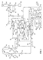
- FIG. 1 Shown in Figure 1 is a diagrammatic view of an analyzer system for measuring total carbon dioxide in samples of biological liquids such as serum or plasma that includes analysis unit 10 that has pH electrode 12 and reference electrode 14 that are connected to processor 16 in system controller 18. Processor 16 is connected to apply outputs to display 20 and controller 18 has inputs from keyboard 22.
- That analyzer system is incorporated in a system for measuring other parameters of bioligical fluids, and further aspects of that system may be seen with reference to copending applications Serial No. entitled SAMPLE ANALYSIS (Case 308 ), and Serial No. entitled LIQUID HANDLING (Case 316 ), and filed concurrently herewith, the disclosures of which are specifically incorporated herein by reference.
- gas diffusion unit 30 that has inlet 32 for buffer liquid stream and inlet 34 for an reagent liquid stream into which a sample to be analyzed has been inserted.
- the reagent liquid flows from inlet 34 through tubing coil 36, diffusion channel structure 38 and line 40 to drip isolator 42.
- the buffer liquid similarly flows from inlet 32 through tubing coil 43 and diffusion channel structure 44. Clamped between diffusion channel structures 38 and 44 is diffusion membrane 50 across which gas diffuses from the reagent stream to the buffer stream.
- the buffer stream then flows through optional coil 46 and line 48 to analysis unit 10 for sensing by pH and reference electrodes 12 and 14 and then is discharged to drip isolator 42 to which atmospheric pressure is at nine inches of mercury from manifold 52 is applied under control of valve 54 to empty drip isolator 42.
- Chamber 58 and pump 60 apply reduced pressure to manifold 52.
- Module 66 has a reagent liquid inlet port 68, a sample chamber 70 that is closed by valve 72, input 74 from a source of buffer liquid over line 76, input 78 from a source of reagent over line 79, and outlet 80 that is connected by line 82 to the reduced pressure manifold 52.
- a sample introduction system includes sample probe 84 that is mounted for movement by drive 86 between a sample container 88 (an array of sample containers 88 being disposed on turntable 90), wash cup 92 (that is connected to vacuum manifold 52 via valve 94), and valve 72 of sample chamber 70 of sample insertion module 66. Further details of valve 72 and the probe system may be seen with reference to copending applications Serial No. , entitled FLUID HANDLNG (Case 317 ) and Serial No. , entitled LIQUID HANDLING (Case 316 ), filed concurrently herewith, the disclosures of which are specifically incorporated herein by reference.
- Sample probe 84 is connected via line 96 and valve 98 to the outlet 100 of metering syringe pump 102 whose piston is operated by stepper motor 104.
- Pump outlet 100 is also connected via valve 106 to reservoir 108 of de-ionized water.
- a source 110 of reagent liquid (nine millimol per liter sulfuric acid) is connected via valve 112 to outlet 114 of one milliliter capacity syringe pump 116; and a source 118 of buffer liquid (twelve millimol per liter sodium bicarbonate) is connected via valve 120 to outlet 122 of one half milliliter capacity syringe pump 124.
- Common stepper motor drive 126 moves the pistons of syringe pumps 116 and 124 in synchronism to provide concurrent flow of acid reagent and buffer liquid from the outlets of pumps 116 and 124 over lines 128, 130, respectively, the reagent liquid flow rate being twice that of the buffer liquid.
- Line 130 is connected via valve 132 to preheater coil 134 in preheater unit 136 that is maintained at a temperature of about 36°C and line 128 is connected via valve 137 to a similar preheater coil 138 in preheater unit 136.
- the heated reagent and buffer liquids are concurrently flowed from preheater unit 136 through Goretex vent tube sections 140, 142 to inlet 68 of the sample insertion module 66 and inlet 32 of the gas diffusion unit 30, respectively.
- Sample insertion module 66 includes an array of valves 150 of the type shown in Webster U.S. Patent 4,304,257 and Webster U.S. Patent No. 4,601,881, the disclosures of which are also specifically incorporated herein by reference, valves 150 (and valves 54, 94, 98, 106, 112, 120, 132 and 137) being operated by signals over lines 152 from controller 18.
- Sample insertion module 66 includes a reagent circuit 154 that extends from isolation valve 150-3, through transfer valve 150-4, metering chamber passage 156 (of ten microliter volume), transfer valve 150-6, isolation valve 150-8 and shunt valve 150-10 to outlet 62.
- Shunt circuit 158 is controlled by valve 150-10, reagent circuit 154 and metering chamber 156 being shunted when valve 150-10 is operated to open the shunt path from inlet 68 to outlet 64.
- a sample circuit 160 extends from sample chamber 70 through transfer valve 150-4 and isolation valve 150-7 to reduced pressure reservoir channel 162 that is coupled by isolation valve 150-11 to outlet 80 that is connected to vacuum manifold 52 over line 82.
- Channel region 162 between isolation valves 150-7 and 150-11 provides a reduced pressure reservoir for controlled flow of liquid.
- Auxiliary circuit 164 extends from isolation valve 150-5 through transfer valve 150-6 to selector valve 150-9 that connects the auxiliary circuit 164 to the reduced pressure reservoir circuit 162.
- a vent circuit 166 extends from the top of sample chamber 70 through selector valve 150-2 to vent valve 150-1.
- valve 150-2 When valve 150-2 is open, buffer solution may be applied to vent circuit 166, sample chamber 70 and sample circuit 160; and when isolation valve 150-5 is opened, reagent may similarly be applied to auxiliary circuit 164.
- sample insertion module 66 includes acrylic face plate 172.
- Sheet membrane 174 is clamped against the rear surface of face plate 172 by backer plate 176 and structure 178 supports an array of electric solenoids (not shown) that operate actuators 180.
- Each actuator has a head 182 that is embedded in the membrane sheet 174 at a valve position and a spring 184 seated between the actuator head 182 and support plate 178 maintains the membrane 174 in seated valve closed position against the lands 170 of the respective transfer, selector, isolation and vent valves.
- Energization of its electric solenoid moves the actuator 180 away from face plate 172 and opens the valve to permit flow of fluid across the valve land 170.
- the spring 184 moves the actuator 180 towards the face plate 172 in a gentle and smooth closing action with the membrane 174 moving in a radially inward direction so that there is essentially zero dead space when the valve is closed and excellent isolation between liquids in adjacent channels is provided.
- Metering chamber 156 of about ten microliters volume is formed by the reagent circuit channel section between the transfer valves 150-4 and 150-6.
- the reagent circuit 154 is provided by a channel in the acrylic face plate 172 that has a width of 0.8 millimeter and a depth of about one half millimeter.
- Sample circuit 160 and auxiliary circuit 164 each includes a parallel channel through the corresponding transfer valve that has a depth of about one half millimeter and a width of about one half millimeter.
- Channels 154 and 160 are spaced apart by land 170-4 of valve 150-4 that has a width of less than one millimeter, and the lands 170 of the other valves are of similar width.
- That difussion assembly includes aluminum housing members 190, 192 which receive acrylic diffusion channel structures 38, 44, each of which has a spiral flow channel 194 formed on its surface, each channel 194 having a length of about eight centimeters, a width of about two millimeters and a depth of about 0.2 millimeter.
- Guide posts 196 extend between housing members 190, 192 and position diffusion channel structures 38, 44 with the flow channels 194A, 194B in alignment.
- Housing member 190 has a chamber region in which 0.5 millimeter ID Teflon reagent tubing 204 extends from inlet 34 through a three turn coil 36 of about 2 1/2 centimeter diameter, tube fitting 206 which is coupled to 0.5 millimeter diameter flow channel 208 that extends to inlet end 210A of the spiral channel 194A.
- the outlet end 212A of channel 194A is connected through channel 214 and fitting 216 to tube 40.
- the buffer fluid tube 220 is coupled by fitting 222 and channel 224 to inlet end 210B of flow channel 194B and its outlet end 212B is coupled by channel 226 and fitting 228 through optional tubing coil 46 and line 48 to measurement module 10 for flow of the transport buffer past pH electrode 12 and reference electrode 14.
- Heater pad 230 is mounted on housing member 192 and thermistor 232 is embedded in housing block 190 to monitor the temperature of the diffusion gas assembly 30, controller 18 maintaining the temperature of assembly 30 at 35°C.
- probe 84 (Fig. 1) (that has previously been filled with diluent from reservoir 108) is rinsed at wash cup 92 and then is moved to the sample station to draw up about two microliters of air and then an appropriate quantity (depending on analyses to be preformed at other modules of the system) of sample from sample cup 88. Probe 84 is then moved by drive 86 to the sample insertion module 66 where valve 72 is opened and a thirty-five microliter volume of sample 250 is injected into chamber 70 (as indicated in Fig. 7A) by pump 102.
- buffer syringe pump 124 has been filled with one half milliliter of bicarbonate buffer and reagent syringe pump 116 has been filled with one milliliter of sulfuric acid reagent (see Fig. 1).
- 300 microliters of acid and 150 microliters of buffer are flowed by operation of the syringe drive 126 through preheater 136 to shunt circuit 158 through valve 150-10 to gas diffusion assembly 30. Since valves 150-3 and 150-8 are closed during this preflush, reagent 252 is immobilized in the reagent circuit 154 and metering chamber 156. Vent valve 150-1 is opened to expose the surface of sample 250 in chamber 70 to atmosphere.
- valve 150-11 is closed to trap that reduced pressure in manifold channel 162 and valve 150-7 is opened so that the reduced pressure draws sample 250 from chamber 70 along sample channel 160 through transfer valve 150-4 (which is not open at this time) toward isolation valve 150-7.
- Valve 150-7 is then closed, the reservoir channel 162 is recharged with reduced pressure and the cycle repeated to draw sample 250 further towards valve 150-7 as indicated in Figure 7B. After completion of flowing of sample 250 through sample channel 160, past valve site 150-4 towards valve 150-7, reservoir channel 162 is again recharged.
- Transfer valves 150-4 and 150-6 and control valve 150-9 are then opened, and the reduced pressure in channel 162 draws reagent 252 from metering chamber 156 into auxiliary channel 164 and replaces that reagent with sample 250 from the sample channel 160. Transfer valves 150-4, 150-6 are then closed. As indicated in Figure 7C, isolating leading and trailing edge portions of the sample 250 in channels 160 and 164 with a quantity of sample 250 inserted into the metering chamber portion 156 of the reagent circuit 154 as a plug (and without air bubble isolation or segmentation) into the reagent stream 252.
- syringe pumps 116 and 124 are operated synchronously by drive 126 for about twenty four seconds to flow reagent 252 at a 1.1 milliliter per minute reagent flow rate through inlet 68 and outlet 64 via shunt circuit 158, and a corresponding flow of buffer at a 0.56 milliliter per minute rate to gas diffusion unit 30.
- valves 150-3 and 150-8 are opened and fifty microseconds later, valve 150-10 is closed to interrupt the shunt channel 158 so that the reagent circuit with the inserted sample 250 is flowed (as indicated in Fig. 7D) along tube 62 and through mixing coil 36 to diffusion channel structure 38.
- the acid reagent 252 and sample 250 are subjected to radial dispersion and bolus mixing and the acid in reagent 252 reacts with serum in sample 250 in the flowing stream to produce carbonic acid which releases carbon dioxide.
- the released carbon dioxide in the reagent stream in flow channel 194A diffuses across membrane 50 into the sodium bicarbonate buffer stream in flow channel 194B for transport past the pH and reference electrodes 12 and 14 at a positive buffer flow rate of 0.56 milliliter per minute.
- Controller 18 begins a data acquisition sequence about three seconds before the peak output signal to establish a base line and data acquisition continues for about ten seconds such that the output signal is followed past its maximum.
- the peak height is found by averaging five data points at a time and then taking the highest and lowest average of those data points.
- the difference between the base line (lowest average) and peak (highest average) is the delta or peak height which is directly proportional to total carbon dioxide concentration in the sample being analyzed.
- the syringe pumps 116, 124 flow acid and buffer at a 4.7 milliliter per minute acid flow rate (2.35 millimeter buffer flow rate) for about eight seconds to flush the system, reagent being also flowed through port 78 and isolation valve 150-5 under the influence of reduced pressure from manifold 52 to flush the auxiliary channel 164.
- Buffer solution is similarly drawn by reduced pressure through port 74 and selector valves 150-2, 150-7 and 150-11 to flush sample line 160 and sample chamber 70. Vent valve 150-1 is then opened and selector valve 150-2 closed to dry the sample chamber 70 and sample line 160, and the system is ready for the next cycle.
Landscapes
- General Health & Medical Sciences (AREA)
- Health & Medical Sciences (AREA)
- Life Sciences & Earth Sciences (AREA)
- Chemical & Material Sciences (AREA)
- Analytical Chemistry (AREA)
- Biochemistry (AREA)
- Physics & Mathematics (AREA)
- General Physics & Mathematics (AREA)
- Immunology (AREA)
- Pathology (AREA)
- Automatic Analysis And Handling Materials Therefor (AREA)
- Sampling And Sample Adjustment (AREA)
- Feeding, Discharge, Calcimining, Fusing, And Gas-Generation Devices (AREA)
Applications Claiming Priority (2)
| Application Number | Priority Date | Filing Date | Title |
|---|---|---|---|
| US75052 | 1987-07-17 | ||
| US07/075,052 US4859422A (en) | 1987-07-17 | 1987-07-17 | Analysis system |
Publications (2)
| Publication Number | Publication Date |
|---|---|
| EP0299658A2 true EP0299658A2 (de) | 1989-01-18 |
| EP0299658A3 EP0299658A3 (de) | 1990-05-16 |
Family
ID=22123229
Family Applications (1)
| Application Number | Title | Priority Date | Filing Date |
|---|---|---|---|
| EP88306085A Withdrawn EP0299658A3 (de) | 1987-07-17 | 1988-07-04 | Analysesystem |
Country Status (3)
| Country | Link |
|---|---|
| US (1) | US4859422A (de) |
| EP (1) | EP0299658A3 (de) |
| JP (1) | JPS6449968A (de) |
Cited By (3)
| Publication number | Priority date | Publication date | Assignee | Title |
|---|---|---|---|---|
| EP0388018A2 (de) * | 1989-03-13 | 1990-09-19 | Beckman Instruments, Inc. | Probeneinspritzzelle |
| EP0660115A2 (de) * | 1989-03-13 | 1995-06-28 | Beckman Instruments, Inc. | Automatische chemische Analysevorrichtung |
| DE102007028116B3 (de) * | 2007-06-19 | 2008-11-20 | Siemens Ag | Mikrofluidiksystem zum Mischen von mindestens zwei Ausgangsstoffen |
Families Citing this family (15)
| Publication number | Priority date | Publication date | Assignee | Title |
|---|---|---|---|---|
| US5037737A (en) * | 1988-06-29 | 1991-08-06 | Apec, Inc. | Analysis by sensor placement in recprocating flow |
| JP2630005B2 (ja) * | 1990-03-23 | 1997-07-16 | 日本電気株式会社 | 液体成分測定装置および測定方法 |
| US6562605B1 (en) * | 1995-11-13 | 2003-05-13 | Genencor International, Inc. | Extraction of water soluble biomaterials from fluids using a carbon dioxide/surfactant mixture |
| US5849598A (en) * | 1996-03-15 | 1998-12-15 | Washington University | Method for transferring micro quantities of liquid samples to discrete locations |
| FR2762092B1 (fr) * | 1997-04-15 | 1999-05-28 | Bio Merieux | Procede et dispositif de remplissage avec un milieu liquide d'une carte d'analyse |
| US6392109B1 (en) | 2000-02-29 | 2002-05-21 | Chevron U.S.A. Inc. | Synthesis of alkybenzenes and synlubes from Fischer-Tropsch products |
| US6566569B1 (en) | 2000-06-23 | 2003-05-20 | Chevron U.S.A. Inc. | Conversion of refinery C5 paraffins into C4 and C6 paraffins |
| US6441263B1 (en) | 2000-07-07 | 2002-08-27 | Chevrontexaco Corporation | Ethylene manufacture by use of molecular redistribution on feedstock C3-5 components |
| US20030131731A1 (en) | 2001-12-20 | 2003-07-17 | Koros William J. | Crosslinked and crosslinkable hollow fiber mixed matrix membrane and method of making same |
| US7543598B1 (en) | 2005-12-29 | 2009-06-09 | Group Dekko, Inc. | Vacuum break thermistor housing |
| JP2009014439A (ja) * | 2007-07-03 | 2009-01-22 | Fujirebio Inc | 物質移動制御デバイス |
| JP5506440B2 (ja) * | 2010-02-08 | 2014-05-28 | 株式会社堀場製作所 | 液体試料定量器 |
| DE102019120415A1 (de) * | 2019-07-29 | 2021-02-04 | Endress+Hauser Conducta Gmbh+Co. Kg | Verfahren zur Bestimmung einer chemischen Aufnahmekapazität eines Prozessmediums in einer Messstelle sowie Messstelle zur Bestimmung einer chemischen Aufnahmekapazität eines Prozessmediums |
| US11529617B2 (en) | 2020-08-12 | 2022-12-20 | Chevron Phillips Chemical Company, Lp | Catalyst supports and catalyst systems and methods |
| CN114878846B (zh) * | 2022-07-08 | 2022-11-22 | 深圳市帝迈生物技术有限公司 | 一种血液分析仪及其清洗方法 |
Citations (6)
| Publication number | Priority date | Publication date | Assignee | Title |
|---|---|---|---|---|
| US3572994A (en) * | 1968-02-27 | 1971-03-30 | Technicon Corp | Analysis system for a liquid stream for a gaseous constituent |
| US4119120A (en) * | 1976-11-29 | 1978-10-10 | Beckman Instruments, Inc. | Fluid switch |
| US4177677A (en) * | 1976-09-13 | 1979-12-11 | Bifok Ab | Sample supply to automatic analyzers |
| US4304257A (en) * | 1980-07-01 | 1981-12-08 | Instrumentation Laboratory Inc. | Valve with flexible sheet member |
| EP0107631A2 (de) * | 1982-09-28 | 1984-05-02 | Bifok Ab | Integrierte Mikrokanalisation für kontinuierliche Durchflussanalyse |
| US4601881A (en) * | 1984-11-01 | 1986-07-22 | Allied Corporation | Liquid handling system |
Family Cites Families (8)
| Publication number | Priority date | Publication date | Assignee | Title |
|---|---|---|---|---|
| US4013413A (en) * | 1975-07-10 | 1977-03-22 | The United States Of America As Represented By The Secretary Of Agriculture | Apparatus and method for rapid analyses of plurality of samples |
| SE414872B (sv) * | 1977-10-03 | 1980-08-25 | Bifok Ab | Forfarande och anordning vid flodesinjektionsextraktion |
| US4209299A (en) * | 1978-02-21 | 1980-06-24 | The Regents Of The University Of California | Method and apparatus for determination of volatile electrolytes |
| SE418017B (sv) * | 1978-06-14 | 1981-04-27 | Bifok Ab | Sett att kontinuerligt bestemma olika langsamt reagerande substanser kvantitativt med anvendning av en enda metcell |
| US4315754A (en) * | 1979-08-28 | 1982-02-16 | Bifok Ab | Flow injection analysis with intermittent flow |
| US4299794A (en) * | 1980-06-20 | 1981-11-10 | Instrumentation Laboratory Inc. | Analytical system for analyzing CO2 content of a fluid |
| US4607526A (en) * | 1984-12-21 | 1986-08-26 | Allied Corporation | Particle analysis system |
| US4640821A (en) * | 1985-07-16 | 1987-02-03 | Fisher Scientific Company | Analysis apparatus |
-
1987
- 1987-07-17 US US07/075,052 patent/US4859422A/en not_active Expired - Fee Related
-
1988
- 1988-07-04 EP EP88306085A patent/EP0299658A3/de not_active Withdrawn
- 1988-07-18 JP JP63178919A patent/JPS6449968A/ja active Pending
Patent Citations (6)
| Publication number | Priority date | Publication date | Assignee | Title |
|---|---|---|---|---|
| US3572994A (en) * | 1968-02-27 | 1971-03-30 | Technicon Corp | Analysis system for a liquid stream for a gaseous constituent |
| US4177677A (en) * | 1976-09-13 | 1979-12-11 | Bifok Ab | Sample supply to automatic analyzers |
| US4119120A (en) * | 1976-11-29 | 1978-10-10 | Beckman Instruments, Inc. | Fluid switch |
| US4304257A (en) * | 1980-07-01 | 1981-12-08 | Instrumentation Laboratory Inc. | Valve with flexible sheet member |
| EP0107631A2 (de) * | 1982-09-28 | 1984-05-02 | Bifok Ab | Integrierte Mikrokanalisation für kontinuierliche Durchflussanalyse |
| US4601881A (en) * | 1984-11-01 | 1986-07-22 | Allied Corporation | Liquid handling system |
Cited By (6)
| Publication number | Priority date | Publication date | Assignee | Title |
|---|---|---|---|---|
| EP0388018A2 (de) * | 1989-03-13 | 1990-09-19 | Beckman Instruments, Inc. | Probeneinspritzzelle |
| EP0388018A3 (de) * | 1989-03-13 | 1991-06-05 | Beckman Instruments, Inc. | Probeneinspritzzelle |
| EP0660115A2 (de) * | 1989-03-13 | 1995-06-28 | Beckman Instruments, Inc. | Automatische chemische Analysevorrichtung |
| EP0660115A3 (de) * | 1989-03-13 | 1995-08-09 | Beckman Instruments Inc | Automatische chemische Analysevorrichtung. |
| DE102007028116B3 (de) * | 2007-06-19 | 2008-11-20 | Siemens Ag | Mikrofluidiksystem zum Mischen von mindestens zwei Ausgangsstoffen |
| US8163245B2 (en) | 2007-06-19 | 2012-04-24 | Siemens Aktiengesellschaft | Microfluidics system for mixing at least two starting materials |
Also Published As
| Publication number | Publication date |
|---|---|
| EP0299658A3 (de) | 1990-05-16 |
| JPS6449968A (en) | 1989-02-27 |
| US4859422A (en) | 1989-08-22 |
Similar Documents
| Publication | Publication Date | Title |
|---|---|---|
| US4859422A (en) | Analysis system | |
| US4906432A (en) | Liquid handling | |
| JP4216712B2 (ja) | マイクロ流体式化学検定装置および方法 | |
| JP3256818B2 (ja) | 試料液体分析装置及び試料液体分析法 | |
| EP0098550B1 (de) | Verfahren und Vorrichtung zur Durchfluss-Analyse | |
| CN100534619C (zh) | 对可通过导管进入测量室中的液态测量样品进行电化学测量的方法和相应的布置 | |
| US7125711B2 (en) | Method and apparatus for splitting of specimens into multiple channels of a microfluidic device | |
| EP2972331B1 (de) | Mikrofluidische verteilungsvorrichtung | |
| US6919045B1 (en) | Supply element for a laboratory microchip | |
| US20060002827A1 (en) | Liquid reservoir connector | |
| US20010027918A1 (en) | Method for monitoring flow rate using fluorescent markers | |
| US20040265172A1 (en) | Method and apparatus for entry and storage of specimens into a microfluidic device | |
| US20050006238A1 (en) | Pressure induced reagent introduction and electrophoretic separation | |
| US4624928A (en) | Liquid handling process | |
| US20080257754A1 (en) | Method and apparatus for entry of specimens into a microfluidic device | |
| US4607526A (en) | Particle analysis system | |
| JPH0783935A (ja) | 化学分析装置 | |
| US8323573B2 (en) | Microfluidic cartridge with solution reservoir-pump chamber | |
| US10246675B2 (en) | Biochemical cartridge, and biochemical cartridge and cartridge holder set | |
| EP1614464A1 (de) | Verbindungsstück zwischen Flüssigkeitsbehältern | |
| EP0183950B1 (de) | Verfahren zur Behandlung einer Flüssigkeit in einem Rohr | |
| US20060078471A1 (en) | Apparatus and method for a precision flow assay | |
| US20020110926A1 (en) | Emulator device | |
| US20060210961A1 (en) | Method and system for analysing a liquid sample | |
| CN217542822U (zh) | 样本检测系统 |
Legal Events
| Date | Code | Title | Description |
|---|---|---|---|
| PUAI | Public reference made under article 153(3) epc to a published international application that has entered the european phase |
Free format text: ORIGINAL CODE: 0009012 |
|
| AK | Designated contracting states |
Kind code of ref document: A2 Designated state(s): AT BE CH DE ES FR GB IT LI NL SE |
|
| PUAL | Search report despatched |
Free format text: ORIGINAL CODE: 0009013 |
|
| AK | Designated contracting states |
Kind code of ref document: A3 Designated state(s): AT BE CH DE ES FR GB IT LI NL SE |
|
| 17P | Request for examination filed |
Effective date: 19900628 |
|
| RAP1 | Party data changed (applicant data changed or rights of an application transferred) |
Owner name: IL HOLDING S.P.A. |
|
| 17Q | First examination report despatched |
Effective date: 19920813 |
|
| RAP1 | Party data changed (applicant data changed or rights of an application transferred) |
Owner name: INSTRUMENTATION LABORATORY S.P.A. |
|
| STAA | Information on the status of an ep patent application or granted ep patent |
Free format text: STATUS: THE APPLICATION IS DEEMED TO BE WITHDRAWN |
|
| 18D | Application deemed to be withdrawn |
Effective date: 19940201 |