EP0298937B1 - Tool for metal cutting - Google Patents
Tool for metal cutting Download PDFInfo
- Publication number
- EP0298937B1 EP0298937B1 EP88850180A EP88850180A EP0298937B1 EP 0298937 B1 EP0298937 B1 EP 0298937B1 EP 88850180 A EP88850180 A EP 88850180A EP 88850180 A EP88850180 A EP 88850180A EP 0298937 B1 EP0298937 B1 EP 0298937B1
- Authority
- EP
- European Patent Office
- Prior art keywords
- cutting body
- cutting
- locking screw
- tool
- recess
- Prior art date
- Legal status (The legal status is an assumption and is not a legal conclusion. Google has not performed a legal analysis and makes no representation as to the accuracy of the status listed.)
- Expired - Lifetime
Links
- 239000002184 metal Substances 0.000 title claims description 5
- 210000002105 tongue Anatomy 0.000 claims 7
- 238000005553 drilling Methods 0.000 description 3
- 238000003801 milling Methods 0.000 description 2
- 238000007514 turning Methods 0.000 description 2
- 238000003754 machining Methods 0.000 description 1
- 238000000034 method Methods 0.000 description 1
Images

Classifications
-
- B—PERFORMING OPERATIONS; TRANSPORTING
- B23—MACHINE TOOLS; METAL-WORKING NOT OTHERWISE PROVIDED FOR
- B23C—MILLING
- B23C5/00—Milling-cutters
- B23C5/02—Milling-cutters characterised by the shape of the cutter
- B23C5/10—Shank-type cutters, i.e. with an integral shaft
-
- B—PERFORMING OPERATIONS; TRANSPORTING
- B23—MACHINE TOOLS; METAL-WORKING NOT OTHERWISE PROVIDED FOR
- B23C—MILLING
- B23C5/00—Milling-cutters
- B23C5/16—Milling-cutters characterised by physical features other than shape
-
- B—PERFORMING OPERATIONS; TRANSPORTING
- B23—MACHINE TOOLS; METAL-WORKING NOT OTHERWISE PROVIDED FOR
- B23B—TURNING; BORING
- B23B31/00—Chucks; Expansion mandrels; Adaptations thereof for remote control
- B23B31/02—Chucks
- B23B31/10—Chucks characterised by the retaining or gripping devices or their immediate operating means
- B23B31/11—Retention by threaded connection
- B23B31/1107—Retention by threaded connection for conical parts
- B23B31/1122—Retention by threaded connection for conical parts using cylindrical threads
-
- B—PERFORMING OPERATIONS; TRANSPORTING
- B27—WORKING OR PRESERVING WOOD OR SIMILAR MATERIAL; NAILING OR STAPLING MACHINES IN GENERAL
- B27G—ACCESSORY MACHINES OR APPARATUS FOR WORKING WOOD OR SIMILAR MATERIALS; TOOLS FOR WORKING WOOD OR SIMILAR MATERIALS; SAFETY DEVICES FOR WOOD WORKING MACHINES OR TOOLS
- B27G13/00—Cutter blocks; Other rotary cutting tools
- B27G13/002—Rotary tools without insertable or exchangeable parts, except the chucking part
-
- B—PERFORMING OPERATIONS; TRANSPORTING
- B23—MACHINE TOOLS; METAL-WORKING NOT OTHERWISE PROVIDED FOR
- B23B—TURNING; BORING
- B23B2240/00—Details of connections of tools or workpieces
- B23B2240/36—Connections using a tongue and a hollow of corresponding prismatic form
-
- B—PERFORMING OPERATIONS; TRANSPORTING
- B23—MACHINE TOOLS; METAL-WORKING NOT OTHERWISE PROVIDED FOR
- B23C—MILLING
- B23C2210/00—Details of milling cutters
- B23C2210/03—Cutting heads comprised of different material than the shank irrespective of whether the head is detachable from the shank
-
- F—MECHANICAL ENGINEERING; LIGHTING; HEATING; WEAPONS; BLASTING
- F16—ENGINEERING ELEMENTS AND UNITS; GENERAL MEASURES FOR PRODUCING AND MAINTAINING EFFECTIVE FUNCTIONING OF MACHINES OR INSTALLATIONS; THERMAL INSULATION IN GENERAL
- F16B—DEVICES FOR FASTENING OR SECURING CONSTRUCTIONAL ELEMENTS OR MACHINE PARTS TOGETHER, e.g. NAILS, BOLTS, CIRCLIPS, CLAMPS, CLIPS OR WEDGES; JOINTS OR JOINTING
- F16B2200/00—Constructional details of connections not covered for in other groups of this subclass
- F16B2200/40—Clamping arrangements where clamping parts are received in recesses of elements to be connected
- F16B2200/403—Threaded clamping parts
-
- Y—GENERAL TAGGING OF NEW TECHNOLOGICAL DEVELOPMENTS; GENERAL TAGGING OF CROSS-SECTIONAL TECHNOLOGIES SPANNING OVER SEVERAL SECTIONS OF THE IPC; TECHNICAL SUBJECTS COVERED BY FORMER USPC CROSS-REFERENCE ART COLLECTIONS [XRACs] AND DIGESTS
- Y10—TECHNICAL SUBJECTS COVERED BY FORMER USPC
- Y10T—TECHNICAL SUBJECTS COVERED BY FORMER US CLASSIFICATION
- Y10T279/00—Chucks or sockets
- Y10T279/16—Longitudinal screw clamp
-
- Y—GENERAL TAGGING OF NEW TECHNOLOGICAL DEVELOPMENTS; GENERAL TAGGING OF CROSS-SECTIONAL TECHNOLOGIES SPANNING OVER SEVERAL SECTIONS OF THE IPC; TECHNICAL SUBJECTS COVERED BY FORMER USPC CROSS-REFERENCE ART COLLECTIONS [XRACs] AND DIGESTS
- Y10—TECHNICAL SUBJECTS COVERED BY FORMER USPC
- Y10T—TECHNICAL SUBJECTS COVERED BY FORMER US CLASSIFICATION
- Y10T279/00—Chucks or sockets
- Y10T279/17—Socket type
- Y10T279/17863—Shouldered-tang holding
-
- Y—GENERAL TAGGING OF NEW TECHNOLOGICAL DEVELOPMENTS; GENERAL TAGGING OF CROSS-SECTIONAL TECHNOLOGIES SPANNING OVER SEVERAL SECTIONS OF THE IPC; TECHNICAL SUBJECTS COVERED BY FORMER USPC CROSS-REFERENCE ART COLLECTIONS [XRACs] AND DIGESTS
- Y10—TECHNICAL SUBJECTS COVERED BY FORMER USPC
- Y10T—TECHNICAL SUBJECTS COVERED BY FORMER US CLASSIFICATION
- Y10T279/00—Chucks or sockets
- Y10T279/17—Socket type
- Y10T279/17931—Screw threaded
-
- Y—GENERAL TAGGING OF NEW TECHNOLOGICAL DEVELOPMENTS; GENERAL TAGGING OF CROSS-SECTIONAL TECHNOLOGIES SPANNING OVER SEVERAL SECTIONS OF THE IPC; TECHNICAL SUBJECTS COVERED BY FORMER USPC CROSS-REFERENCE ART COLLECTIONS [XRACs] AND DIGESTS
- Y10—TECHNICAL SUBJECTS COVERED BY FORMER USPC
- Y10T—TECHNICAL SUBJECTS COVERED BY FORMER US CLASSIFICATION
- Y10T408/00—Cutting by use of rotating axially moving tool
- Y10T408/89—Tool or Tool with support
- Y10T408/907—Tool or Tool with support including detailed shank
-
- Y—GENERAL TAGGING OF NEW TECHNOLOGICAL DEVELOPMENTS; GENERAL TAGGING OF CROSS-SECTIONAL TECHNOLOGIES SPANNING OVER SEVERAL SECTIONS OF THE IPC; TECHNICAL SUBJECTS COVERED BY FORMER USPC CROSS-REFERENCE ART COLLECTIONS [XRACs] AND DIGESTS
- Y10—TECHNICAL SUBJECTS COVERED BY FORMER USPC
- Y10T—TECHNICAL SUBJECTS COVERED BY FORMER US CLASSIFICATION
- Y10T408/00—Cutting by use of rotating axially moving tool
- Y10T408/94—Tool-support
- Y10T408/95—Tool-support with tool-retaining means
- Y10T408/957—Tool adapter
Definitions
- This invention relates to a tool for metal cutting, said tool comprising a cutting body and a shaft that supports the cutting body, said cutting body having at least one cutting edge that is integral with the cutting body, said cutting body being detachably connected to a locking screw via hook-shaped means, said hook-shaped means transferring axial forces between the cutting body and the locking screw, said locking screw being provided with an externally threaded portion that is connected to an internally threaded recess provided in said shaft, said locking screw being movable in axial direction by relative rotation of the externally threaded portion and the internally threaded recess, said threaded portions being designed as right hand threads for right hand cutting tools and as left hand threads for left hand cutting tools as defined in the precharacterizing portion of claim 1, see GB-A-990 353.
- the invention also relates to a cutting body per se according to the precharacterizing portion of claim 5, see GB-A-990 353.
- a device for securing a tool to a machine tool spindle Said device transfers axial forces between a tool holder and a locking element.
- said device can only to a limited extent transfer rotational movement between said tool holder and said locking element. This gives rise to problems in respect of handling and securing.
- the aim of the present invention is to present a design for milling, drilling and turning tools of small dimensions having exchangeable cutting edges, said design avoiding the problems of the known prior art.
- Fig. 1 discloses the elements of a tool according to the invention before they are mounted together;
- Fig. 2 discloses a tool according to the invention in mounted position;
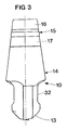
- Fig. 3 discloses in greater detail a side view of a cutting body according to the invention.
- the embodiment disclosed in Figs 1 and 2 of a tool according to the invention comprises a cutting body 10, a locking screw 11 and a shaft 12.
- the end 13 of the cutting body 10 that is directed from the shaft 12 is provided with at least one cutting edge that can be given different designs due to the field of application.
- the cutting edge or edges are straight and parallel to the longitudinal centre axis of the cutting body when dealing with a shank end mill while the cutting edges are circular when dealing with a radial mill.
- the enumeration is only exemplifying and the front end of the cutting body 10 is not shown in detail in Figs 1 and 2 since it can be varied in many ways and does not constitute an essential part of the present invention.
- a first conical portion 14 is provided that has a first engagment means 15 comprising a first tonque 16 and a first recess 17.
- Fig. 3 the cutting body 10 is disclosed more in detail and viewed in the plane of the paper in Figs 1 and 2. From Fig. 3 it can be learnt that the free end 13 of the cutting body 10 is provided with a key handle 32. The use of said key handle 32 is explained below.
- the locking screw 11 has a second conical portion at the end that is directed towards the cutting body, said second conical portion having a second engagement means 19 that is intended to cooperate with the first engagement means 15.
- the second engagement means 19 comprises a second tongue 20 and a second recess 21. In working condition the first tongue 16 cooperates with the second recess 21 and the second tongue 20 with the first recess 17.
- the locking screw 11 Inside of the second engagment means 18, in axial direction, the locking screw 11 has an externally threaded, preferably cylindrical portion 22.
- An Allen key insert 23 is arranged at the innermost end of the locking screw 11 thus making it possible to loosen and tighten the locking screw 11 through the internal duct 24 of the shaft 12. However, normally the tightening and loosening of the locking screw 11 is carried out via the external key handle 32.
- the shaft 12 is provided with a conical seat 25 at the end that is directed towards the cutting body 10. Said conical seat 25 receives the first and second conical portions 14 and 18 of the cutting body 10 and the locking screw 11, respectively. Inside of the conical seat 25 the shaft 12 has a substantially cylindrical, internally threaded portion 26 that cooperates with the externally threaded portion 22 on the locking screw 11. Inside of the portion 26 the duct 24 mentioned above is located.
- Fig. 1 the starting position for mounting of the cutting body 10 in the shaft 12 is disclosed.
- the locking screw 11 is displaced axially towards the open end of the conical seat 25.
- the first engagement means 15 of the cutting body 10 is inserted into the conical seat 25 and automatically takes a position for engagement with the second engagment means of the locking screw 11.
- the locking screw 11 will also rotate in the direction of the arrow 27.
- Cooperation between the external thread 22 and the internal thread 26 causes the locking screw 11 and also the cutting body 10 to be displaced axially into the shaft 12 until the conical portion 14 contacts the conical seat 25, i.e. the position according to Fig. 2 has been achieved.
- the cutting body 10 is now in a satisfying way anchored in the shaft 12.
- the thread 22 of the locking screw 11 has two purposes, namely first to place the cutting body 10 in a fixed position in the shaft in the mounting state, and second, during use of the cutting tool, always to guarantee that the cutting body 10 remains in its fixed position regardless of how the dimensions of the cutting body 10 and the shaft 12 are affected by heat generated from the machining.
- the threads 22 and 26 are designed as right hand threads for right hand cutting tools and as left hand threads for left hand cutting tools.
- the cone angle for the cutting body and the seat should be less than 25°. It is also pointed out that the embodiment described above refer to a mill, i.e. a tool that rotates relative to its longitudinal centre axis. Mills having small cutting tips are probably the dominating application field for the present invention but also drilling and turning tools are within the scope of the invention.
Landscapes
- Engineering & Computer Science (AREA)
- Mechanical Engineering (AREA)
- Life Sciences & Earth Sciences (AREA)
- Wood Science & Technology (AREA)
- Forests & Forestry (AREA)
- Milling Processes (AREA)
- Food-Manufacturing Devices (AREA)
- Drilling Tools (AREA)
Applications Claiming Priority (2)
| Application Number | Priority Date | Filing Date | Title |
|---|---|---|---|
| SE8702799A SE457935B (sv) | 1987-07-08 | 1987-07-08 | Verktyg foer skaerande bearbetning samt skaerdel foer verktyget |
| SE8702799 | 1987-07-08 |
Publications (2)
| Publication Number | Publication Date |
|---|---|
| EP0298937A1 EP0298937A1 (en) | 1989-01-11 |
| EP0298937B1 true EP0298937B1 (en) | 1992-10-28 |
Family
ID=20369085
Family Applications (1)
| Application Number | Title | Priority Date | Filing Date |
|---|---|---|---|
| EP88850180A Expired - Lifetime EP0298937B1 (en) | 1987-07-08 | 1988-05-25 | Tool for metal cutting |
Country Status (5)
| Country | Link |
|---|---|
| US (2) | US4850759A (enExample) |
| EP (1) | EP0298937B1 (enExample) |
| JP (1) | JP2656949B2 (enExample) |
| DE (1) | DE3875534T2 (enExample) |
| SE (1) | SE457935B (enExample) |
Cited By (2)
| Publication number | Priority date | Publication date | Assignee | Title |
|---|---|---|---|---|
| DE10195139B4 (de) * | 2000-01-26 | 2007-04-26 | Iscar Ltd. | Schneidwerkzeuganordnung |
| EP0777545B2 (en) † | 1994-08-29 | 2010-07-07 | Sandvik Intellectual Property AB | Ball end mill |
Families Citing this family (28)
| Publication number | Priority date | Publication date | Assignee | Title |
|---|---|---|---|---|
| USRE34256E (en) * | 1987-07-08 | 1993-05-18 | Seco Tools Ab | Tool for metal cutting |
| IL106625A0 (en) * | 1993-08-09 | 1993-12-08 | Iscar Ltd | Cutting tool |
| FR2741557B1 (fr) * | 1995-11-28 | 1998-01-16 | Service De Machines Et Outilla | Outil de coupe rotatif a tete interchangeable utilisable pour des vitesses de coupe elevees |
| AUPO215996A0 (en) | 1996-09-05 | 1996-10-03 | James Hardie International Finance B.V. | An improved cladding board mounting system |
| SE509931C2 (sv) * | 1996-09-27 | 1999-03-22 | Seco Tools Ab | Pinnfräs, pinnfräshuvud samt metod för montering av ett lösbart pinnfräshuvud på ett skaft till en pinnfräs |
| SE510628C2 (sv) * | 1996-12-03 | 1999-06-07 | Seco Tools Ab | Verktyg för skärande bearbetning |
| SE507542C2 (sv) * | 1996-12-04 | 1998-06-22 | Seco Tools Ab | Fräsverktyg samt skärdel till verktyget |
| IL137316A (en) | 2000-07-16 | 2004-01-04 | Iscar Ltd | Cutting Tools |
| US6565291B2 (en) | 2000-08-18 | 2003-05-20 | Iscar, Ltd. | Cutting tool assembly |
| US7332332B2 (en) * | 2001-04-23 | 2008-02-19 | Amaxa Ag | Buffer solution for electroporation and a method comprising the use of the same |
| DE10157787A1 (de) * | 2001-11-27 | 2003-06-12 | Gustav Werthwein | Werkzeug für die spanabhebende Bearbeitung |
| DE10205635B4 (de) * | 2002-02-12 | 2005-12-08 | Stephan Schymonski | Werkzeugverbindung |
| JP4378931B2 (ja) * | 2002-03-04 | 2009-12-09 | 三菱マテリアル株式会社 | 刃部交換式切削工具及びこれに装着される刃部 |
| SE526171C2 (sv) * | 2002-04-25 | 2005-07-19 | Sandvik Ab | Verktyg samt i verktyget ingående skärhuvud vilket är säkrat mot rotation |
| DE10237772A1 (de) * | 2002-08-17 | 2004-03-11 | Hartmetall-Werkzeugfabrik Paul Horn Gmbh | Werkzeug zur spanenden Bearbeitung |
| CN100515630C (zh) * | 2002-09-09 | 2009-07-22 | 彗星集团控股有限公司 | 钻孔工具及其所用的可更换刀片 |
| SE526105C2 (sv) * | 2003-02-06 | 2005-07-05 | Seco Tools Ab | Fräs med tre konvext krökta skäreggar betning |
| SE526392C2 (sv) * | 2003-08-28 | 2005-09-06 | Seco Tools Ab | Verktygsarrangemang och verktyg för spånavverkning där verktyget har en kanal av icke-cirkulärt tvärsnitt |
| SE527703C2 (sv) * | 2004-08-19 | 2006-05-16 | Sandvik Intellectual Property | Roterbart verktyg samt skärhuvud med axiella serraterade ingreppsorgan |
| SE528783C2 (sv) * | 2004-10-05 | 2007-02-13 | Seco Tools Ab | Verktyg där spets och hållare har radiella stödytor |
| SE528255C2 (sv) * | 2005-05-02 | 2006-10-03 | Sandvik Intellectual Property | Verktyg samt lösbar kropp för verktyg för spånavskiljande bearbetning med ås- och rillformade kopplingsmedel |
| IL173877A (en) * | 2006-02-22 | 2010-04-15 | Gil Hecht | Cutting tool |
| JP5003363B2 (ja) * | 2007-09-06 | 2012-08-15 | マックス株式会社 | 穿孔工具 |
| IL191330A (en) | 2008-05-11 | 2014-11-30 | Kennametal Inc | Component grinding tool with alternating blade |
| CH701136B1 (de) * | 2009-06-26 | 2013-09-30 | Rego Fix Ag | Spannsystem. |
| IL203097A (en) * | 2009-12-31 | 2013-03-24 | Kennametal Inc | Quick link for milling with interchangeable head |
| CN102601431B (zh) * | 2012-03-13 | 2014-07-16 | 上海瑞纽机械装备制造有限公司 | 刀盘辅助支撑装置 |
| US9597737B2 (en) * | 2015-04-27 | 2017-03-21 | Iscar, Ltd. | Tool coupling arrangement for drills and reamers |
Citations (3)
| Publication number | Priority date | Publication date | Assignee | Title |
|---|---|---|---|---|
| US829633A (en) * | 1905-11-11 | 1906-08-28 | Harry R Decker | Drill. |
| GB990353A (en) * | 1962-09-24 | 1965-04-28 | Genevoise Instr Physique | Quick action device for securing a tool to a machine tool spindle |
| US3759536A (en) * | 1971-06-17 | 1973-09-18 | B Bronzini | Device for the quick change of toolholders |
Family Cites Families (12)
| Publication number | Priority date | Publication date | Assignee | Title |
|---|---|---|---|---|
| AT45310B (de) * | 1909-09-27 | 1910-12-10 | Alois Langer | Bohrer- bezw. Bohrfutterbefestigung. |
| US1480355A (en) * | 1923-05-31 | 1924-01-08 | Allen Wrench & Tool Company | Holder for tools |
| US2039855A (en) * | 1935-05-06 | 1936-05-05 | Nathaniel B Stone | Chuck |
| US2109108A (en) * | 1935-08-19 | 1938-02-22 | Douglas F Fesler | Knife |
| CH214669A (de) * | 1939-12-05 | 1941-05-15 | Oerlikon Maschf | Nach Art eines Bajonettverschlusses ausgebildete Verbindungseinrichtung zur Befestigung eines rundlaufenden Werkzeuges, insbesondere Fräsers, in einer Werkzeugspindel. |
| US2349741A (en) * | 1943-11-08 | 1944-05-23 | Doak Aircraft Co Inc | Drill socket construction |
| US3534640A (en) * | 1968-05-16 | 1970-10-20 | Gen Electro Mech Corp | Tool coupling device |
| FR1589460A (enExample) * | 1968-09-18 | 1970-03-31 | ||
| SU781423A1 (ru) * | 1978-12-26 | 1980-11-23 | Предприятие П/Я Р-6601 | Быстроразъемное соединение деталей |
| DE3314591A1 (de) * | 1983-04-22 | 1984-10-25 | Montanwerke Walter GmbH, 7400 Tübingen | Mehrteiliges spannsystem, insbesondere fuer rundlaufende werkzeuge |
| GB2158374A (en) * | 1984-05-09 | 1985-11-13 | Gen Electric | Machine tool socket and spigot coupling |
| FR2602162B1 (fr) * | 1986-08-01 | 1990-03-23 | Begue Pierre | Systeme de fixation d'un outil sur un organe porte-outil de machine-outil, parties constitutives |
-
1987
- 1987-07-08 SE SE8702799A patent/SE457935B/sv not_active IP Right Cessation
-
1988
- 1988-05-25 EP EP88850180A patent/EP0298937B1/en not_active Expired - Lifetime
- 1988-05-25 DE DE8888850180T patent/DE3875534T2/de not_active Expired - Lifetime
- 1988-06-09 US US07/204,284 patent/US4850759A/en not_active Expired - Lifetime
- 1988-07-04 JP JP63165190A patent/JP2656949B2/ja not_active Expired - Lifetime
-
1989
- 1989-06-15 US US07/365,903 patent/US4958965A/en not_active Ceased
Patent Citations (3)
| Publication number | Priority date | Publication date | Assignee | Title |
|---|---|---|---|---|
| US829633A (en) * | 1905-11-11 | 1906-08-28 | Harry R Decker | Drill. |
| GB990353A (en) * | 1962-09-24 | 1965-04-28 | Genevoise Instr Physique | Quick action device for securing a tool to a machine tool spindle |
| US3759536A (en) * | 1971-06-17 | 1973-09-18 | B Bronzini | Device for the quick change of toolholders |
Cited By (2)
| Publication number | Priority date | Publication date | Assignee | Title |
|---|---|---|---|---|
| EP0777545B2 (en) † | 1994-08-29 | 2010-07-07 | Sandvik Intellectual Property AB | Ball end mill |
| DE10195139B4 (de) * | 2000-01-26 | 2007-04-26 | Iscar Ltd. | Schneidwerkzeuganordnung |
Also Published As
| Publication number | Publication date |
|---|---|
| DE3875534T2 (de) | 1993-03-25 |
| SE8702799L (enExample) | 1989-01-09 |
| SE457935B (sv) | 1989-02-13 |
| EP0298937A1 (en) | 1989-01-11 |
| DE3875534D1 (de) | 1992-12-03 |
| US4850759A (en) | 1989-07-25 |
| JP2656949B2 (ja) | 1997-09-24 |
| JPS6420910A (en) | 1989-01-24 |
| US4958965A (en) | 1990-09-25 |
Similar Documents
| Publication | Publication Date | Title |
|---|---|---|
| EP0298937B1 (en) | Tool for metal cutting | |
| KR101642525B1 (ko) | 칩 제거 가공용 회전 공구 및 이 회전 공구를 위한 루즈 탑 및 기본 몸체 | |
| EP1509352B1 (en) | Rotary cutting tool | |
| KR100501862B1 (ko) | 밀링 커터 | |
| EP0997216B1 (en) | Milling tool | |
| CA2289429C (en) | Derosa router chuck | |
| EP0790878B1 (en) | Multi-handed milling cutter having indexable wedges and inserts | |
| JP3611733B2 (ja) | 工具ホルダ | |
| EP1239988B1 (en) | Tool extender and tool assembly | |
| US4340328A (en) | Rotary cutting tool and tool driver | |
| USRE34256E (en) | Tool for metal cutting | |
| WO2006030414A1 (en) | Tool assembly and method of tool assembling | |
| US6467381B1 (en) | Adjustable tool holder apparatus | |
| US4195955A (en) | Holder for pin-type replaceable cutting inserts | |
| JP4154831B2 (ja) | チップ取り付け機構 | |
| JPS6232726Y2 (enExample) | ||
| US4770576A (en) | Attachment device for machine tool | |
| JP7196136B2 (ja) | 工具ホルダアダプタの迅速交換装置 | |
| JPH0141524Y2 (enExample) | ||
| GB1566927A (en) | Cutting tool | |
| GB2042945A (en) | Clamping Cutting Tool Inserts | |
| KR100538268B1 (ko) | 절삭부의 교환이 가능한 회전 공구 | |
| JPS6142733Y2 (enExample) | ||
| JPH0314251Y2 (enExample) | ||
| JPS6337124Y2 (enExample) |
Legal Events
| Date | Code | Title | Description |
|---|---|---|---|
| PUAI | Public reference made under article 153(3) epc to a published international application that has entered the european phase |
Free format text: ORIGINAL CODE: 0009012 |
|
| AK | Designated contracting states |
Kind code of ref document: A1 Designated state(s): DE FR GB IT SE |
|
| 17P | Request for examination filed |
Effective date: 19890203 |
|
| 17Q | First examination report despatched |
Effective date: 19900330 |
|
| GRAA | (expected) grant |
Free format text: ORIGINAL CODE: 0009210 |
|
| ITF | It: translation for a ep patent filed | ||
| AK | Designated contracting states |
Kind code of ref document: B1 Designated state(s): DE FR GB IT SE |
|
| REF | Corresponds to: |
Ref document number: 3875534 Country of ref document: DE Date of ref document: 19921203 |
|
| ET | Fr: translation filed | ||
| PLBE | No opposition filed within time limit |
Free format text: ORIGINAL CODE: 0009261 |
|
| STAA | Information on the status of an ep patent application or granted ep patent |
Free format text: STATUS: NO OPPOSITION FILED WITHIN TIME LIMIT |
|
| 26N | No opposition filed | ||
| EAL | Se: european patent in force in sweden |
Ref document number: 88850180.6 |
|
| REG | Reference to a national code |
Ref country code: GB Ref legal event code: IF02 |
|
| PGFP | Annual fee paid to national office [announced via postgrant information from national office to epo] |
Ref country code: SE Payment date: 20070508 Year of fee payment: 20 |
|
| PGFP | Annual fee paid to national office [announced via postgrant information from national office to epo] |
Ref country code: DE Payment date: 20070517 Year of fee payment: 20 |
|
| PGFP | Annual fee paid to national office [announced via postgrant information from national office to epo] |
Ref country code: GB Payment date: 20070523 Year of fee payment: 20 |
|
| PGFP | Annual fee paid to national office [announced via postgrant information from national office to epo] |
Ref country code: IT Payment date: 20070525 Year of fee payment: 20 |
|
| PGFP | Annual fee paid to national office [announced via postgrant information from national office to epo] |
Ref country code: FR Payment date: 20070510 Year of fee payment: 20 |
|
| REG | Reference to a national code |
Ref country code: GB Ref legal event code: PE20 Expiry date: 20080524 |
|
| EUG | Se: european patent has lapsed | ||
| PG25 | Lapsed in a contracting state [announced via postgrant information from national office to epo] |
Ref country code: GB Free format text: LAPSE BECAUSE OF EXPIRATION OF PROTECTION Effective date: 20080524 |