EP0298028B1 - Vorrichtung zur Handhabung von Elektroden an einer Senkerodiermaschine - Google Patents
Vorrichtung zur Handhabung von Elektroden an einer Senkerodiermaschine Download PDFInfo
- Publication number
- EP0298028B1 EP0298028B1 EP88810423A EP88810423A EP0298028B1 EP 0298028 B1 EP0298028 B1 EP 0298028B1 EP 88810423 A EP88810423 A EP 88810423A EP 88810423 A EP88810423 A EP 88810423A EP 0298028 B1 EP0298028 B1 EP 0298028B1
- Authority
- EP
- European Patent Office
- Prior art keywords
- electrode
- trough
- swivel arms
- frame
- tub
- Prior art date
- Legal status (The legal status is an assumption and is not a legal conclusion. Google has not performed a legal analysis and makes no representation as to the accuracy of the status listed.)
- Expired - Lifetime
Links
- 238000006073 displacement reaction Methods 0.000 claims description 3
- 239000007788 liquid Substances 0.000 claims description 3
- 238000003754 machining Methods 0.000 abstract description 9
- 238000009760 electrical discharge machining Methods 0.000 abstract description 6
- 239000000969 carrier Substances 0.000 description 14
- 230000003628 erosive effect Effects 0.000 description 9
- 238000013461 design Methods 0.000 description 6
- 230000033001 locomotion Effects 0.000 description 6
- 238000000034 method Methods 0.000 description 5
- 238000012545 processing Methods 0.000 description 4
- 241001295925 Gegenes Species 0.000 description 2
- 238000009761 sinker EDM Methods 0.000 description 2
- 238000010276 construction Methods 0.000 description 1
- 230000001419 dependent effect Effects 0.000 description 1
- 238000011161 development Methods 0.000 description 1
- 230000018109 developmental process Effects 0.000 description 1
- 230000000694 effects Effects 0.000 description 1
- 238000003780 insertion Methods 0.000 description 1
- 230000037431 insertion Effects 0.000 description 1
- 210000003734 kidney Anatomy 0.000 description 1
- 238000004519 manufacturing process Methods 0.000 description 1
- 230000002250 progressing effect Effects 0.000 description 1
- 238000009420 retrofitting Methods 0.000 description 1
Images


Classifications
-
- B—PERFORMING OPERATIONS; TRANSPORTING
- B23—MACHINE TOOLS; METAL-WORKING NOT OTHERWISE PROVIDED FOR
- B23H—WORKING OF METAL BY THE ACTION OF A HIGH CONCENTRATION OF ELECTRIC CURRENT ON A WORKPIECE USING AN ELECTRODE WHICH TAKES THE PLACE OF A TOOL; SUCH WORKING COMBINED WITH OTHER FORMS OF WORKING OF METAL
- B23H7/00—Processes or apparatus applicable to both electrical discharge machining and electrochemical machining
- B23H7/26—Apparatus for moving or positioning electrode relatively to workpiece; Mounting of electrode
-
- B—PERFORMING OPERATIONS; TRANSPORTING
- B23—MACHINE TOOLS; METAL-WORKING NOT OTHERWISE PROVIDED FOR
- B23Q—DETAILS, COMPONENTS, OR ACCESSORIES FOR MACHINE TOOLS, e.g. ARRANGEMENTS FOR COPYING OR CONTROLLING; MACHINE TOOLS IN GENERAL CHARACTERISED BY THE CONSTRUCTION OF PARTICULAR DETAILS OR COMPONENTS; COMBINATIONS OR ASSOCIATIONS OF METAL-WORKING MACHINES, NOT DIRECTED TO A PARTICULAR RESULT
- B23Q3/00—Devices holding, supporting, or positioning work or tools, of a kind normally removable from the machine
- B23Q3/155—Arrangements for automatic insertion or removal of tools, e.g. combined with manual handling
- B23Q3/1556—Arrangements for automatic insertion or removal of tools, e.g. combined with manual handling of non-rotary tools
- B23Q3/15566—Arrangements for automatic insertion or removal of tools, e.g. combined with manual handling of non-rotary tools the tool being inserted in a tool holder directly from a storage device, i.e. without using transfer devices
Definitions
- the present invention relates to a device for handling electrodes on a die-sinking EDM machine, which has a trough which holds the liquid dielectric and the workpiece to be machined and which is adjustable with respect to the sleeve in the X and Y directions.
- Sinker EDM machines of this type are becoming increasingly widespread and their mode of operation, which may be assumed to be known, does not play an important role in the context of the invention. It is important in the context according to the invention, however, that the electrodes of such a machine have to be changed frequently during operation.
- Electrode changers have become known, for example, from DE-OS 35 33 001, in which an endlessly rotating chain-like design Electrode magazine is provided.
- a gripper arm has the task of grasping a selected electrode and inserting it into the processing device or removing it from the processing device and replacing it in the magazine.
- a circulation magazine In order for the correct electrode to be grasped when it is removed from the magazine, or for the electrode to take up its predetermined position again when it is placed in the magazine, such a circulation magazine must be driven until the selected electrode or the predetermined place in the area of the gripper arm.
- EP-A-0 132 599 A1 has already proposed, for example, to design the tool magazine with a plurality of essentially disk-shaped electrode carriers which can be rotated about a first axis and along whose periphery the electrodes are arranged. and to provide a transport arm which can be pivoted about a second axis arranged at a distance therefrom in order to grip the electrodes, take them out of the magazine and insert them into the processing device or vice versa.
- Such a device has a significantly shorter access time and a reduced space requirement, but is still quite expensive, so that it is economical only when there is a large number of electrode spaces required.
- JP-A 55-58931 a device for handling electrodes on a die-sinking EDM machine is proposed, which has a trough which holds the dielectric and the workpiece to be machined and which is adjustable in the X and Y directions relative to the sleeve. wherein an electrode carrier arrangement with a plurality of electrode carriers is arranged inside the trough and wherein the electrode carrier from the side wall of the trough towards the interior of the trough protrude into an area into which the sleeve can be brought by X or Y adjustment of the trough.
- this arrangement requires a relatively large amount of space within the tub, so that the usable space of the tub is severely restricted.
- the tub is only slightly enlarged, inside the tub, near a side wall, depending on the size of the Electrodes six to eight of them space.
- the pivotable design of the electrode carrier ensures that they can be brought into an area of the trough into which the sleeve can be moved in order to be automatically taken over by the chuck of the sleeve.
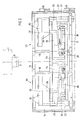
- the eroding machine comprises a base 3 on which a table 4 which is displaceable in the X and Y directions is mounted.
- the table 4 carries a trough 5 which is open at the top and serves to hold the liquid required for the eroding process.
- a column 6, which carries the machine head 7, is also attached to the base 3.
- the sleeve 8 is provided with a chuck 9 for receiving a machining tool 10, which is only indicated schematically, namely an eroding electrode.
- a workpiece holder 11 is arranged in the tub 5 and receives a workpiece 12 to be machined.
- the tub 5 is provided on its front side with a door-like front wall 14, for example by means of a coulter kidneys 15 is pivotally attached to the tub 5.
- a door-like front wall 14 On the inside of the front wall 14 there is an upper cross member 16 and a lower cross member 17, between which two guide columns 18 extend.
- a frame is provided, consisting of an upper cross-member 19, a lower cross-member 20 and a left and right-hand connecting cross member 21 in each case.
- the frame is mounted in a height-adjustable manner along the guide columns 18.
- the same for example pneumatic drive cylinders 22, are provided on both sides, which are supported at the bottom on the lower crossmember 17 and which are connected at the top to extensions of the upper crossmember 19 of the frame projecting beyond the lateral connecting crossbars 21.
- the first pair of swivel arms comprises an outer arm 23 and an inner arm 24, and the second pair of swivel arms comprises an outer arm 25 and an inner arm 26.
- the swivel arms 23-26 approximately Z-shaped shape, wherein the one outer leg of each swivel arm 23-26 is pivotally mounted about a shaft 27, which extend between the upper crossbar 19 and the lower crossbar 20 of the frame.
- the two other outer legs of the first pair of leg arms 23, 24 carry a bearing block 28 and the two other outer legs of the second pair of pivot arms carry a bearing block 29, the connection between the respective outer legs and the associated one Bearing block is also articulated. Overall, this results in a parallelogram-like linkage arrangement for parallel displacement of the bearing blocks 28 and 29.
- the two bearing blocks 28 and 29 each carry a cross bar 30 and 31, to which four electrode carriers 32 are fastened in the example. 3-5, have a tongue-like shape and protrude perpendicularly from the crossbeams 30 and 31, in the direction towards the interior of the tub 5. At their free end they are provided with a slot-like opening 33 which serves to receive the shaft 34 of an electrode 10 (FIGS. 4 and 5).
- An electrode carrier arrangement is formed by the frame, formed from the cross members 19, 20 and 21, by the four pivot arms 23, 24, 25 and 26, by the bearing blocks 28 and 29, by the crossbeams 30 and 31 and by the electrode carrier 32 which, on the one hand, is adjustable in height under the action of the drive cylinder 22 and, on the other hand, can be swung out from a rest position into an operating position.
- the pivoting movement takes place under the effect of e.g. pneumatic drive cylinders 35 which are supported at one end on the connecting cross members 21 and which are articulated at the other ends with the swivel arms 24 and 26, respectively.
- the device works as follows:
- the tub 5 is displaced in the X and / or Y direction by drive means, not shown, which are known per se, until the central axis B of the chuck 9 of the sleeve 8 coincides with the central axis C of the electrode 10.
- the entire frame 19, 20, 21 can then be moved upwards under the action of the drive cylinder 22 until the shaft 34 of the electrode 10 enters the chuck 9 and the electrode is clamped on the quill 8.
- the tub 5 in the direction Y1 (Fig. 5)
- the shaft 34 is released from the electrode support 32, the frame 19, 20, 21 can be lowered again and the pivot arms 23, 24 can be pivoted back into the rest position.
- the eroding process can now begin by means of the first, just clamped-in electrode 10.
- the pivoted-back carrier units 36 and 37 do not hinder this, since the electrodes 10 held in stock in the electrode carriers 32 lie very close to the front wall 14 (FIG. 4).
- the first carrier unit 36 is pivoted out again and raised and finally brought into such a position by moving the tub 5 in the X and Y2 direction that the electrode carrier 32 in question Pinole 8 has clamped clamped electrode 10 on the shaft 34.
- the frame 19, 20, 21 is lowered or the quill 8 is raised, the trough 5 is displaced in the X direction until the central axis C of the next required electrode 10 is aligned with the central axis B of the quill 8, and again Raising the frame 19, 20, 21 or lowering the quill 8 in order to insert this next electrode 10.
- the tub 5 is moved again in the previously described manner in the Y 1 direction, the frame is lowered if necessary and the swivel arms 23, 24 are pivoted back so that the subsequent erosion step can take place.
- This process is repeated in an analogous manner, including a plurality of electrodes, until the erosive machining of the workpiece 12 has ended. If, in the example, all four electrodes 10 have been used in the first carrier unit 26, the second carrier unit 37 is of course subsequently pivoted in. Due to the design and arrangement of the swivel arms 23, 24 and 25, 26, the respective crossbar 30 and 31 with the associated electrode carriers 32 is in both cases at the same, central position within the tub 5, which minimizes the required displacement movements and the control of the machine is considerably simplified. In the interest of optimizing the motion sequences, it is advisable to enter the electrodes in a sensible arrangement in the electrode carriers 32, for example the first four required electrodes in the unit 36 and the next four required electrodes in the unit 37.
- the crossbeams 30 and 31 can be detachably and interchangeably fastened to the bearing blocks 28 and 29 in order to optionally have a group of four electrode carriers which are relatively far apart 32 for comparatively large electrodes 10 (as shown in the drawings) or a group of maybe five or six electrode carriers 32 closer together for smaller electrodes.
- the design and arrangement of the frame 19, 20, 21 and the swivel arms 23, 24, 25, 26 can also be different, as long as the swivel movement of the electrode carrier required according to the invention changes from a rest position near the tub wall to an operating position in an approximately central position within the tub can be realized.
- the device proposed according to the invention creates a handling device for electrodes which is very simple in construction, robust and uncomplicated and inexpensive to manufacture. It may be sufficient for numerous applications in which it is not required to keep a large number of electrodes ready for access, but in which only a few electrodes have to be replaced. Since most of the die sinking EDM machines on the market are equipped with a trough, the front wall of which can be swung out like a door, the design of the proposed device, in which the entire electrode carrier arrangement is anchored to the front wall, is practically for retrofitting existing machines. Because the required movement sequences within the device are very simple (pivoting of the arms and height adjustment of the frame), a fully automatic electrode change can be very easily integrated into an existing machine program with the aid of the device according to the invention.
Landscapes
- Engineering & Computer Science (AREA)
- Mechanical Engineering (AREA)
- Chemical & Material Sciences (AREA)
- Chemical Kinetics & Catalysis (AREA)
- Electrochemistry (AREA)
- Electrical Discharge Machining, Electrochemical Machining, And Combined Machining (AREA)
- Manipulator (AREA)
Priority Applications (1)
| Application Number | Priority Date | Filing Date | Title |
|---|---|---|---|
| AT88810423T ATE74811T1 (de) | 1987-07-03 | 1988-06-21 | Vorrichtung zur handhabung von elektroden an einer senkerodiermaschine. |
Applications Claiming Priority (2)
| Application Number | Priority Date | Filing Date | Title |
|---|---|---|---|
| DE3722032A DE3722032C1 (de) | 1987-07-03 | 1987-07-03 | Vorrichtung zur Handhabung von Elektroden an einer Senkerodiermaschine |
| DE3722032 | 1987-07-03 |
Publications (3)
| Publication Number | Publication Date |
|---|---|
| EP0298028A2 EP0298028A2 (de) | 1989-01-04 |
| EP0298028A3 EP0298028A3 (en) | 1989-04-26 |
| EP0298028B1 true EP0298028B1 (de) | 1992-04-15 |
Family
ID=6330858
Family Applications (1)
| Application Number | Title | Priority Date | Filing Date |
|---|---|---|---|
| EP88810423A Expired - Lifetime EP0298028B1 (de) | 1987-07-03 | 1988-06-21 | Vorrichtung zur Handhabung von Elektroden an einer Senkerodiermaschine |
Country Status (11)
| Country | Link |
|---|---|
| US (1) | US4853512A (cg-RX-API-DMAC7.html) |
| EP (1) | EP0298028B1 (cg-RX-API-DMAC7.html) |
| JP (1) | JPH074700B2 (cg-RX-API-DMAC7.html) |
| KR (1) | KR950015118B1 (cg-RX-API-DMAC7.html) |
| AT (1) | ATE74811T1 (cg-RX-API-DMAC7.html) |
| CA (1) | CA1303145C (cg-RX-API-DMAC7.html) |
| DE (2) | DE3722032C1 (cg-RX-API-DMAC7.html) |
| ES (1) | ES2030528T3 (cg-RX-API-DMAC7.html) |
| GR (1) | GR3004478T3 (cg-RX-API-DMAC7.html) |
| HK (1) | HK13893A (cg-RX-API-DMAC7.html) |
| SG (1) | SG100992G (cg-RX-API-DMAC7.html) |
Families Citing this family (9)
| Publication number | Priority date | Publication date | Assignee | Title |
|---|---|---|---|---|
| US5785838A (en) * | 1993-02-26 | 1998-07-28 | Nikon Corporation By Hiroyuki Sugimura | Method for producing an oxide film |
| DE4330885C1 (de) * | 1993-09-13 | 1995-02-09 | Knecht Hans | Funkenerosionsmaschine |
| JP3393748B2 (ja) * | 1996-02-06 | 2003-04-07 | ファナック株式会社 | 放電加工機 |
| DE19726664A1 (de) * | 1997-06-23 | 1998-12-24 | 3R Syst Int Ab | Linearer Werkzeugwechsler |
| US6326576B1 (en) | 1999-09-22 | 2001-12-04 | General Electric Company | Method and apparatus for electrical discharge machining |
| US6369343B1 (en) | 2000-09-20 | 2002-04-09 | General Electric Company | Method and apparatus for electrical discharge machining |
| US6720516B2 (en) * | 2000-12-12 | 2004-04-13 | Matsushita Electric Industrial Co., Ltd. | apparatus for electric discharge micromachining of a micro-diameter hole |
| FR2951390B1 (fr) * | 2009-10-20 | 2012-01-06 | Areva Nc | Dispositif de changement d'electrode a securite amelioree |
| EP4378614A1 (en) * | 2022-12-01 | 2024-06-05 | Agie Charmilles SA | A tool changer for an electrical discharge machine tool and the electrical discharge machine tool |
Family Cites Families (10)
| Publication number | Priority date | Publication date | Assignee | Title |
|---|---|---|---|---|
| DE2837719C2 (de) * | 1978-08-30 | 1982-11-04 | Aeg-Elotherm Gmbh, 5630 Remscheid | Funkenerosionsmaschine mit einer Einrichtung zum selbsttätigen Wechsel ihrer Bearbeitungselektrode |
| CH627109A5 (cg-RX-API-DMAC7.html) * | 1979-03-09 | 1981-12-31 | Charmilles Sa Ateliers | |
| DE3035215A1 (de) * | 1980-09-18 | 1982-05-06 | Dieter Hansen GmbH, 6116 Eppertshausen | Werkzeugwechseleinrichtung fuer eine werkzeugmaschine |
| CH649021A5 (fr) * | 1982-08-06 | 1985-04-30 | Charmilles Sa Ateliers | Machine a usiner par decharges electriques erosives. |
| DE3300017A1 (de) * | 1983-01-03 | 1984-07-12 | Alb. Klein Gmbh & Co Kg, 5241 Niederfischbach | Flachkammer-waermetauscher sowie verfahren und vorrichtung zu dessen herstellung |
| DE3303758A1 (de) * | 1983-02-04 | 1984-08-09 | Schiess Ag | Funkenerosionsmaschine |
| EP0132599A1 (de) * | 1983-07-06 | 1985-02-13 | Charmilles Technologies Sa | Werkzeugmagazin mit Werkzeug-Wechselvorrichtung |
| JPH0767441B2 (ja) * | 1985-07-30 | 1995-07-26 | 株式会社東芝 | 磁気共鳴イメ−ジング装置 |
| DE3533001A1 (de) * | 1985-09-16 | 1987-03-26 | Agie Ag Ind Elektronik | Verfahren zum aufspannen von werkzeugen und/oder werkstuecken an einer werkzeugmaschine und spannvorrichtung zur durchfuehrung des verfahrens |
| DE3533002A1 (de) * | 1985-09-16 | 1987-03-26 | Agie Ag Ind Elektronik | Elektroerosionsverfahren und elektroerosionsmaschine zur durchfuehrung des verfahrens |
-
1987
- 1987-07-03 DE DE3722032A patent/DE3722032C1/de not_active Expired
-
1988
- 1988-06-21 ES ES198888810423T patent/ES2030528T3/es not_active Expired - Lifetime
- 1988-06-21 DE DE8888810423T patent/DE3870054D1/de not_active Expired - Lifetime
- 1988-06-21 AT AT88810423T patent/ATE74811T1/de not_active IP Right Cessation
- 1988-06-21 EP EP88810423A patent/EP0298028B1/de not_active Expired - Lifetime
- 1988-06-30 CA CA000570952A patent/CA1303145C/en not_active Expired - Lifetime
- 1988-06-30 JP JP63164073A patent/JPH074700B2/ja not_active Expired - Lifetime
- 1988-07-01 US US07/214,314 patent/US4853512A/en not_active Expired - Fee Related
- 1988-07-02 KR KR1019880008261A patent/KR950015118B1/ko not_active Expired - Fee Related
-
1992
- 1992-04-30 GR GR920400835T patent/GR3004478T3/el unknown
- 1992-10-05 SG SG1009/92A patent/SG100992G/en unknown
-
1993
- 1993-02-18 HK HK138/93A patent/HK13893A/xx not_active IP Right Cessation
Also Published As
| Publication number | Publication date |
|---|---|
| SG100992G (en) | 1992-12-04 |
| DE3870054D1 (de) | 1992-05-21 |
| EP0298028A2 (de) | 1989-01-04 |
| ES2030528T3 (es) | 1992-11-01 |
| GR3004478T3 (cg-RX-API-DMAC7.html) | 1993-03-31 |
| JPH074700B2 (ja) | 1995-01-25 |
| DE3722032C1 (de) | 1988-09-29 |
| KR950015118B1 (ko) | 1995-12-22 |
| CA1303145C (en) | 1992-06-09 |
| KR890001673A (ko) | 1989-03-28 |
| US4853512A (en) | 1989-08-01 |
| HK13893A (en) | 1993-02-26 |
| JPS6420933A (en) | 1989-01-24 |
| EP0298028A3 (en) | 1989-04-26 |
| ATE74811T1 (de) | 1992-05-15 |
Similar Documents
| Publication | Publication Date | Title |
|---|---|---|
| DE3720180C1 (de) | Wechselvorrichtung fuer eine Werkzeugmaschine | |
| DE3427245C2 (de) | Werkzeugmaschine | |
| DE2839978C2 (cg-RX-API-DMAC7.html) | ||
| EP0128487B1 (de) | Werkzeugmaschine mit einem stationären Magazin | |
| DE3533235C2 (de) | Biegepresse | |
| EP0607793A1 (de) | Rundtakt-Werkzeugmaschine | |
| EP0562216A1 (de) | Maschine zum Bearbeiten von Werkstücken | |
| EP1016497A2 (de) | Werkzeugmaschine | |
| DE3440224C2 (de) | Werkzeugwechselvorrichtung an einer Stanz- oder Nibbelmaschine | |
| DE69602164T2 (de) | Automatische bohr- und fräsmaschine für glassplatten | |
| EP0298028B1 (de) | Vorrichtung zur Handhabung von Elektroden an einer Senkerodiermaschine | |
| DE3590391T (de) | Einrichtung zum Stanzen mittels Stanzstegen | |
| DE19843889A1 (de) | Stanzwerkzeug-Speicher-und Wechselsystem | |
| EP1927429A1 (de) | Werkzeugmaschine mit Werkzeugmagazin | |
| EP3849741B1 (de) | Werkzeugmaschine | |
| DE3829105C2 (cg-RX-API-DMAC7.html) | ||
| EP1651381B1 (de) | Werkzeugmaschine mit einspannvorrichtung auf beiden seiten | |
| DE10235518B4 (de) | Verfahren und Vorrichtung zur Werkstück-Bearbeitung | |
| DE10011861B4 (de) | Maschine zum Bearbeiten von Hohlglasgegenständen | |
| DE2935523A1 (de) | Werkzeugmaschine mit automatischem werkzeugwechsel | |
| EP0142749A2 (de) | Werkzeugwechseleinrichtung für eine Vielspindelwerkzeugmaschine | |
| EP0811460A1 (de) | Werkzeugmaschine | |
| DE3322877A1 (de) | Bearbeitungszentrum fuer fraes- und bohrarbeiten | |
| DE3239482C2 (cg-RX-API-DMAC7.html) | ||
| CH665159A5 (de) | Schleifmaschine. |
Legal Events
| Date | Code | Title | Description |
|---|---|---|---|
| PUAI | Public reference made under article 153(3) epc to a published international application that has entered the european phase |
Free format text: ORIGINAL CODE: 0009012 |
|
| AK | Designated contracting states |
Kind code of ref document: A2 Designated state(s): AT BE CH DE ES FR GB GR IT LI LU NL SE |
|
| PUAL | Search report despatched |
Free format text: ORIGINAL CODE: 0009013 |
|
| AK | Designated contracting states |
Kind code of ref document: A3 Designated state(s): AT BE CH DE ES FR GB GR IT LI LU NL SE |
|
| 17P | Request for examination filed |
Effective date: 19890616 |
|
| 17Q | First examination report despatched |
Effective date: 19910123 |
|
| GRAA | (expected) grant |
Free format text: ORIGINAL CODE: 0009210 |
|
| AK | Designated contracting states |
Kind code of ref document: B1 Designated state(s): AT BE CH DE ES FR GB GR IT LI LU NL SE |
|
| REF | Corresponds to: |
Ref document number: 74811 Country of ref document: AT Date of ref document: 19920515 Kind code of ref document: T |
|
| REF | Corresponds to: |
Ref document number: 3870054 Country of ref document: DE Date of ref document: 19920521 |
|
| GBT | Gb: translation of ep patent filed (gb section 77(6)(a)/1977) | ||
| ET | Fr: translation filed | ||
| ITF | It: translation for a ep patent filed | ||
| REG | Reference to a national code |
Ref country code: ES Ref legal event code: FG2A Ref document number: 2030528 Country of ref document: ES Kind code of ref document: T3 |
|
| REG | Reference to a national code |
Ref country code: GR Ref legal event code: FG4A Free format text: 3004478 |
|
| PLBE | No opposition filed within time limit |
Free format text: ORIGINAL CODE: 0009261 |
|
| STAA | Information on the status of an ep patent application or granted ep patent |
Free format text: STATUS: NO OPPOSITION FILED WITHIN TIME LIMIT |
|
| 26N | No opposition filed | ||
| EPTA | Lu: last paid annual fee | ||
| EAL | Se: european patent in force in sweden |
Ref document number: 88810423.9 |
|
| PGFP | Annual fee paid to national office [announced via postgrant information from national office to epo] |
Ref country code: FR Payment date: 19960510 Year of fee payment: 9 |
|
| PGFP | Annual fee paid to national office [announced via postgrant information from national office to epo] |
Ref country code: AT Payment date: 19960517 Year of fee payment: 9 |
|
| PGFP | Annual fee paid to national office [announced via postgrant information from national office to epo] |
Ref country code: SE Payment date: 19960520 Year of fee payment: 9 Ref country code: BE Payment date: 19960520 Year of fee payment: 9 |
|
| PGFP | Annual fee paid to national office [announced via postgrant information from national office to epo] |
Ref country code: GB Payment date: 19960521 Year of fee payment: 9 |
|
| PGFP | Annual fee paid to national office [announced via postgrant information from national office to epo] |
Ref country code: GR Payment date: 19960522 Year of fee payment: 9 |
|
| PGFP | Annual fee paid to national office [announced via postgrant information from national office to epo] |
Ref country code: DE Payment date: 19960528 Year of fee payment: 9 |
|
| PGFP | Annual fee paid to national office [announced via postgrant information from national office to epo] |
Ref country code: NL Payment date: 19960529 Year of fee payment: 9 |
|
| PGFP | Annual fee paid to national office [announced via postgrant information from national office to epo] |
Ref country code: LU Payment date: 19960601 Year of fee payment: 9 |
|
| PGFP | Annual fee paid to national office [announced via postgrant information from national office to epo] |
Ref country code: CH Payment date: 19960606 Year of fee payment: 9 |
|
| PGFP | Annual fee paid to national office [announced via postgrant information from national office to epo] |
Ref country code: ES Payment date: 19960613 Year of fee payment: 9 |
|
| PG25 | Lapsed in a contracting state [announced via postgrant information from national office to epo] |
Ref country code: LU Free format text: LAPSE BECAUSE OF NON-PAYMENT OF DUE FEES Effective date: 19970621 Ref country code: GB Free format text: LAPSE BECAUSE OF NON-PAYMENT OF DUE FEES Effective date: 19970621 Ref country code: AT Effective date: 19970621 |
|
| PG25 | Lapsed in a contracting state [announced via postgrant information from national office to epo] |
Ref country code: SE Effective date: 19970622 |
|
| PG25 | Lapsed in a contracting state [announced via postgrant information from national office to epo] |
Ref country code: ES Free format text: LAPSE BECAUSE OF NON-PAYMENT OF DUE FEES Effective date: 19970623 |
|
| PG25 | Lapsed in a contracting state [announced via postgrant information from national office to epo] |
Ref country code: LI Free format text: LAPSE BECAUSE OF NON-PAYMENT OF DUE FEES Effective date: 19970630 Ref country code: GR Free format text: LAPSE BECAUSE OF NON-PAYMENT OF DUE FEES Effective date: 19970630 Ref country code: CH Free format text: LAPSE BECAUSE OF NON-PAYMENT OF DUE FEES Effective date: 19970630 Ref country code: BE Effective date: 19970630 |
|
| BERE | Be: lapsed |
Owner name: EROWA A.G. Effective date: 19970630 |
|
| PG25 | Lapsed in a contracting state [announced via postgrant information from national office to epo] |
Ref country code: NL Effective date: 19980101 |
|
| GBPC | Gb: european patent ceased through non-payment of renewal fee |
Effective date: 19970621 |
|
| REG | Reference to a national code |
Ref country code: CH Ref legal event code: PL |
|
| PG25 | Lapsed in a contracting state [announced via postgrant information from national office to epo] |
Ref country code: FR Free format text: LAPSE BECAUSE OF NON-PAYMENT OF DUE FEES Effective date: 19980227 |
|
| EUG | Se: european patent has lapsed |
Ref document number: 88810423.9 |
|
| NLV4 | Nl: lapsed or anulled due to non-payment of the annual fee |
Effective date: 19980101 |
|
| PG25 | Lapsed in a contracting state [announced via postgrant information from national office to epo] |
Ref country code: DE Free format text: LAPSE BECAUSE OF NON-PAYMENT OF DUE FEES Effective date: 19980303 |
|
| REG | Reference to a national code |
Ref country code: FR Ref legal event code: ST |
|
| REG | Reference to a national code |
Ref country code: FR Ref legal event code: ST |
|
| REG | Reference to a national code |
Ref country code: ES Ref legal event code: FD2A Effective date: 20000403 |
|
| PG25 | Lapsed in a contracting state [announced via postgrant information from national office to epo] |
Ref country code: IT Free format text: LAPSE BECAUSE OF NON-PAYMENT OF DUE FEES;WARNING: LAPSES OF ITALIAN PATENTS WITH EFFECTIVE DATE BEFORE 2007 MAY HAVE OCCURRED AT ANY TIME BEFORE 2007. THE CORRECT EFFECTIVE DATE MAY BE DIFFERENT FROM THE ONE RECORDED. Effective date: 20050621 |