EP0297493A2 - Protecting device for pipe ends - Google Patents
Protecting device for pipe ends Download PDFInfo
- Publication number
- EP0297493A2 EP0297493A2 EP88110251A EP88110251A EP0297493A2 EP 0297493 A2 EP0297493 A2 EP 0297493A2 EP 88110251 A EP88110251 A EP 88110251A EP 88110251 A EP88110251 A EP 88110251A EP 0297493 A2 EP0297493 A2 EP 0297493A2
- Authority
- EP
- European Patent Office
- Prior art keywords
- insert
- protection device
- circumferential
- cover
- metal
- Prior art date
- Legal status (The legal status is an assumption and is not a legal conclusion. Google has not performed a legal analysis and makes no representation as to the accuracy of the status listed.)
- Granted
Links
Images


Classifications
-
- B—PERFORMING OPERATIONS; TRANSPORTING
- B65—CONVEYING; PACKING; STORING; HANDLING THIN OR FILAMENTARY MATERIAL
- B65D—CONTAINERS FOR STORAGE OR TRANSPORT OF ARTICLES OR MATERIALS, e.g. BAGS, BARRELS, BOTTLES, BOXES, CANS, CARTONS, CRATES, DRUMS, JARS, TANKS, HOPPERS, FORWARDING CONTAINERS; ACCESSORIES, CLOSURES, OR FITTINGS THEREFOR; PACKAGING ELEMENTS; PACKAGES
- B65D59/00—Plugs, sleeves, caps, or like rigid or semi-rigid elements for protecting parts of articles or for bundling articles, e.g. protectors for screw-threads, end caps for tubes or for bundling rod-shaped articles
- B65D59/06—Caps
-
- F—MECHANICAL ENGINEERING; LIGHTING; HEATING; WEAPONS; BLASTING
- F16—ENGINEERING ELEMENTS AND UNITS; GENERAL MEASURES FOR PRODUCING AND MAINTAINING EFFECTIVE FUNCTIONING OF MACHINES OR INSTALLATIONS; THERMAL INSULATION IN GENERAL
- F16L—PIPES; JOINTS OR FITTINGS FOR PIPES; SUPPORTS FOR PIPES, CABLES OR PROTECTIVE TUBING; MEANS FOR THERMAL INSULATION IN GENERAL
- F16L57/00—Protection of pipes or objects of similar shape against external or internal damage or wear
- F16L57/005—Protection of pipes or objects of similar shape against external or internal damage or wear specially adapted for the ends of pipes
Definitions
- the invention relates to a protective device for pipe ends according to the preamble of claim 1.
- Protective devices with one-piece inserts or covers as well as protective devices which consist only of plastic also have the disadvantage that they are difficult to dismantle at low temperatures due to the contraction of the plastic and are even more difficult to assemble. This can occur when using such protective devices, e.g. B. on oil pipes, which are used at very different temperatures, lead to considerable problems, in particular when used on large diameter pipes.
- the object of the present invention is therefore to design a protective device of the type mentioned at the outset in such a way that greater stability can be achieved. Furthermore, the production should be facilitated.
- Protective devices of the type specified in claim 1 and dependent claim 2 have a considerably higher stability than the previously known protective devices, namely by the flanged or folded or rolled edge.
- the metal housing designed according to the invention and the metal plug designed according to the invention are the same advantageous, can be used for both one-piece and multi-piece inserts and covers.
- the grooves designed in use can be used, for example, for inserting a base in order to make a closed protective cap from an open protective cap.
- Separate sealing elements can also be inserted into the grooves, as can be gathered from claim 9.
- molded thin-walled webs can also be provided as axial sealing rings.
- the development according to claim 10 enables the insertion of a rod-shaped auxiliary tool for assembling and disassembling the protective devices.
- the bent tongues serve to reinforce the attachment surfaces of the auxiliary tool and at the same time act as drivers for the plastic insert, since they lie against the lateral boundaries of the insert or the cover.
- FIGS. 1 to 5 and 10 an insert 2 consisting of two halves 4, 6 for a metal housing 8 according to FIGS. 6 to 9 and 11.
- Each half of the insert is semi-cylindrical and has a thickened end on the end face 10 on.
- a thread 12 is formed on the inner surface.
- a circumferential circumferential groove 14 can be formed on the outer surface.
- Each insert half has two contact surfaces 16, 18 and 16 ', 18', of which only one can be seen in FIGS. 1 to 5, which is provided with the reference numerals 16 and 16 '.
- the contact surfaces of one insert half 4 have a groove 20 and the contact surfaces of the other insert half have a tongue 22 complementary to the groove.
- One contact surface of the insert halves 4 and 6 can also be provided with a groove and the other contact surface with a corresponding tongue.
- the tongue and the groove have a radially inward bend or bend 24.
- the insert halves 4 and 6 according to FIGS. 1 and 2 also have a groove 26 on the inside in the region of the thickened end 10.
- the groove 26 forms a circumferential inner annular groove into which, for example, a plastic cover 28 can be inserted, in order to form a closed protective cap, as is shown in FIG. 3.
- the lid can also have a pot shape 30, as shown in FIG. 4.
- FIG. 5 shows an embodiment in which a lip seal 30 is inserted into the groove 26 and has a lip 36 which projects beyond the sealing gap 32 between a tube 34 and the insert 2.
- the thickened end of the end face of the insert halves is each provided with a rectangular recess 38, 38 '. This can be seen particularly clearly in FIG. 10, which shows the two insert halves 4 and 6 in the assembled state.
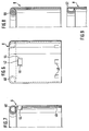
- FIGS. 6 to 9 and 11, show different embodiments of the metal housing 8.
- 6 shows a metal housing, the outer end edge of which is provided with an inwardly directed rolling edge 40.
- the cylindrical metal housing 8 has two diametrically opposite openings 42, 42 'with two lateral inwardly bent tongues 44, 46, as can be seen particularly clearly in FIGS. 7 and 11.
- the tongues 44 and 46 engage in the recesses 38, 38 ', whereby a locking is achieved in the circumferential direction.
- a rod-shaped tool can be inserted through the openings 42, 42 'and the recesses 38, 38' during assembly and disassembly of the protective device.
- the metal housing has inwardly distributed tongues 48 which engage in the circumferential groove 14 of the insert 2 and thereby bring about an axial fixation.
- the rolled edge is formed in a spiral shape 50, wherein the spiral can also be formed so far that the spiral cavity is completely filled.
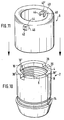
- a hollow cylindrical metal plug 54 is shown, which has an outwardly directed rolling edge 56 at its outer front end.
- the metal plug 50 is surrounded by coating halves, which are not shown, but are designed quite analogously to the insert halves 4 and 6 according to FIGS. 1 to 5.
- the metal plug 54 has two diametrically opposite openings 58 with lateral outwardly directed tongues 60, 62 , see. also Fig. 13. These tongues 60, 62 engage in corresponding recesses of the coating, not shown, in a manner analogous to that of the metal housing 8.
- FIG. 14 and 15 show two further embodiments of the metal stopper, the rolled edge being designed in the form of a spiral 64 in the embodiment according to FIG. 14 and in the form of an oval 66 in the embodiment according to FIG. 15.
- the insert 2 can have a circumferential groove for an O-ring 72 on the inside at this end, which in the Fig. 4 is shown in dashed lines for the insert half 6, or have a circumferential, molded, tapered sealing web 74 on the inside at this end 68, which is shown in dashed lines in FIG. 3 for the one insert half 6.
- cover of a protective plug can have a groove on the outside for an O-ring or a molded, circumferential sealing web, which is not shown in the drawing.
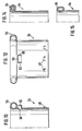
- FIG. 16 shows, in section, a protective cap 80 which has a hollow cylindrical metal housing 82 with a sleeve-shaped insert 84 made of elastomeric material which lies tightly against the metal housing.
- the metal cylinder 82 has an inwardly bent flanged edge 86 at the outer end.
- the insert 84 protrudes into the flanging of the flanged edge 86 in such a way that the inwardly bent part of the flanged edge overlaps the end of the insert and the free flanged edge 88 engages in the insert or is clamped against the insert.
- the insert 84 has a circumferential stop 90 for the tube end 92, an intermediate space 94 being left in the manner of a groove between the stop 90 and the flanged edge 86 of the metal housing 82, into which an elastic cover 96 can be snapped out again.
- the stop 90 like the embodiment according to FIG. 5, has a circumferential seal 30 to cover the sealing gap 32 between the stop and the pipe end 92.
- FIG. 17 shows in section a protective plug 100 which has a hollow cylindrical metal plug 102 with a sleeve-shaped coating 104 made of elastomeric material.
- the hollow cylindrical metal plug has a flanged edge 106 which is bent outwards at the end.
- the cover 104 protrudes into the flanging of the flanged edge 106 in such a way that the outwardly bent part of the flanged edge overlaps the end of the cover 104 and the free flanged edge 107 engages in the cover or is clamped against the cover.
- the cover 104 has a circumferential stop 108 for the pipe end 100.
- the metal stopper has a circumferential recess or a plurality of spaced recesses 112 on the inside in the region of the flanged edge 106, into which an elastic cover 114 with a circumferential rib or with a plurality of spaced projections 116 can be snapped out again.
- a circumferential seal 118 On the ring-shaped pipe stop surface of the An Impact 108 is formed to cover the gap between the stop and the pipe end, a circumferential seal 118 in the form of a sealing lip, which in the unloaded state shows obliquely outwards (shown in dashed lines). However, there can also be a groove 120 (shown in broken lines) for an insertable seal.
Abstract
Description
Die Erfindung betrifft eine Schutzvorrichtung für Rohrenden gemäß Oberbegriff des Anspruchs 1.The invention relates to a protective device for pipe ends according to the preamble of claim 1.
Schutzvorrichtungen, die aus einem Metallgehäuse und einem einteiligen Kunststoffeinsatz bestehen oder aus einem Metallstopfen und einem einteiligen hülsenförmigen Überzug, sind seit langem bekannt, vgl. DE-PS 29 39 384 und DE-OS 28 00 747. Nachteilig ist, daß die Einsätze und Überzüge mit relativ aufwendigen Werkzeugen hergestellt werden müssen, bei denen entweder nach dem Spritzen der Gewindekern herausgeschraubt oder der Einsatz bzw. Überzug vom Kern abgeschraubt werden muß. Werkzeuge mit sogenannten Fallkernen sind wegen des komplizierten Aufbaues nur zur Herstellung von Vorrichtungen hoher Stückzahlen wirtschaftlich einsetzbar.Protective devices which consist of a metal housing and a one-piece plastic insert or of a metal plug and a one-piece sleeve-shaped coating have long been known, cf. DE-PS 29 39 384 and DE-OS 28 00 747. It is disadvantageous that the inserts and covers have to be produced with relatively complex tools, in which either screwed out after the thread core has been sprayed or the insert or cover has to be unscrewed from the core . Because of their complicated structure, tools with so-called drop cores can only be used economically for the production of devices in large numbers.
Ferner sind auch nur aus Kunststoff bestehende Schutzvorrichtungen seit langem bekannt.Furthermore, protective devices consisting only of plastic have also been known for a long time.
Schutzvorrichtungen mit einteiligen Einsätzen oder Überzügen sowie Schutzvorrichtungen, die nur aus Kunststoff bestehen, haben ferner den Nachteil, daß sie bei tiefen Temperaturen infolge des Zusammenziehens des Kunststoffes schwer zu demontieren und noch schwerer zu montieren sind. Das kann beim Gebrauch solcher Schutzvorrichtungen, z. B. an Erdölrohren, die bei sehr unterschiedlichen Temperaturen benutzt werden, zu erheblichen Problemen führen, insbesondere bei der Verwendung an Rohren mit großem Durchmesser.Protective devices with one-piece inserts or covers as well as protective devices which consist only of plastic also have the disadvantage that they are difficult to dismantle at low temperatures due to the contraction of the plastic and are even more difficult to assemble. This can occur when using such protective devices, e.g. B. on oil pipes, which are used at very different temperatures, lead to considerable problems, in particular when used on large diameter pipes.
Bekannt sind auch Schutzvorrichtungen,bei denen das Metallgehäuse oder der Metallstopfen am oberen Rand einfach umgebogen ist, um den Schutzkappen bzw. Schutzstopfen eine höhere Stabilität zu geben. In vielen Fällen, insbesondere bei Rohren mit großem Durchmesser bzw. bei sehr schweren Rohren, reicht die Stabilität aber nicht aus, um das Rohrende und das Gewinde des Rohres gegen Schlagbeanspruchung wirksam zu schützenProtective devices are also known in which the metal housing or the metal plug is simply bent over at the upper edge in order to give the protective caps or protective plugs greater stability. In many cases, especially with pipes with a large diameter or with very heavy pipes, the stability is not sufficient to effectively protect the pipe end and the thread of the pipe against impact stress
Die Aufgabe der vorliegenden Erfindung besteht deshalb darin, eine Schutzvorrichtung der eingangs genannten Art so auszubilden, daß eine höhere Stabilität erreichbar ist. Ferner soll die Herstellung erleichteret werden.The object of the present invention is therefore to design a protective device of the type mentioned at the outset in such a way that greater stability can be achieved. Furthermore, the production should be facilitated.
Die Aufgabe wird durch die Ausbildung gemäß Kennzeichen des Anspruchs 1 gelöst. Die Herstellung wird wesentlich erleichtert durch die Ausbildungen nach den Ansprüchen 3 bis 6. Vorteilhafte und zweckmäßige Weiterbildungen sind in den weiteren Ansprüchen angegeben.The object is achieved by the training according to the characterizing part of claim 1. The manufacture is considerably facilitated by the training according to claims 3 to 6. Advantageous and expedient further developments are specified in the further claims.
Schutzvorrichtungen der im Anspruch 1 und dem Unteranspruch 2 angegebenen Art weisen eine erheblich höhere Stabilität als die bisher bekannten Schutzvorrichtungen auf, und zwar durch den gebördelten oder gefalzten bzw. gerollten Rand.Protective devices of the type specified in claim 1 and dependent claim 2 have a considerably higher stability than the previously known protective devices, namely by the flanged or folded or rolled edge.
Aufgrund der Ausbildung nach den Ansprüchen 6 bis 9 ist die Herstellung des Einsatzes bzw. des Überzuges mit einfachen Werkzeugen möglich, die wesentlich billiger herzustellen sind als die bisher im Stand der Technik eingesetzten Werkzeuge. Die Werkzeuge brauchen einfach nur mit Auswerferstiften versehen zu werden, um die Spritzgußform zu entformen. Hierdurch kann die Kühlzeit und die Herstellzeit wesentlich verkürzt werden.Due to the design according to
Das erfindungsgemäß ausgebildete Metallgehäuse und der erfindungsgemäß ausgebildete Metallstopfen sind gleichermaßen vorteilhaft, sowohl bei einteiligen als auch bei mehrteiligen Einsätzen und Überzügen einsetzbar.The metal housing designed according to the invention and the metal plug designed according to the invention are the same advantageous, can be used for both one-piece and multi-piece inserts and covers.
Die im Einsatz ausgebildeten Nuten können beispielsweise zum Einlegen eines Bodens verwendet werden, um aus einer offenen Schutzkappe eine geschlossene Schutzkappe zu machen. In die Nuten können auch separate Dichtungselemente eingelegt werden, wie dies dem Anspruch 9 zu entnehmen ist. Anstelle solcher Dichtungselemente können auch angespritzte dünnwandige Stege als Axialdichtringe vorgesehen werden.The grooves designed in use can be used, for example, for inserting a base in order to make a closed protective cap from an open protective cap. Separate sealing elements can also be inserted into the grooves, as can be gathered from claim 9. Instead of such sealing elements, molded thin-walled webs can also be provided as axial sealing rings.
Die Weiterbildung gemäß Anspruch 10 ermöglicht das Durchstecken eines stabförmigen Hilfswerkzeuges zum Montieren und Demontieren der Schutzvorrichtungen. Die ausgebogenen Zungen dienen dabei als Verstärkung der Ansatzflächen des Hilfswerkzeuges und fungieren gleichzeitig als Mitnehmer für den Kunststoffeinsatz, da sie an den seitlichen Begrenzungen des Einsatzes bzw. des Überzuges anliegen.The development according to
Durch die Weiterbildung gemäß Anspruch 11 ist eine besonders gute Fixierung des Einsatzes bzw. des Überzuges am Metallkörper in axialer Richtung erreichbar.Through the development according to claim 11, a particularly good fixation of the insert or the coating on the metal body can be achieved in the axial direction.
Besonders vorteilhaft sind auch die Vorrichtungen nach den Ansprüchen 14 und 15.The devices according to
Die Erfindung soll nachfolgend anhand der beigefügten Zeichnung, in der Ausführungsbeispiele dargestellt sind, näher erläutert werden.The invention will be explained in more detail below with reference to the accompanying drawing, in which exemplary embodiments are shown.
Es zeigt:
- Fig. 1 eine erste Ausführungsform eines zweiteiligen Einsatzes einer erfindungsgemäßen Schutzvorrichtung,
- Fig. 2 eine Draufsicht auf eine der beiden Anlageflächen einer Hälfte des Einsatzes nach Fig. 1,
- Fig. 3 eine zweite Ausführungsform eines erfin dungsgemäßen Einsatzes,
- Fig. 4 eine dritte Ausführungsform eines erfindungsgemäßen Einsatzes,
- Fig. 5 eine vierte Ausführungsform,
- Fig. 6 eine schematische Darstellung einer ersten Ausführungsform eines Metallgehäuses der erfindungsgemäßen Schutzvorrichtung,
- Fig. 7 einen Axialschnitt durch das Metallgehäuse nach Fig. 6,
- Fig. 8 eine zweite Ausführungsform eines Metallgehäuses,
- Fig. 9 eine dritte Ausführungsform eines Metallgehäuses,
- Fig. 10 eine perspektivische Ansicht eines aus zwei Hälften zusammengesetzten Einsatzes,
- Fig. 11 eine perspektivische Darstellung eines über den Einsatz nach Fig. 10 stülpbaren Metallgehäuses,
- Fig. 12 ein erstes Ausführungsbeispiel eines zylindrischen Metallstopfens einer erfindungsgemäßen Schutzvorrichtung,
- Fig. 13 einen Schnitt durch den Metallstopfen nach Fig. 12,
- Fig. 14 eine zweite Ausführungsform eines Metallstopfens,
- Fig. 15 eine dritte Ausführungsform eines Metallstopfens,
- Fig. 16 eine weitere Ausführungsform einer Schutzkappe und
- Fig. 17 eine weitere Ausführungsform eines Schutzstopfens.
- 1 shows a first embodiment of a two-part insert of a protective device according to the invention,
- 2 shows a plan view of one of the two contact surfaces of one half of the insert according to FIG. 1,
- Fig. 3 shows a second embodiment of an invent appropriate use,
- 4 shows a third embodiment of an insert according to the invention,
- 5 shows a fourth embodiment,
- 6 shows a schematic illustration of a first embodiment of a metal housing of the protective device according to the invention,
- 7 shows an axial section through the metal housing according to FIG. 6,
- 8 shows a second embodiment of a metal housing,
- 9 shows a third embodiment of a metal housing,
- 10 is a perspective view of an insert composed of two halves,
- 11 is a perspective view of a metal housing which can be put over the insert according to FIG. 10,
- 12 shows a first exemplary embodiment of a cylindrical metal plug of a protective device according to the invention,
- 13 shows a section through the metal stopper according to FIG. 12,
- 14 shows a second embodiment of a metal plug,
- 15 shows a third embodiment of a metal plug,
- 16 shows a further embodiment of a protective cap and
- Fig. 17 shows another embodiment of a protective plug.
Soweit sachlich zweckmäßig, sind in den Figuren der Zeichnung gleiche Bauteile mit den gleichen Bezugszeichen versehen.As far as objectively expedient, the same components are provided with the same reference numerals in the figures of the drawing.
Die Zeichnung zeigt in den Fig. 1 bis 5 und 10 einen Einsatz 2, bestehend aus zwei Hälften 4, 6 für ein Metallgehäuse 8 nach den Fig. 6 bis 9 und 11. Jede Hälfte des Einsatzes ist halbzylindrisch ausgebildet und weist stirnseitig ein verdicktes Ende 10 auf. Auf der Innenfläche ist ein Gewinde 12 ausgebildet. Auf der Außenfläche kann eine umlaufende Umfangsnut 14 ausgebildet sein.The drawing shows in FIGS. 1 to 5 and 10 an insert 2 consisting of two
Jede Einsatzhälfte weist zwei Anlageflächen 16, 18 bzw. 16′, 18′ auf, von denen in den Fig. 1 bis 5 jeweils nur eine zu sehen ist, die mit dem Bezugszeichen 16 bzw. 16′ versehen ist.Each insert half has two
Die Anlageflächen der einen Einsatzhälfte 4 weisen eine Nut 20 und die Anlageflächen der anderen Einsatzhälfte eine komplementär zur Nut ausgebildete Feder 22 auf. Es kann auch die eine Anlagefläche der Einsatzhälften 4 und 6 mit einer Nut und die andere Anlagefläche mit einer entsprechenden Feder versehen sein.The contact surfaces of one
Im Bereich des verdickten Endes 10 weisen die Feder und die Nut eine radial einwärts gerichtete Abbiegung bzw. Abwinklung 24 auf.In the area of the thickened
Die Einsatzhälften 4 und 6 gemäß Fig. 1 und 2 weisen ferner innenseitig im Bereich des verdickten Endes 10 eine Nut 26 auf.The insert halves 4 and 6 according to FIGS. 1 and 2 also have a
Die Nut 26 bildet im zusammengebauten Zustand der beiden Einsatzhälften eine umlaufende innere Ringnut, in die beispielsweise ein Kunststoffdeckel 28 einsetzbar ist, um so eine geschlossene Schutzkappe zu bilden, wie dies in der Fig. 3 dargestellt ist.In the assembled state of the two insert halves, the
Der Deckel kann auch eine Topfform 30 haben, wie dies in der Fig. 4 dargestellt ist.The lid can also have a
Die Fig. 5 zeigt eine Ausführungsform, bei der in die Nut 26 eine Lippendichtung 30 eingesetzt ist, die eine den Dichtspalt 32 zwischen einem Rohr 34 und dem Einsatz 2 abdichtend überragende Lippe 36 aufweist.FIG. 5 shows an embodiment in which a
Das verdickte Ende der Stirnseite der Einsatzhälften ist jeweils mit einer rechteckförmigen Ausnehmung 38, 38′ versehen. Dies ist besonders deutlich der Fig. 10 entnehmbar, die die beiden Einsatzhälften 4 und 6 im zusammengefügten Zustand zeigt.The thickened end of the end face of the insert halves is each provided with a
Es soll nun Bezug genommen werden auf die Fig. 6 bis 9 und 11, die verschiedene Ausführungsformen des Metallgehäuses 8 zeigen. Die Fig. 6 zeigt ein Metallgehäuse, dessen äußerer stirnseitiger Rand mit einer einwärts gerichteten Rollkante 40 versehen ist. Unterhalb der Rollkante weist das zylindrische Metallgehäuse 8 zwei diametral gegenüberliegende Öffnungen 42, 42′ auf mit zwei seitlichen einwärts gebogenen Zungen 44, 46, wie dies besonders deutlich den Fig. 7 und 11 entnehmbar ist. Beim Überstülpen des Metallgehäuses 8 auf den Einsatz 2, vgl. Fig. 10 und 11, greifen die Zungen 44 und 46 in die Ausnehmungen 38, 38′ ein, wodurch eine Arretierung in Umfangsrichtung erreicht wird. Durch die Öffnungen 42, 42′ und die Ausnehmungen 38, 38′ kann ein stabförmiges Werkzeug gesteckt werden bei der Montage und Demontage der Schutzvorrichtung.Reference is now made to FIGS. 6 to 9 and 11, which show different embodiments of the
Im unteren Teil weist das Metallgehäuse umfangsmäßig verteilt einwärts gerichtete Zungen 48 auf, die in die Umfangsnut 14 des Einsatzes 2 eingreifen und dadurch eine axiale Fixierung bewirken.In the lower part, the metal housing has inwardly distributed
Bei der Ausführungsform nach Fig. 8 ist die Rollkante spiralförmig 50 ausgebildet, wobei die Spirale auch so weit ausgebildet sein kann, daß der Spiralhohlraum voll ausgefüllt ist.In the embodiment according to FIG. 8, the rolled edge is formed in a
Die Fig. 9 zeigt eine Rollkante in Ovalform 52.9 shows a rolled edge in
In den Fig. 12 bis 15 ist ein hohlzylindrischer Metallstopfen 54 dargestellt, der an seinem äußeren stirnseitigen Ende eine auswärts gerichtete Rollkante 56 aufweist. Der Metallstopfen 50 wird von Überzughälften umgeben, die nicht dargestellt sind, aber ganz analog ausgebildet sind wie die Einsatzhälften 4 und 6 nach den Fig. 1 bis 5. Der Metallstopfen 54 weist zwei diametral gegenüberliegende Öffnungen 58 mit seitlichen auswärts gerichteten Zungen 60, 62 auf, vgl. auch Fig. 13. Diese Zungen 60, 62 greifen in ganz analoger Weise wie bei dem Metallgehäuse 8 in entsprechende Ausnehmungen des nicht dargestellten Überzuges ein.12 to 15, a hollow
Die Fig. 14 und 15 zeigen zwei weitere Ausführungsformen des Metallstopfens, wobei die Rollkante bei der Ausführungsform nach Fig. 14 in Form einer Spirale 64 und bei der Ausführungsform nach Fig. 15 in Form eines Ovals 66 ausgebildet ist.14 and 15 show two further embodiments of the metal stopper, the rolled edge being designed in the form of a spiral 64 in the embodiment according to FIG. 14 and in the form of an oval 66 in the embodiment according to FIG. 15.
Um auch eine Abdichtung der Schutzvorrichtung an dem der Stirnseite gegenüberliegenden Ende bzw. am Gewinde anfangsseitigen Ende 68 gegenüber dem Rohr 34 zu erhalten, kann der Einsatz 2 bei einer Schutzkappe innenseitig an diesem Ende eine umlaufende Nut für einen O-Ring 72, was in der Fig. 4 für die Einsatzhälfte 6 gestrichelt dargestellt ist, oder an diesem Ende 68 innenseitig einen umlaufenden, angeformten, spitz zulaufenden Dichtsteg 74 aufweisen, was in der Fig. 3 für die eine Einsatzhälfte 6 gestrichelt dargestellt ist.In order to also obtain a seal of the protective device at the end opposite the end face or at the
Ganz analog kann der Überzug bei einem Schutzstopfen außenseitig eine Nut für einen O-Ring oder einen angeformten, umlaufenden Dichtsteg aufweisen, was in der Zeichnung nicht dargestellt ist.Similarly, the cover of a protective plug can have a groove on the outside for an O-ring or a molded, circumferential sealing web, which is not shown in the drawing.
Die Fig. 16 zeigt im Schnitt eine Schutzkappe 80, die ein hohlzylindrisches Metallgehäuse 82 mit einem hülsenförmigen, dicht am Metallgehäuse anliegenden Einsatz 84 aus elastomerem Material aufweist. Der Metallzylinder 82 weist am Außenende einen einwärts umgebogenen Bördelrand 86 auf. Der Einsatz 84 ragt in die Bördelung des Bördelrandes 86 hinein, derart, daß der einwärts umgebogene Teil des Bördelrandes das Ende des Einsatzes überlappt und die freie Bördelkante 88 in den Einsatz eingreift oder am Einsatz klemmend anliegt. Innenseitig weist der Einsatz 84 einen umlaufenden Anschlag 90 für das Rohrende 92 auf, wobei zwischen dem Anschlag 90 und dem Bördelrand 86 des Metallgehäuses 82 ein Zwischenraum 94 nach Art einer Nut belassen ist, in die ein elastischer Deckel 96 wieder herausnehmbar einrastbar ist. Der Anschlag 90 weist wie die Ausführungsform nach Fig. 5 eine umlaufende Dichtung 30 auf zur Abdeckung des Dichtspaltes 32 zwischen Anschlag und Rohrende 92.16 shows, in section, a
Die Fig. 17 zeigt im Schnitt einen Schutzstopfen 100, der einen hohlzylindrischen Metallstopfen 102 mit einem hülsenförmigen Überzug 104 aus elastomerem Material aufweist. Der hohlzylindrische Metallstopfen weist am Ende einen auswärts umgebogenen Bördelrand 106 auf. Der Überzug 104 ragt in die Bördelung des Bördelrandes 106 hinein, derart, daß der auswärts umgebogene Teil des Bördelrandes das Ende des Überzuges 104 überlappt und die freie Bördelkante 107 in den Überzug eingreift oder am Überzug klemmend anliegt. Außenseitig weist der Überzug 104 einen umlaufenden Anschlag 108 für das Rohrende 100 auf. Der Metallstopfen weist innenseitig im Bereich des Bördelrandes 106 eine umlaufende Ausnehmung oder mehrere beabstandete Ausnehmungen 112 auf, in die ein elastischer Deckel 114 mit einer umlaufenden Rippe oder mit mehreren beabstandeten Vorsprüngen 116 wieder herausnehmbar einrastbar ist. Auf der ringförmigen Rohr-Anschlagfläche des An schlages 108 ist zur Abdeckung des Spaltes zwischen Anschlag und Rohrende eine umlaufende Dichtung 118 in Form einer Dichtlippe angeformt, die im nicht beaufschlagten Zustand schräg nach außen zeigt (gestrichelt eingezeichnet). Es kann dort aber auch eine Nut 120 (gestrichelt eingezeichnet) für eine einsetzbare Dichtung ausgebildet sein.17 shows in section a protective plug 100 which has a hollow cylindrical metal plug 102 with a sleeve-shaped
Durch die spezielle Ausbildung des Bördelrandes in Verbindung mit dem Einsatz bzw. dem Überzug nach den Fig. 16 und 17 kann auf zusätzliche Elemente zur Drehsicherung und zur Sicherung gegen Herausfallen (Lösen des Einsatzes bzw. des Überzuges in Axialrichtung) verzichtet werden. Diese Herausfall- und Drehsicherung wird bewirkt durch das Eingreifen der Bördelkanten in das elastomere Material des Einsatzes bzw. des Überzuges oder durch die Klemmwirkung dieser Bördelkante.Due to the special design of the flanged edge in connection with the insert or the cover according to FIGS. 16 and 17, additional elements for securing against rotation and for securing against falling out (loosening the insert or the cover in the axial direction) can be dispensed with. This protection against falling out and rotation is brought about by the engagement of the flanged edges in the elastomeric material of the insert or the cover or by the clamping effect of this flanged edge.
Claims (15)
Priority Applications (2)
| Application Number | Priority Date | Filing Date | Title |
|---|---|---|---|
| AT88110251T ATE91765T1 (en) | 1987-06-30 | 1988-06-28 | PROTECTION DEVICE FOR PIPE END. |
| EP92115143A EP0519524B1 (en) | 1987-06-30 | 1988-06-28 | Protecting device for pipe ends |
Applications Claiming Priority (2)
| Application Number | Priority Date | Filing Date | Title |
|---|---|---|---|
| DE3721541 | 1987-06-30 | ||
| DE19873721541 DE3721541A1 (en) | 1987-06-30 | 1987-06-30 | PROTECTIVE DEVICE FOR PIPE ENDS |
Related Child Applications (1)
| Application Number | Title | Priority Date | Filing Date |
|---|---|---|---|
| EP92115143.7 Division-Into | 1988-06-28 |
Publications (3)
| Publication Number | Publication Date |
|---|---|
| EP0297493A2 true EP0297493A2 (en) | 1989-01-04 |
| EP0297493A3 EP0297493A3 (en) | 1989-10-18 |
| EP0297493B1 EP0297493B1 (en) | 1993-07-21 |
Family
ID=6330578
Family Applications (2)
| Application Number | Title | Priority Date | Filing Date |
|---|---|---|---|
| EP92115143A Expired - Lifetime EP0519524B1 (en) | 1987-06-30 | 1988-06-28 | Protecting device for pipe ends |
| EP88110251A Expired - Lifetime EP0297493B1 (en) | 1987-06-30 | 1988-06-28 | Protecting device for pipe ends |
Family Applications Before (1)
| Application Number | Title | Priority Date | Filing Date |
|---|---|---|---|
| EP92115143A Expired - Lifetime EP0519524B1 (en) | 1987-06-30 | 1988-06-28 | Protecting device for pipe ends |
Country Status (9)
| Country | Link |
|---|---|
| EP (2) | EP0519524B1 (en) |
| JP (1) | JP2610652B2 (en) |
| CN (1) | CN1015403B (en) |
| AT (2) | ATE130416T1 (en) |
| BR (1) | BR8803252A (en) |
| CA (1) | CA1291954C (en) |
| DE (3) | DE3721541A1 (en) |
| ES (2) | ES2082307T3 (en) |
| SU (1) | SU1669406A3 (en) |
Cited By (7)
| Publication number | Priority date | Publication date | Assignee | Title |
|---|---|---|---|---|
| EP0639869A2 (en) * | 1993-08-17 | 1995-02-22 | The Whitaker Corporation | Sealed corrosion-proof crimped terminal or splice |
| US5749756A (en) * | 1995-10-27 | 1998-05-12 | The Whitaker Corporation | Sealed corrosion-proof crimped terminal of splice |
| DE102005054815A1 (en) * | 2005-11-15 | 2007-05-16 | Thread Guard Technology Ltd | Two-piece protector for a pipe end provided with an external or internal thread |
| EP1788298A1 (en) * | 2005-11-22 | 2007-05-23 | Siderca S.A.I.C. | Protective assembly for the threaded end of a pipe and its interior comprising an open threaded protector and a blank cover that can be embedded in it |
| EP2278398A2 (en) | 2002-05-31 | 2011-01-26 | Fujifilm Corporation | Positive-working resist composition |
| EP2979805A3 (en) * | 2014-07-30 | 2016-06-15 | Airbus DS GmbH | Protection device for an elongated hollow container with two halves shelves and a cover |
| EP4091786A1 (en) * | 2021-05-18 | 2022-11-23 | Voss Automotive GmbH | Screw connection |
Families Citing this family (12)
| Publication number | Priority date | Publication date | Assignee | Title |
|---|---|---|---|---|
| CH692429A5 (en) * | 1997-05-22 | 2002-06-14 | Nueva Ag | Pipe coupling with connector sleeve and end cap rings having ribbed surface |
| RU2474751C2 (en) * | 2007-08-21 | 2013-02-10 | Сидерка С.А.И.С. | Protective device for pipe end |
| MD3982G2 (en) * | 2008-05-22 | 2010-06-30 | Николай БАРБУЛ | Input and output assembly of the polymeric gas conduit and process for manufacturing thereof |
| DE202009018746U1 (en) * | 2008-12-23 | 2013-02-01 | Rosen Swiss Ag | Covering device for a pipe and pipe with such a covering device |
| NL2003992C2 (en) * | 2009-12-21 | 2011-06-22 | Pipe Proteq B V | Wellbore pipe protection device. |
| CN103482215B (en) * | 2013-09-23 | 2015-11-11 | 河北新兴铸管有限公司 | For the protection of the eversion type protecting sleeve of the ductile iron pipe mouth of pipe |
| CN105366192A (en) * | 2014-08-24 | 2016-03-02 | 天津市津英达塑料制品有限责任公司 | Check device for inner thread protector |
| CN105438630A (en) * | 2014-08-24 | 2016-03-30 | 天津市津英达塑料制品有限责任公司 | Check device of outer thread protector |
| CN104613276A (en) * | 2015-01-28 | 2015-05-13 | 苏州洛特兰新材料科技有限公司 | Zirconia ceramic open casing pipe |
| CN106402571A (en) * | 2016-10-20 | 2017-02-15 | 陈红玲 | Seal locking support sleeve |
| RU178318U1 (en) * | 2017-06-01 | 2018-03-29 | Акционерное общество "Выксунский металлургический завод" (АО "ВМЗ") | Protective cap for pipes |
| RU184845U1 (en) * | 2018-05-15 | 2018-11-12 | Публичное акционерное общество "Трубная металлургическая компания" (ПАО "ТМК") | Thread guard of the nipple element of the threaded connections of oil and gas field pipes |
Citations (8)
| Publication number | Priority date | Publication date | Assignee | Title |
|---|---|---|---|---|
| US2543960A (en) * | 1947-02-20 | 1951-03-06 | Pittsburgh Screw And Bolt Corp | Thread protector |
| US3000402A (en) * | 1958-02-12 | 1961-09-19 | Phillips Petroleum Co | Thread protector |
| US4020873A (en) * | 1975-07-18 | 1977-05-03 | Precise Metals & Plastics, Inc. | Thread protector for an externally threaded pipe |
| DE2939383A1 (en) * | 1979-09-28 | 1981-04-02 | Dreyfuß GmbH, 3111 Eimke | Protection for housing or pipe interiors - uses stopper made from elastic material pressed into pipe end and with flexible sealing lips |
| GB2092092A (en) * | 1981-01-30 | 1982-08-11 | Flimon Hugues J | Sealing cover for protecting threaded members |
| FR2530225A1 (en) * | 1982-07-17 | 1984-01-20 | Gummi Jaeger Kg Gmbh & Cie | DEVICE FOR PROTECTING THE THREAD REALIZED AT THE END OF A TUBULAR PIECE |
| WO1984004350A1 (en) * | 1983-04-26 | 1984-11-08 | Hydril Co | Tubular member thread protector |
| US4655256A (en) * | 1985-01-14 | 1987-04-07 | Ampco-Pittsburgh Corporation | Threaded end protector and component |
Family Cites Families (5)
| Publication number | Priority date | Publication date | Assignee | Title |
|---|---|---|---|---|
| DE163744C (en) * | ||||
| JPS58174472U (en) * | 1982-05-18 | 1983-11-21 | 日豊工機株式会社 | Tube end screw protector |
| GB8303753D0 (en) * | 1983-02-10 | 1983-03-16 | Ae Plc | Piston and assemblies |
| JPS6071793U (en) * | 1983-10-21 | 1985-05-21 | 日鐵建材工業株式会社 | Pipe end screw protector |
| JPS6076660U (en) * | 1983-10-31 | 1985-05-29 | 日鐵建材工業株式会社 | pipe thread protector |
-
1987
- 1987-06-30 DE DE19873721541 patent/DE3721541A1/en active Granted
-
1988
- 1988-06-28 ES ES92115143T patent/ES2082307T3/en not_active Expired - Lifetime
- 1988-06-28 AT AT92115143T patent/ATE130416T1/en not_active IP Right Cessation
- 1988-06-28 EP EP92115143A patent/EP0519524B1/en not_active Expired - Lifetime
- 1988-06-28 AT AT88110251T patent/ATE91765T1/en not_active IP Right Cessation
- 1988-06-28 ES ES198888110251T patent/ES2046240T3/en not_active Expired - Lifetime
- 1988-06-28 EP EP88110251A patent/EP0297493B1/en not_active Expired - Lifetime
- 1988-06-28 DE DE8888110251T patent/DE3882451D1/en not_active Expired - Fee Related
- 1988-06-28 DE DE3854698T patent/DE3854698D1/en not_active Expired - Fee Related
- 1988-06-29 JP JP63159585A patent/JP2610652B2/en not_active Expired - Lifetime
- 1988-06-30 SU SU884356102A patent/SU1669406A3/en active
- 1988-06-30 CN CN88104307A patent/CN1015403B/en not_active Expired
- 1988-06-30 CA CA000570882A patent/CA1291954C/en not_active Expired - Lifetime
- 1988-06-30 BR BR8803252A patent/BR8803252A/en not_active IP Right Cessation
Patent Citations (8)
| Publication number | Priority date | Publication date | Assignee | Title |
|---|---|---|---|---|
| US2543960A (en) * | 1947-02-20 | 1951-03-06 | Pittsburgh Screw And Bolt Corp | Thread protector |
| US3000402A (en) * | 1958-02-12 | 1961-09-19 | Phillips Petroleum Co | Thread protector |
| US4020873A (en) * | 1975-07-18 | 1977-05-03 | Precise Metals & Plastics, Inc. | Thread protector for an externally threaded pipe |
| DE2939383A1 (en) * | 1979-09-28 | 1981-04-02 | Dreyfuß GmbH, 3111 Eimke | Protection for housing or pipe interiors - uses stopper made from elastic material pressed into pipe end and with flexible sealing lips |
| GB2092092A (en) * | 1981-01-30 | 1982-08-11 | Flimon Hugues J | Sealing cover for protecting threaded members |
| FR2530225A1 (en) * | 1982-07-17 | 1984-01-20 | Gummi Jaeger Kg Gmbh & Cie | DEVICE FOR PROTECTING THE THREAD REALIZED AT THE END OF A TUBULAR PIECE |
| WO1984004350A1 (en) * | 1983-04-26 | 1984-11-08 | Hydril Co | Tubular member thread protector |
| US4655256A (en) * | 1985-01-14 | 1987-04-07 | Ampco-Pittsburgh Corporation | Threaded end protector and component |
Cited By (12)
| Publication number | Priority date | Publication date | Assignee | Title |
|---|---|---|---|---|
| EP0639869A2 (en) * | 1993-08-17 | 1995-02-22 | The Whitaker Corporation | Sealed corrosion-proof crimped terminal or splice |
| EP0639869A3 (en) * | 1993-08-17 | 1996-07-17 | Whitaker Corp | Sealed corrosion-proof crimped terminal or splice. |
| US5749756A (en) * | 1995-10-27 | 1998-05-12 | The Whitaker Corporation | Sealed corrosion-proof crimped terminal of splice |
| EP2278398A2 (en) | 2002-05-31 | 2011-01-26 | Fujifilm Corporation | Positive-working resist composition |
| DE102005054815A1 (en) * | 2005-11-15 | 2007-05-16 | Thread Guard Technology Ltd | Two-piece protector for a pipe end provided with an external or internal thread |
| WO2007057047A1 (en) * | 2005-11-15 | 2007-05-24 | Thread Guard Technology Ltd. | Two-part protector for a pipe end which is provided with an external or internal thread |
| EA013581B1 (en) * | 2005-11-15 | 2010-06-30 | Тред Гард Текнолоджи Лтд. | Two-part protector for a pipe end which is provided with an external or internal thread |
| US7857007B2 (en) | 2005-11-15 | 2010-12-28 | Thread Guard Technology Ltd. | Two-part protector for a pipe end which is provided with an external or internal thread |
| AU2005338298B2 (en) * | 2005-11-15 | 2011-02-03 | Thread Guard Technology Ltd. | Two-part protector for a pipe end which is provided with an external or internal thread |
| EP1788298A1 (en) * | 2005-11-22 | 2007-05-23 | Siderca S.A.I.C. | Protective assembly for the threaded end of a pipe and its interior comprising an open threaded protector and a blank cover that can be embedded in it |
| EP2979805A3 (en) * | 2014-07-30 | 2016-06-15 | Airbus DS GmbH | Protection device for an elongated hollow container with two halves shelves and a cover |
| EP4091786A1 (en) * | 2021-05-18 | 2022-11-23 | Voss Automotive GmbH | Screw connection |
Also Published As
| Publication number | Publication date |
|---|---|
| CN1015403B (en) | 1992-02-05 |
| EP0519524A3 (en) | 1993-06-09 |
| DE3882451D1 (en) | 1993-08-26 |
| EP0519524A2 (en) | 1992-12-23 |
| JPS6479498A (en) | 1989-03-24 |
| ES2046240T3 (en) | 1994-02-01 |
| DE3721541A1 (en) | 1989-01-12 |
| DE3721541C2 (en) | 1993-04-22 |
| CN1030822A (en) | 1989-02-01 |
| CA1291954C (en) | 1991-11-12 |
| ATE130416T1 (en) | 1995-12-15 |
| ATE91765T1 (en) | 1993-08-15 |
| ES2082307T3 (en) | 1996-03-16 |
| JP2610652B2 (en) | 1997-05-14 |
| EP0297493B1 (en) | 1993-07-21 |
| EP0519524B1 (en) | 1995-11-15 |
| EP0297493A3 (en) | 1989-10-18 |
| DE3854698D1 (en) | 1995-12-21 |
| SU1669406A3 (en) | 1991-08-07 |
| BR8803252A (en) | 1989-01-31 |
Similar Documents
| Publication | Publication Date | Title |
|---|---|---|
| EP0297493A2 (en) | Protecting device for pipe ends | |
| DE2304676A1 (en) | WORKPIECE, IN PARTICULAR SEALING ELEMENT, MADE OF ELASTIC MATERIAL WITH ELASTIC REINFORCEMENT | |
| DE102009048160A1 (en) | An insertable wire thread insert, method for its manufacture, component with an insertable wire thread insert and a method for its production | |
| DE4403584C2 (en) | Ball joint of a ball joint for motor vehicles | |
| EP0779443B1 (en) | Bearing housing with protective cap | |
| EP1559943A1 (en) | Connector for for fluid pipes | |
| EP0132673B1 (en) | Coupling device for pressure pipes | |
| DE10334898B4 (en) | Retaining element for fixing at least one bearing | |
| DE2602002A1 (en) | RETAINING AND / OR DISTANCE RING | |
| EP0718538A1 (en) | Plug coupling | |
| DE3418804A1 (en) | PROTECTIVE CUFF FOR CYLINDRICAL PARTS, ESPECIALLY FOR A BOLT GUIDE FOR A PART COVER DISC BRAKE | |
| DE102007014508A1 (en) | Coil device for wire, in particular for welding wire | |
| DE3309936A1 (en) | Nipple for the rotatable connection of a hose | |
| DE102016216087B4 (en) | Actuator, in particular a rear axle steering | |
| WO2012084279A1 (en) | Transport and assembly device for one or more full-type sets of cylindrical roller bodies | |
| DE19842198C2 (en) | Ball joint with increased tear resistance | |
| DE4131694A1 (en) | SEALING ARRANGEMENT FOR A BEARING BUSH | |
| EP0844716B1 (en) | Cable sleeve | |
| DE102010052745B4 (en) | Thermostatic valve body | |
| DE102016125512A1 (en) | Roller for a roller door and method for mounting a roller | |
| DE3436002C2 (en) | ||
| WO1997012766A1 (en) | Ring-shaped element | |
| DE1588529C (en) | Screw cap for fuse elements | |
| DE19937598A1 (en) | Adapter for oil filler neck | |
| DE2003068A1 (en) | Isolierstueck for electrical separation points in pipelines |
Legal Events
| Date | Code | Title | Description |
|---|---|---|---|
| PUAI | Public reference made under article 153(3) epc to a published international application that has entered the european phase |
Free format text: ORIGINAL CODE: 0009012 |
|
| AK | Designated contracting states |
Kind code of ref document: A2 Designated state(s): AT BE CH DE ES FR GB GR IT LI LU NL SE |
|
| PUAL | Search report despatched |
Free format text: ORIGINAL CODE: 0009013 |
|
| AK | Designated contracting states |
Kind code of ref document: A3 Designated state(s): AT BE CH DE ES FR GB GR IT LI LU NL SE |
|
| 17P | Request for examination filed |
Effective date: 19900317 |
|
| RAP1 | Party data changed (applicant data changed or rights of an application transferred) |
Owner name: DRILLTEC PATENTS & TECHNOLOGIES COMPANY, INC. |
|
| 17Q | First examination report despatched |
Effective date: 19901210 |
|
| ITCL | It: translation for ep claims filed |
Representative=s name: MODIANO & ASSOCIATI S.R.L. |
|
| GRAA | (expected) grant |
Free format text: ORIGINAL CODE: 0009210 |
|
| AK | Designated contracting states |
Kind code of ref document: B1 Designated state(s): AT BE CH DE ES FR GB GR IT LI LU NL SE |
|
| PG25 | Lapsed in a contracting state [announced via postgrant information from national office to epo] |
Ref country code: GR Free format text: LAPSE BECAUSE OF FAILURE TO SUBMIT A TRANSLATION OF THE DESCRIPTION OR TO PAY THE FEE WITHIN THE PRESCRIBED TIME-LIMIT Effective date: 19930721 |
|
| REF | Corresponds to: |
Ref document number: 91765 Country of ref document: AT Date of ref document: 19930815 Kind code of ref document: T |
|
| ITF | It: translation for a ep patent filed |
Owner name: MODIANO & ASSOCIATI S.R.L. |
|
| ET | Fr: translation filed | ||
| GBT | Gb: translation of ep patent filed (gb section 77(6)(a)/1977) |
Effective date: 19930726 |
|
| REF | Corresponds to: |
Ref document number: 3882451 Country of ref document: DE Date of ref document: 19930826 |
|
| REG | Reference to a national code |
Ref country code: ES Ref legal event code: FG2A Ref document number: 2046240 Country of ref document: ES Kind code of ref document: T3 |
|
| PLBE | No opposition filed within time limit |
Free format text: ORIGINAL CODE: 0009261 |
|
| STAA | Information on the status of an ep patent application or granted ep patent |
Free format text: STATUS: NO OPPOSITION FILED WITHIN TIME LIMIT |
|
| PGFP | Annual fee paid to national office [announced via postgrant information from national office to epo] |
Ref country code: LU Payment date: 19940531 Year of fee payment: 7 |
|
| PGFP | Annual fee paid to national office [announced via postgrant information from national office to epo] |
Ref country code: CH Payment date: 19940627 Year of fee payment: 7 |
|
| 26N | No opposition filed | ||
| EPTA | Lu: last paid annual fee | ||
| EAL | Se: european patent in force in sweden |
Ref document number: 88110251.1 |
|
| PGFP | Annual fee paid to national office [announced via postgrant information from national office to epo] |
Ref country code: SE Payment date: 19950627 Year of fee payment: 8 |
|
| PG25 | Lapsed in a contracting state [announced via postgrant information from national office to epo] |
Ref country code: LU Free format text: LAPSE BECAUSE OF NON-PAYMENT OF DUE FEES Effective date: 19950628 |
|
| PGFP | Annual fee paid to national office [announced via postgrant information from national office to epo] |
Ref country code: NL Payment date: 19950629 Year of fee payment: 8 |
|
| PG25 | Lapsed in a contracting state [announced via postgrant information from national office to epo] |
Ref country code: LI Effective date: 19950630 Ref country code: CH Effective date: 19950630 |
|
| REG | Reference to a national code |
Ref country code: CH Ref legal event code: PL |
|
| PG25 | Lapsed in a contracting state [announced via postgrant information from national office to epo] |
Ref country code: SE Effective date: 19960629 |
|
| PG25 | Lapsed in a contracting state [announced via postgrant information from national office to epo] |
Ref country code: NL Effective date: 19970101 |
|
| EUG | Se: european patent has lapsed |
Ref document number: 88110251.1 |
|
| NLV4 | Nl: lapsed or anulled due to non-payment of the annual fee |
Effective date: 19970101 |
|
| REG | Reference to a national code |
Ref country code: GB Ref legal event code: 732E |
|
| REG | Reference to a national code |
Ref country code: GB Ref legal event code: 732E |
|
| REG | Reference to a national code |
Ref country code: GB Ref legal event code: IF02 |
|
| PGFP | Annual fee paid to national office [announced via postgrant information from national office to epo] |
Ref country code: AT Payment date: 20040603 Year of fee payment: 17 |
|
| PGFP | Annual fee paid to national office [announced via postgrant information from national office to epo] |
Ref country code: GB Payment date: 20040623 Year of fee payment: 17 |
|
| PGFP | Annual fee paid to national office [announced via postgrant information from national office to epo] |
Ref country code: ES Payment date: 20040708 Year of fee payment: 17 |
|
| PGFP | Annual fee paid to national office [announced via postgrant information from national office to epo] |
Ref country code: BE Payment date: 20040715 Year of fee payment: 17 |
|
| PGFP | Annual fee paid to national office [announced via postgrant information from national office to epo] |
Ref country code: DE Payment date: 20040802 Year of fee payment: 17 |
|
| PG25 | Lapsed in a contracting state [announced via postgrant information from national office to epo] |
Ref country code: GB Free format text: LAPSE BECAUSE OF NON-PAYMENT OF DUE FEES Effective date: 20050628 Ref country code: AT Free format text: LAPSE BECAUSE OF NON-PAYMENT OF DUE FEES Effective date: 20050628 |
|
| PG25 | Lapsed in a contracting state [announced via postgrant information from national office to epo] |
Ref country code: ES Free format text: LAPSE BECAUSE OF NON-PAYMENT OF DUE FEES Effective date: 20050629 |
|
| PG25 | Lapsed in a contracting state [announced via postgrant information from national office to epo] |
Ref country code: BE Free format text: LAPSE BECAUSE OF NON-PAYMENT OF DUE FEES Effective date: 20050630 |
|
| PG25 | Lapsed in a contracting state [announced via postgrant information from national office to epo] |
Ref country code: DE Free format text: LAPSE BECAUSE OF NON-PAYMENT OF DUE FEES Effective date: 20060103 |
|
| GBPC | Gb: european patent ceased through non-payment of renewal fee |
Effective date: 20050628 |
|
| REG | Reference to a national code |
Ref country code: ES Ref legal event code: FD2A Effective date: 20050629 |
|
| BERE | Be: lapsed |
Owner name: DRILLTEC *PATENTS & *TECHNOLOGIES CY INC. Effective date: 20050630 |
|
| PGFP | Annual fee paid to national office [announced via postgrant information from national office to epo] |
Ref country code: IT Payment date: 20070628 Year of fee payment: 20 |
|
| PGFP | Annual fee paid to national office [announced via postgrant information from national office to epo] |
Ref country code: FR Payment date: 20070618 Year of fee payment: 20 |