EP0297223B1 - Steuereinheit zur Handsteuerung von reversierbaren elektrischen Verstelleinrichtungen - Google Patents
Steuereinheit zur Handsteuerung von reversierbaren elektrischen Verstelleinrichtungen Download PDFInfo
- Publication number
- EP0297223B1 EP0297223B1 EP88105505A EP88105505A EP0297223B1 EP 0297223 B1 EP0297223 B1 EP 0297223B1 EP 88105505 A EP88105505 A EP 88105505A EP 88105505 A EP88105505 A EP 88105505A EP 0297223 B1 EP0297223 B1 EP 0297223B1
- Authority
- EP
- European Patent Office
- Prior art keywords
- switch
- fixed contact
- switching bridge
- control unit
- knob
- Prior art date
- Legal status (The legal status is an assumption and is not a legal conclusion. Google has not performed a legal analysis and makes no representation as to the accuracy of the status listed.)
- Expired - Lifetime
Links
- 230000002441 reversible effect Effects 0.000 title claims description 3
- 230000003287 optical effect Effects 0.000 claims description 2
- 230000005540 biological transmission Effects 0.000 claims 1
- 238000010586 diagram Methods 0.000 description 3
- 230000007935 neutral effect Effects 0.000 description 3
- 210000000988 bone and bone Anatomy 0.000 description 2
- 241001136792 Alle Species 0.000 description 1
- 238000011161 development Methods 0.000 description 1
- 230000018109 developmental process Effects 0.000 description 1
- 239000007787 solid Substances 0.000 description 1
Images


Classifications
-
- B—PERFORMING OPERATIONS; TRANSPORTING
- B60—VEHICLES IN GENERAL
- B60R—VEHICLES, VEHICLE FITTINGS, OR VEHICLE PARTS, NOT OTHERWISE PROVIDED FOR
- B60R1/00—Optical viewing arrangements; Real-time viewing arrangements for drivers or passengers using optical image capturing systems, e.g. cameras or video systems specially adapted for use in or on vehicles
- B60R1/02—Rear-view mirror arrangements
- B60R1/06—Rear-view mirror arrangements mounted on vehicle exterior
- B60R1/062—Rear-view mirror arrangements mounted on vehicle exterior with remote control for adjusting position
- B60R1/07—Rear-view mirror arrangements mounted on vehicle exterior with remote control for adjusting position by electrically powered actuators
-
- B—PERFORMING OPERATIONS; TRANSPORTING
- B60—VEHICLES IN GENERAL
- B60R—VEHICLES, VEHICLE FITTINGS, OR VEHICLE PARTS, NOT OTHERWISE PROVIDED FOR
- B60R1/00—Optical viewing arrangements; Real-time viewing arrangements for drivers or passengers using optical image capturing systems, e.g. cameras or video systems specially adapted for use in or on vehicles
- B60R1/02—Rear-view mirror arrangements
-
- G—PHYSICS
- G05—CONTROLLING; REGULATING
- G05G—CONTROL DEVICES OR SYSTEMS INSOFAR AS CHARACTERISED BY MECHANICAL FEATURES ONLY
- G05G9/00—Manually-actuated control mechanisms provided with one single controlling member co-operating with two or more controlled members, e.g. selectively, simultaneously
- G05G9/02—Manually-actuated control mechanisms provided with one single controlling member co-operating with two or more controlled members, e.g. selectively, simultaneously the controlling member being movable in different independent ways, movement in each individual way actuating one controlled member only
- G05G9/04—Manually-actuated control mechanisms provided with one single controlling member co-operating with two or more controlled members, e.g. selectively, simultaneously the controlling member being movable in different independent ways, movement in each individual way actuating one controlled member only in which movement in two or more ways can occur simultaneously
- G05G9/047—Manually-actuated control mechanisms provided with one single controlling member co-operating with two or more controlled members, e.g. selectively, simultaneously the controlling member being movable in different independent ways, movement in each individual way actuating one controlled member only in which movement in two or more ways can occur simultaneously the controlling member being movable by hand about orthogonal axes, e.g. joysticks
- G05G9/04785—Manually-actuated control mechanisms provided with one single controlling member co-operating with two or more controlled members, e.g. selectively, simultaneously the controlling member being movable in different independent ways, movement in each individual way actuating one controlled member only in which movement in two or more ways can occur simultaneously the controlling member being movable by hand about orthogonal axes, e.g. joysticks the controlling member being the operating part of a switch arrangement
- G05G9/04788—Manually-actuated control mechanisms provided with one single controlling member co-operating with two or more controlled members, e.g. selectively, simultaneously the controlling member being movable in different independent ways, movement in each individual way actuating one controlled member only in which movement in two or more ways can occur simultaneously the controlling member being movable by hand about orthogonal axes, e.g. joysticks the controlling member being the operating part of a switch arrangement comprising additional control elements
- G05G9/04792—Manually-actuated control mechanisms provided with one single controlling member co-operating with two or more controlled members, e.g. selectively, simultaneously the controlling member being movable in different independent ways, movement in each individual way actuating one controlled member only in which movement in two or more ways can occur simultaneously the controlling member being movable by hand about orthogonal axes, e.g. joysticks the controlling member being the operating part of a switch arrangement comprising additional control elements for rotary control around the axis of the controlling member
-
- H—ELECTRICITY
- H01—ELECTRIC ELEMENTS
- H01H—ELECTRIC SWITCHES; RELAYS; SELECTORS; EMERGENCY PROTECTIVE DEVICES
- H01H21/00—Switches operated by an operating part in the form of a pivotable member acted upon directly by a solid body, e.g. by a hand
- H01H21/02—Details
- H01H21/025—Light-emitting indicators
-
- G—PHYSICS
- G05—CONTROLLING; REGULATING
- G05G—CONTROL DEVICES OR SYSTEMS INSOFAR AS CHARACTERISED BY MECHANICAL FEATURES ONLY
- G05G9/00—Manually-actuated control mechanisms provided with one single controlling member co-operating with two or more controlled members, e.g. selectively, simultaneously
- G05G9/02—Manually-actuated control mechanisms provided with one single controlling member co-operating with two or more controlled members, e.g. selectively, simultaneously the controlling member being movable in different independent ways, movement in each individual way actuating one controlled member only
- G05G9/04—Manually-actuated control mechanisms provided with one single controlling member co-operating with two or more controlled members, e.g. selectively, simultaneously the controlling member being movable in different independent ways, movement in each individual way actuating one controlled member only in which movement in two or more ways can occur simultaneously
- G05G9/047—Manually-actuated control mechanisms provided with one single controlling member co-operating with two or more controlled members, e.g. selectively, simultaneously the controlling member being movable in different independent ways, movement in each individual way actuating one controlled member only in which movement in two or more ways can occur simultaneously the controlling member being movable by hand about orthogonal axes, e.g. joysticks
- G05G2009/0474—Manually-actuated control mechanisms provided with one single controlling member co-operating with two or more controlled members, e.g. selectively, simultaneously the controlling member being movable in different independent ways, movement in each individual way actuating one controlled member only in which movement in two or more ways can occur simultaneously the controlling member being movable by hand about orthogonal axes, e.g. joysticks characterised by means converting mechanical movement into electric signals
- G05G2009/04744—Switches
-
- G—PHYSICS
- G05—CONTROLLING; REGULATING
- G05G—CONTROL DEVICES OR SYSTEMS INSOFAR AS CHARACTERISED BY MECHANICAL FEATURES ONLY
- G05G9/00—Manually-actuated control mechanisms provided with one single controlling member co-operating with two or more controlled members, e.g. selectively, simultaneously
- G05G9/02—Manually-actuated control mechanisms provided with one single controlling member co-operating with two or more controlled members, e.g. selectively, simultaneously the controlling member being movable in different independent ways, movement in each individual way actuating one controlled member only
- G05G9/04—Manually-actuated control mechanisms provided with one single controlling member co-operating with two or more controlled members, e.g. selectively, simultaneously the controlling member being movable in different independent ways, movement in each individual way actuating one controlled member only in which movement in two or more ways can occur simultaneously
- G05G9/047—Manually-actuated control mechanisms provided with one single controlling member co-operating with two or more controlled members, e.g. selectively, simultaneously the controlling member being movable in different independent ways, movement in each individual way actuating one controlled member only in which movement in two or more ways can occur simultaneously the controlling member being movable by hand about orthogonal axes, e.g. joysticks
- G05G2009/04781—Manually-actuated control mechanisms provided with one single controlling member co-operating with two or more controlled members, e.g. selectively, simultaneously the controlling member being movable in different independent ways, movement in each individual way actuating one controlled member only in which movement in two or more ways can occur simultaneously the controlling member being movable by hand about orthogonal axes, e.g. joysticks with additional rotation of the controlling member
-
- G—PHYSICS
- G05—CONTROLLING; REGULATING
- G05G—CONTROL DEVICES OR SYSTEMS INSOFAR AS CHARACTERISED BY MECHANICAL FEATURES ONLY
- G05G9/00—Manually-actuated control mechanisms provided with one single controlling member co-operating with two or more controlled members, e.g. selectively, simultaneously
- G05G9/02—Manually-actuated control mechanisms provided with one single controlling member co-operating with two or more controlled members, e.g. selectively, simultaneously the controlling member being movable in different independent ways, movement in each individual way actuating one controlled member only
- G05G9/04—Manually-actuated control mechanisms provided with one single controlling member co-operating with two or more controlled members, e.g. selectively, simultaneously the controlling member being movable in different independent ways, movement in each individual way actuating one controlled member only in which movement in two or more ways can occur simultaneously
- G05G9/047—Manually-actuated control mechanisms provided with one single controlling member co-operating with two or more controlled members, e.g. selectively, simultaneously the controlling member being movable in different independent ways, movement in each individual way actuating one controlled member only in which movement in two or more ways can occur simultaneously the controlling member being movable by hand about orthogonal axes, e.g. joysticks
-
- H—ELECTRICITY
- H01—ELECTRIC ELEMENTS
- H01H—ELECTRIC SWITCHES; RELAYS; SELECTORS; EMERGENCY PROTECTIVE DEVICES
- H01H2300/00—Orthogonal indexing scheme relating to electric switches, relays, selectors or emergency protective devices covered by H01H
- H01H2300/012—Application rear view mirror
Definitions
- the invention relates to a control unit with the features of the preamble of patent claim 1.
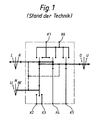
- a generic control unit is known (FIG. 1), which is used to select one of two remotely adjustable rear view mirrors and to manually control the two reversible electrical adjustment devices provided in each mirror by means of a lever strap in the manner of a short control stick.
- the mirror is selected by turning the lever handle from a stable neutral position to a right or left switching position, depending on the position of the exterior rearview mirror to be selected.
- the adjustment devices are manually controlled in a known manner by tilting the lever handle from a stable central position against a centering restoring force forwards or backwards (mirror is pivoted about its transverse axis) or to the right or left (mirror is pivoted about its vertical axis).
- Control switch units of this type are already known for the adjustment of a single - passenger-side - exterior rearview mirror.
- EP-A 0 186 192 also discloses a mirror adjustment switch with the option of selecting two different rearview mirrors, in which, however, the selection of the mirror and the manual control of the adjustment devices are carried out by means of two mechanically independent manipulations.
- Such mirror adjustment switches are generally installed in the center consoles of cars and may only take up little space there.
- the invention has for its object to design a generic control unit so that with the most compact shape and the smallest possible number of electrical connections of an arrangement to be accommodated in a confined space, the manual control of the two adjusting devices of three rearview mirrors is made possible. This object is achieved with the characterizing features of the main claim.
- control unit By dividing the control unit into a switch arrangement for the center console and a decoding and control circuit, which is installed spatially separated from the switch arrangement and is electrically connected to the switch unit by a multi-core control line - the control line transmitting at least one four-digit binary code, which both the individual Mirror as well as the respective adjustment device and its desired adjustment direction addressed, Compared to the known control unit, the structural size can be kept unchanged and the number of connecting terminals on the switch arrangement required for the adjusting device manual control can even be limited to five.
- the drawing shows both the generic control unit and an exemplary embodiment of a control unit according to the invention. Structure and function are illustrated in the following description.
- the switching bridge of the first change button shown on the left in FIG. 1 is permanently electrically connected to the switching bridge of the selector switch.
- the switching bridge of the second changeover button is permanently connected to terminal K 4 and the switch bridge of the third changeover button is connected to terminal K 5.
- Color markings are provided on the cylindrically shaped lever handle and on the base of the known control unit / switch arrangement for optical identification of the position of the lever handle - RE, N, LI - or the selector switch.
- FIGS. 1 and 2 are shown schematically, each with two adjusting devices 15.1, 15.2; 16.1, 16.2; 17.1, 17.2 and two position feedback potentiometers 18 and are connected to the decoding and control unit 13 via control lines.
- the dashed connecting lines in FIGS. 1 and 2 between the three handles shown for the sake of clarity symbolically indicate their actual union in a single lever handle 19 - 2 - axis joystick or "joystick", which is shown in FIG. 3.
- the two movable contact pieces 5.3 and 5.4 are actuated by rotating the lever handle about its longitudinal axis.
- the twelve permutations, in addition to the zero position, are sufficient to unambiguously specify the decoding and control unit 13 of the desired adjustment direction of one of the six adjustment devices.
- the lever handle 19 can be rotated on a base 20 about an axis m in three stable switching positions RA, IN, LA and can be tilted in two mutually perpendicular planes from the axis m into tilt positions o-u and l-r. It has a drop-like pointer shape known per se, by means of which its respective switching position can be sensed. Furthermore, an elongated window field 21 is provided in the upper surface of the lever handle 19, which by the light source 12 (Fig. 2) e.g. is illuminated after the vehicle parking lights are switched on and visually identifies the switch position of the lever handle even in the dark.
- a supply and control line which contains the four-wire line 14 (FIG. 2) to the decoding and control circuit 13 (FIG. 2), is connected to a multiple plug connection 22, which contains all the connection terminals 6 to 11.
- All switching bridges of the switch arrangements according to Figures 1 and 2 are designed as dumbbell-shaped switching bones. They are held in guide elements coupled with the lever handle and pressed by springs onto a printed circuit board with applied contact tracks corresponding to the connections and fixed contacts shown.
- the contact tracks for the pushbutton switches and the contact tracks for the selector switch run on the two opposite sides of the circuit board.
- a switching bone is only uncoupled from a movement of the lever handle by electrical means, although it is carried mechanically, but remains in the direction of movement with both points of contact on the same contact path without - as usual - establishing a connection between two different contact paths.
Landscapes
- Engineering & Computer Science (AREA)
- Multimedia (AREA)
- Mechanical Engineering (AREA)
- Physics & Mathematics (AREA)
- General Physics & Mathematics (AREA)
- Automation & Control Theory (AREA)
- Switches With Compound Operations (AREA)
- Rear-View Mirror Devices That Are Mounted On The Exterior Of The Vehicle (AREA)
- Motor And Converter Starters (AREA)
Description
- Die Erfindung bezieht sich auf eine Steuereinheit mit den Merkmalen des Oberbegriffs des Patentanspruchs 1.
- Eine gattungsgemäße Steuereinheit ist bekannt (Figur 1), welche der Auswahl jeweils eines von zwei fernbedient verstellbaren Rückblickspiegeln und der Handsteuerung der zwei in jedem Spiegel vorgesehenen reversierbaren elektrischen Verstelleinrichtungen mittels einer Hebelbandhabe in der Art eines kurzen Steuerknüppels dient. Die Spiegelauswahl erfolgt durch Drehen der Hebelhandhabe aus einer stabilen Neutralstellung in eine rechte oder eine linke Schaltstellung, entsprechend der Lage des auszuwählenden Außen-Rückblickspiegels.
- Die Handsteuerung der Verstelleinrichtungen erfolgt in bekannter Weise durch Kippen der Hebelhandhabe aus einer stabilen Mittellage gegen eine zentrierende Rückstellkraft nach vorn oder hinten (Spiegel wird um seine Querachse verschwenkt) bzw. nach rechts oder links (Spiegel wird um seine Hochachse verschwenkt).
- Für die Verstellung eines einzelnen - beifahrerseitigen -Außen-Rückblickspiegels sind derartige Steuerschaltereinheiten bereits bekannt.
- Schließlich ist aus der EP-A 0 186 192 ebenfalls ein Spiegelverstellschalter mit Wahlmöglichkeit für zwei verschiedene Rückblickspiegel bekannt, bei welchem jedoch die Auswahl des Spiegels und die Handsteuerung der Verstelleinrichtungen mittels zweier mechanisch voneinander unabhängiger handhaben erfolgt.
- Derartige Spiegelverstellschalter werden im allgemeinen in die Mittelkonsolen von PKW eingebaut und dürfen dort nur wenig Platz beanspruchen.
- An sich ist es bereits bekannt, mit einer Memory-Schaltung sowohl Sitz- als auch Rückblickspiegelstellungen auf Knopfdruck abrufbar zu speichern. Dies erfordert - z.B. in Kombilimousinen - auch eine Fremdkraftverstellung von bis zu drei Rückblickspiegeln - zwei außen, einer innen angeordnet.
- Der Erfindung liegt die Aufgabe zugrunde, eine gattungsgemäße Steuereinheit so auszubilden, daß bei möglichst kompakter Form und möglichst geringer Anzahl von elektrischen Anschlüssen einer in beengtem Raum unterzubringenden Anordnung die Handsteuerung der jeweils zwei Verstelleinrichtungen dreier Rückblickspiegel ermöglicht wird. Diese Aufgabe wird erfindungsgemäß mit den kennzeichnenden Merkmalen des Hauptanspruchs gelöst.
- Durch Aufteilung der Steuereinheit in eine Schalteranordnung für die Mittelkonsole und eine Decodier- und Steuerschaltung, die von der Schalteranordnung räumlich getrennt eingebaut wird und durch eine vieladrige Steuerleitung mit der Schaltereinheit elektrisch verbunden ist -wobei die Steuerleitung wenigstens einen vierstelligen Binärcode überträgt, welcher sowohl die einzelnen Spiegel als auch die jeweilige Verstelleinrichtung und deren gewünschte Verstellrichtung adressiert - ,
kann gegenüber der bekannten Steuereinheit die bauliche Größe unverändert beibehalten werden und die Anzahl der für die Verstelleinrichtungs-Handsteuerung benötigten Anschlußklemmen an der Schalteranordnung sogar auf fünf begrenzt werden. - Die kennzeichnenden Merkmale der Unteransprüche offenbaren vorteilhafte Weiterbildungen der erfindungsgemäßen Steuereinheit.
- In der Zeichnung ist sowohl die gattungsgemäße Steuereinheit als auch ein ausführungsbeispiel einer erfindungsgemäßen Steuereinheeit dargestellt. Aufbau und Funktion werden in der folgenden Beschreibung verdeutlicht.
- Es zeigen:
- Figur 1
- ein Schaltschema der bekannten Steuereinheit (Stand der Technik) ,
- Figur 2
- ein Schaltschema der erfindungsgemäßen Steuereinheit und
- Figur 3
- eine Teilansicht einer Schalteranordnung.
- An der bekannten Steuereinheit gemäß Figur 1 sind sechs Anschlußklemmen K 1, K 2, K 3, K 4, K 5 und K 6 vorgesehen. Sie enthält ferner einen Wählschalter, der in drei stabile Schaltstellungen RE, N, LI geschaltet werden kann und dessen Schaltbrücke in der Schaltstellung
- RE mit Klemme K 2,
- LI mit Klemme K 3,
- N mit keiner von beiden Klemmen verbunden ist.
- Ferner sind drei Wechseltaster mit je einer beweglichen Schaltbrücke, zwei Festkontakten und einer neutralen Mittellage vorgesehen.
- Die Schaltbrücke des ersten, in Fig. 1 links dargestellten Wechseltasters ist mit der Schaltbrücke des Wählschalters elektrisch dauernd verbunden.
- Je ein Festkontakt sowohl des ersten Wechseltasters als auch des - in der Mitte dargestellten - zweiten Wechseltasters ist an Klemme K 1 angeschlossen, während jeweils der zweite Festkontakt des ersten und des zweiten Wechseltasters sowie beide Festkontakte des dritten -rechts dargestellten - Wechseltasters gemeinsam mit der Anschlußklemme K 6 verbunden sind.
- Die Schaltbrücke des zweiten Wechseltasters ist mit der Anschlußklemme K 4 und die Schaltbrücke des dritten Wechseltasters ist mit der Anschlußklemme K 5 dauernd verbunden.
- An der zylindrisch geformten Hebelhandhabe und am Sockel der bekannten Steuereinheit/Schalteranordnung sind zur optischen Kennzeichnung der Stellung der Hebelhandhabe - RE, N, LI - bzw. des Wählschalters Farbmarkierungen vorgesehen.
- Wie aus dem Schaltschema der Figur 2 ersichtlich ist, besteht die erfindungsgemäße Steuereinheit zum einen aus einer Schalteranordnung 1
- mit einem ersten Tastschalter 2, der als Wechseltaster mit einem ersten Festkontakt 2.1
und einem zweiten Festkontakt 2.2 ausgebildet ist, - mit einem zweiten Tastschalter 3, der ebenfalls als Wechseltaster mit einem ersten Festkontakt 3.1 und einem zweiten Festkontakt 3.2 ausgebildet ist, wobei sowohl der erste Tastschalter 2 als auch der zweite Tastschalter 3 eine neutrale Mittelstellung (dargestellt) ihrer Schaltbrücke haben,
- mit einem dritten Tastschalter 4 mit einem Festkontakt 4.1,
- mit einem Wählschalter 5, der drei stabile Schaltstellungen RA, IN, LA einnehmen kann,
einen ersten Festkontakt 5.1 und
einen zweiten Festkontakt 5.2 aufweist
und dessen Schaltbrücke aus zwei mechanisch gekoppelten beweglichen Kontaktstücken 5.3 und 5.4 gebildet ist, die beide mit der Schaltbrücke des ersten Wechseltasters 2 dauernd elektrisch verbunden sind, - mit einer gemeinsamen Anschlußklemme 6,
mit der alle Festkontakte 2.1, 2.2, 3.1, 3.2 und 4.1 der drei Tastschalter 2, 3 und 4 elektrisch verbunden sind, - mit vier weiteren Anschlußklemmen 7, 8, 9 und 10, wobei
- Klemme 7
- mit dem ersten Festkontakt 5.1 des Wählschalters 5,
- Klemme 8
- mit dem zweiten Festkontakt 5.2 des Wählschalters 5,
- Klemme 9
- mit der Schaltbrücke des dritten Tastschalters 4 und
- Klemme 10
- mit der Schaltbrücke des zweiten Tastschalters/Wechseltasters 3
elektrisch verbunden ist,
- und mit einer sechsten Anschlußklemme 11, die als Versorgungsanschluß einer zwischen die gemeinsame Anschlußklemme 6 und die sechste Anschlußklemme 11 geschaltetenLichtquelle 12 an einen Lichtschalter 12.1 angeschlossen ist,
- Ferner sind schematisch drei Rückblickspiegel 15, 16 und 17 dargestellt, die jeder mit zwei Verstelleinrichtungen 15.1, 15.2; 16.1, 16.2; 17.1, 17.2 sowie zwei Positionsrückführpotentiometern 18 ausgestattet und über Steuerleitungen an die Decodier- und Steuereinheit 13 angeschlossen sind. Die gestrichelten Verbindungslinien in den Figuren 1 und 2 zwischen den der Übersichtlichkeit halber je drei dargestellten Handhaben deuten symbolisch deren tatsächliche Vereinigung in einer einzigen Hebelhandhabe 19 - 2 - Achsen - Steuerknüppel oder "Joystick" -an, die in Figur 3 dargestellt ist.
- Durch Drehung der Hebelhandhabe um ihre Längsachse werden die beiden beweglichen Kontaktstücke 5.3 und 5.4 betätigt.
- In Stellung RA ("Rechter Außenspiegel", durchgezogen dargestellt) des Tastschalters 5 liegt lediglich das Kontaktstück 5.3 am Festkontakt 5.2.
- In Stellung IN ("Innenspiegel", gestrichelt) liegt das Kontaktstück 5.3 am Festkontakt 5.1 und das Kontaktstück 5.4 am Festkontakt 5.2.
- In Stellung LA ("Linker Außenspiegel", gestrichelt) liegt lediglich das Kontaktstück 5.4 am Festkontakt 5.1.
- Durch Kippen der Hebelhandhabe, deren Längsachse in Einbaulage im Fahrzeug wenigstens annähernd senkrecht steht, aus der Mittellage m (durchgezogen)
- in Stellung o wird der erste Tastschalter 2 an den Festkontakt 2.1 angelegt, während der gleichzeitig mitbewegte dritte Tastschalter 4 potentialfrei bleibt;
- in Stellung u liegt der erste Tastschalter 2 am Festkontakt 2.2 und der dritte Tastschalter 4 am Festkontakt 4.1 an;
- in Stellung 1 liegt der erste Tastschalter 2 am Festkontakt 2.1 und der zweite Tastschalter 3 am Festkontakt 3.1 an,
während der mitbewegte dritte Tastschalter 4 wieder potentialfrei bleibt; - in Stellung r liegt der erste Tastschalter 2 am Festkontakt 2.2, der zweite Tastschalter 3 am Festkontakt 3.2 und der dritte Tastschalter 4 am Festkontakt 4.1 an.
- Unter der Annahme, daß an der gemeinsamen Anschlußklemme 6 Minus-Potential anliegt, ergeben sich tabellarisch aufgelistet folgende möglichen Kombinationen für den an den weiteren vier Anschlußklemmen 7 - 10 anstehenden Binärcode mit den Zeichen "-" für Minus-Potential und "0" für "kein Potential":

- Die zwölf Permutationen außer der Nullstellung genügen, um der Decodier- und Steuereinheit 13 die jeweils gewünschte Verstellrichtung einer der sechs Verstelleinrichtungen eindeutig vorzugeben.
- In Figur 3 ist die Schalteranordnung 1 in perspektivischer Ansicht dargestellt.
- Die hebelhandhabe 19 ist an einem Sockel 20 um eine Achse m in drei stabile Schaltstellungen RA, IN, LA drehbar und in zwei senkrecht aufeinander stehenden Ebenen aus der Achse m in Kippstellungen o - u und l - r kippbar gelagert. Sie hat eine an sich bekannte tropfenartige Zeigerform, durch welche ihre jeweilige Schaltstellung erfühlt werden kann. Ferner ist in der oberen Fläche der Hebelhandhabe 19 ein längliches Fensterfeld 21 vorgesehen, das durch die Lichtquelle 12 (Fig.2) z.B. nach Einschalten des Fahrzeugstandlichts beleuchtet wird und die Schaltstellung der Hebelhandhabe auch bei Dunkelheit optisch kennzeichnet. An einem Mehrfachsteckeranschluß 22, der sämtliche Anschlußklemmen 6 bis 11 enthält, wird eine Versorgungs- und Steuerleitung angeschlossen, die die vieradrige Leitung 14 (Fig.2) zur Decodier- und Steuerschaltung 13 (Fig.2) enthält.
- Alle Schaltbrücken der Schalteranordnungen nach Figur 1 und 2 sind als hantelförmige Schaltknochen ausgeführt. Sie werden in mit der Hebelhandhabe gekoppelten Führungselementen gehalten und von Federn auf eine Leiterplatine mit aufgetragenen, den gezeichneten Verbindungen und Festkontakten entsprechenden Kontaktbahnen gedrückt.
- Die Kontaktbahnen für die Tastschalter und die Kontaktbahnen für den Wählschalter verlaufen auf den beiden entgegengesetzten Seiten der Leiterplatine.
- Eine Abkoppelung eines Schaltknochens von einer Bewegung der Hebelhandhabe erfolgt nur auf elektrischem Weg, indem er zwar mechanisch mitgeführt wird, jedoch in der Bewegungsrichtung mit beiden Berührpunkten auf derselben Kontaktbahn verbleibt, ohne - wie üblich - eine Verbindung zwischen zwei verschiedenen Kontaktbahnen herzustellen.
Claims (5)
- Steuereinheit zur Handsteuerung von mindestens vier reversierbaren elektromechanischen Verstelleinrichtungen, insbesondere für Kraftfahrzeug-Rückblickspiegel,
mit einer Schalteranordnung (1) aus einem mittels einer Handhabe schaltbaren Wählschalter (5),
dessen Schaltbrücke in einer von drei stabilen Schaltstellungen an einem ersten Festkontakt (5.1) und in einer weiteren Schaltstellung an einem zweiten Festkontakt (5.2) des Wählschalters (5) anliegt, und
aus drei mittels derselben Handhabe schaltbaren Tastschaltern (2, 3, 4),
von denen wenigstens ein erster (2) und ein zweiter (3) als Wechseltaster mit je einer je nach Bewegungsrichtung auf einen ersten (2.1; 3.1) oder auf einen zweiten (2.2; 3.2) Festkontakt schaltbaren Schaltbrücke ausgebildet ist,
wobei die Schaltbrücke des ersten Wechseltasters (2) mit der Schaltbrücke des Wählschalters (5) elektrisch dauernd verbunden ist und bei einer Handsteuerung einer Verstelleinrichtung gemeinsam mit mindestens einer anderen Schaltbrücke eines Tastschalters (2; 3; 4) bewegt wird,
mit einer gemeinsamen Anschlußklemme (6), die mit mindestens einem Festkontakt jedes der drei Tastschalter elektrisch dauernd verbunden ist und mit vier weiteren Anschlußklemmen (7, 8, 9, 10),
die jeweils einzeln- mit dem ersten Wählschalter-Festkontakt (5.1)- mit dem zweiten Wählschalter-Festkontakt (5.2)- mit der Schaltbrücke des zweiten (3) und- mit der Schaltbrücke des dritten (4) Tastschaltersdauernd verbunden sind,
dadurch gekennzeichnet,
daß die Schaltbrücke des Wählschalters (5) der Schalteranordnung (1) in dessen dritter, vorzugsweise mittlerer Schaltstellung (IN) sowohl am ersten Festkontakt (5.1) als auch gleichzeitig am zweiten Festkontakt (5.2) des Wählschalters (5) anliegt,
daß sowohl die ersten Festkontakte (2.1; 3.1) und die zweiten Festkontakte (2.2; 3.2) des ersten (2) und des zweiten Tastschalters (3) als auch der einzige Festkontakt (4.1) des dritten Tastschalters (4) - welcher nur in einer von zwei Bewegungsrichtungen geschlossen wird - der Schalteranordnung (1)
sämtlich mit der gemeinsamen Anschlußklemme (6) dauernd elektrisch verbunden sind,
und daß wenigstens die vier weiteren Anschlußklemmen (7, 8, 9, 10) mit einer räumlich entfernt angeordneten Decodier- und Steuerschaltung (13) über eine vieladrige Leitung (14)
zur Übertragung eines vierstelligen Binärcodes mit den Zeichen "kein Potential" und "Potential der gemeinsamen Anschlußklemme (6)" verbunden sind,
wobei in zwei Stellen des Binärcodes- von den mit den beiden Festkontakten (5.1, 5.2) des Wählschalters (5) verbundenen Anschlußklemmen (7, 8) her -die Adresse eines von drei Rückblickspiegeln (15, 16 oder 17) mit je zwei Verstelleinrichtungen
und in den beiden anderen Stellen- von den mit den Schaltbrücken des zweiten (3) bzw. des dritten Tastschalters (4) verbundenen Anschlußklemmen (9, 10) her -die jeweils angesprochene Verstelleinrichtung (15.1, 15.2; 16.1, 16.2; 17.1, 17.2) und deren gewünschte Verstellrichtung codiert ist
und wobei die Decodier- und Steuerschaltung (13) gemäß dem bei Betätigung der Hebelhandhabe (19, Fig. 3) anliegenden Binärcode über
Steuerleitungen die Verstelleinrichtungen betreibt. - Steuereinheit nach Anspruch 1 ,
dadurch gekennzeichnet,
daß die Decodier- und Steuerschaltung (13) Teil einer Spiegelstellungs-Speicherschaltung (Memory) ist. - Steuereinheit nach Anspruch 1 oder 2 mit optischer Kennzeichnung der anliegenden stabilen Schaltstellung der Hebelhandhabe und einer sechsten Anschlußklemme ,
dadurch gekennzeichnet,
daß die sechste Anschlußklemme (11) der Schalteranordnung (1) mit einem dem Potential der gemeinsamen Anschlußklemme (6) wenigstens nach Betätigung eines Lichtschalters (12.1) entgegengesetzten elektrischen Potential gespeist wird
und daß zwischen die gemeinsame (6) und die sechste Anschlußklemme (11) eine Lichtquelle (12) geschaltet ist, welche durch ein Fensterfeld (21) in der Hebelhandhabe (19) scheinend deren Schaltstellung kenntlich macht. - Steuereinheit nach einem der vorstehenden Ansprüche mit Kennzeichnung der Schaltstellung der Hebelhandhabe,
dadurch gekennzeichnet,
daß die Hebelhandhabe (19) in einer Zeigerform ausgebildet ist, welche ein Ertasten ihrer Schaltstellung bzw. der Schaltstellung des Wählschalters (5) ermöglicht. - Steuereinheit nach einem der vorstehenden Ansprüche,
dadurch gekennzeichnet,
daß die Schaltbrücke des Wählschalters (5) aus zwei mechanisch gekoppelten beweglichen Kontaktstücken (5.3, 5.4) stets gleicher elektrischer Polarität besteht.
Applications Claiming Priority (2)
| Application Number | Priority Date | Filing Date | Title |
|---|---|---|---|
| DE19873721267 DE3721267A1 (de) | 1987-06-27 | 1987-06-27 | Steuereinheit zur handsteuerung von reversierbaren elektrischen verstelleinrichtungen |
| DE3721267 | 1987-06-27 |
Publications (3)
| Publication Number | Publication Date |
|---|---|
| EP0297223A2 EP0297223A2 (de) | 1989-01-04 |
| EP0297223A3 EP0297223A3 (en) | 1989-03-15 |
| EP0297223B1 true EP0297223B1 (de) | 1992-06-10 |
Family
ID=6330417
Family Applications (1)
| Application Number | Title | Priority Date | Filing Date |
|---|---|---|---|
| EP88105505A Expired - Lifetime EP0297223B1 (de) | 1987-06-27 | 1988-04-07 | Steuereinheit zur Handsteuerung von reversierbaren elektrischen Verstelleinrichtungen |
Country Status (5)
| Country | Link |
|---|---|
| US (1) | US4894650A (de) |
| EP (1) | EP0297223B1 (de) |
| JP (1) | JPH0694262B2 (de) |
| DE (1) | DE3721267A1 (de) |
| ES (1) | ES2033976T3 (de) |
Families Citing this family (13)
| Publication number | Priority date | Publication date | Assignee | Title |
|---|---|---|---|---|
| DE4008641A1 (de) * | 1990-03-17 | 1991-09-19 | Daimler Benz Ag | Steuervorrichtung zur handverstellung von reversierbaren elektrischen verstelleinrichtungen |
| US5714852A (en) * | 1996-09-13 | 1998-02-03 | United Technologies Automotive, Inc. | Three state switch detection using current sensing |
| DE19732287A1 (de) * | 1997-07-26 | 1999-01-28 | Bayerische Motoren Werke Ag | Multifunktions-Bedieneinrichtung |
| IT1305185B1 (it) * | 1998-11-17 | 2001-04-10 | Bitron Spa | Comando per gli alzacristalli elettrici di un autoveicolo. |
| US6094027A (en) * | 1999-01-11 | 2000-07-25 | Donnelly Corporation | Vehicle memory mirror position transducer |
| DE10042249A1 (de) * | 2000-08-29 | 2002-03-28 | Bosch Gmbh Robert | Digitaler Drehschalter |
| KR20020029060A (ko) * | 2002-04-04 | 2002-04-17 | 김기술 | 선재 자동용접장치 |
| IL162307A (en) * | 2004-06-02 | 2009-08-03 | Gil Hecht | Multi-purpose key assembly for an electronic device |
| IL170586A (en) * | 2005-08-30 | 2011-04-28 | Gil Hecht | Multifunction key assmbly for an electronic device |
| DE102007004673A1 (de) * | 2007-01-25 | 2008-08-07 | Teetronic Gmbh | Mehrfachschalter mit einem dreh- und kippbaren Betätiger für ein verstellbares Kontaktierteil |
| US8217832B2 (en) * | 2009-09-23 | 2012-07-10 | Andrew, Llc | Enhancing location accuracy using multiple satellite measurements based on environment |
| DE102012018742B3 (de) * | 2012-09-21 | 2014-03-13 | Audi Ag | Verfahren und Vorrichtung zur Verstellung eines Spiegels für ein Kraftfahrzeug |
| CN104723967B (zh) * | 2015-03-06 | 2017-05-03 | 钱峰 | 后视镜的调节方法 |
Family Cites Families (9)
| Publication number | Priority date | Publication date | Assignee | Title |
|---|---|---|---|---|
| FR1372453A (fr) * | 1963-04-17 | 1964-09-18 | Commutateur de circuit | |
| DE2506073C2 (de) * | 1975-02-13 | 1982-12-09 | Robert Bosch Gmbh, 7000 Stuttgart | Fernwirksystem zum selektiven Ansteuern von Verbrauchern, insbesondere in Kraftfahrzeugen |
| US4273971A (en) * | 1978-03-28 | 1981-06-16 | Lucas Industries Limited | Electrical switch having rotatable and pivotable lever |
| FR2507982A1 (fr) * | 1981-06-22 | 1982-12-24 | Britax Geco Sa | Commutateur pour la commande selective de deux retroviseurs electriques lateraux droit et gauche |
| US4428649A (en) * | 1981-06-26 | 1984-01-31 | Cherry Electrical Products Corporation | Power mirror control switch |
| EP0186192B1 (de) * | 1984-12-25 | 1993-05-19 | Ichikoh Industries Limited | Steuerschalter für die Motorfernsteuerung eines Rückspiegels in einem Fahrzeug |
| JPS61157041U (de) * | 1985-03-23 | 1986-09-29 | ||
| DE3524439A1 (de) * | 1985-07-09 | 1987-01-22 | Kirsten Elektrotech | Schalter fuer das einstellen von mindestens zwei spiegeln eines kraftfahrzeuges |
| GB8629826D0 (en) * | 1986-12-13 | 1987-01-21 | Britax Wingard Ltd | Rearview mirror |
-
1987
- 1987-06-27 DE DE19873721267 patent/DE3721267A1/de active Granted
-
1988
- 1988-04-07 ES ES198888105505T patent/ES2033976T3/es not_active Expired - Lifetime
- 1988-04-07 EP EP88105505A patent/EP0297223B1/de not_active Expired - Lifetime
- 1988-06-02 US US07/203,319 patent/US4894650A/en not_active Expired - Fee Related
- 1988-06-10 JP JP63141878A patent/JPH0694262B2/ja not_active Expired - Lifetime
Also Published As
| Publication number | Publication date |
|---|---|
| DE3721267C2 (de) | 1990-03-22 |
| JPS644553A (en) | 1989-01-09 |
| US4894650A (en) | 1990-01-16 |
| DE3721267A1 (de) | 1989-01-05 |
| ES2033976T3 (es) | 1993-04-01 |
| EP0297223A2 (de) | 1989-01-04 |
| EP0297223A3 (en) | 1989-03-15 |
| JPH0694262B2 (ja) | 1994-11-24 |
Similar Documents
| Publication | Publication Date | Title |
|---|---|---|
| EP0447770B1 (de) | Steuervorrichtung zur Handverstellung von reversierbaren elektrischen Verstelleinrichtungen | |
| DE3721267C2 (de) | ||
| DE69719254T2 (de) | Multifunktions-Schalteinrichtung und Fahrzeugbetriebssystem mit einer derartigen Schalteinrichtung | |
| DE2628744C2 (de) | Träger für Schalter und Anzeigen für Fahrzeuge | |
| DE19713978C2 (de) | Kippschaltvorrichtung | |
| DE3040546C2 (de) | Codierschalter | |
| DE19712048C2 (de) | Bedienvorrichtung | |
| DE3717251C2 (de) | Elektrischer Schalter, insbesondere Lenkstockschalter für Kraftfahrzeuge | |
| EP0608771A1 (de) | Verfahren und Vorrichtung zum Betätigen von Einbaukomponenten in Kraftfahrzeugen | |
| DE69704556T2 (de) | Lenksäuleschaltervorrichtung für ein kraftfahrzeug | |
| DE10060981B4 (de) | Betätigungseinrichtung zum Auslösen wenigstens einer Funktion eines Kraftfahrzeugs | |
| DE3854201T2 (de) | Schaltanordnung. | |
| DE3149377C2 (de) | Schaltvorrichtung für Signalgeber von Kraftfahrzeugen | |
| DE3437456C1 (de) | Steuervorrichtung fuer Computer | |
| DE69517897T2 (de) | Manuelles Mehrfunktionssteuergerät | |
| EP0275392A1 (de) | Chirurgische Knochenbohrmaschine | |
| EP1021313A1 (de) | Elektrischer hebelschalter | |
| DE10046749C1 (de) | Wipptastenanordnung | |
| EP0554687B1 (de) | Wipptastenanordnung mit einer Vierfachwippe für die Betätigung elektrischer Tippschalter | |
| DE19714955A1 (de) | Schalteranordnung | |
| DE102005046801A1 (de) | Elektrische Schalteinrichtung | |
| DE19750610C2 (de) | Elektrisches Universalschaltwerk | |
| DE9201312U1 (de) | Konsole für elektrische Schaltgeräte | |
| DE69117687T2 (de) | Schalteranordnung für ein Kraftfahrzeug | |
| DE1072895B (de) | Handbetätigbarer Schalter für elektrische Anlagen auf Fahrzeugen, insbesondere Kraftfahrzeugen |
Legal Events
| Date | Code | Title | Description |
|---|---|---|---|
| PUAI | Public reference made under article 153(3) epc to a published international application that has entered the european phase |
Free format text: ORIGINAL CODE: 0009012 |
|
| AK | Designated contracting states |
Kind code of ref document: A2 Designated state(s): ES FR GB IT SE |
|
| PUAL | Search report despatched |
Free format text: ORIGINAL CODE: 0009013 |
|
| AK | Designated contracting states |
Kind code of ref document: A3 Designated state(s): ES FR GB IT SE |
|
| 17P | Request for examination filed |
Effective date: 19890401 |
|
| 17Q | First examination report despatched |
Effective date: 19911106 |
|
| GRAA | (expected) grant |
Free format text: ORIGINAL CODE: 0009210 |
|
| AK | Designated contracting states |
Kind code of ref document: B1 Designated state(s): ES FR GB IT SE |
|
| ITF | It: translation for a ep patent filed | ||
| GBT | Gb: translation of ep patent filed (gb section 77(6)(a)/1977) | ||
| ET | Fr: translation filed | ||
| REG | Reference to a national code |
Ref country code: ES Ref legal event code: FG2A Ref document number: 2033976 Country of ref document: ES Kind code of ref document: T3 |
|
| PLBE | No opposition filed within time limit |
Free format text: ORIGINAL CODE: 0009261 |
|
| STAA | Information on the status of an ep patent application or granted ep patent |
Free format text: STATUS: NO OPPOSITION FILED WITHIN TIME LIMIT |
|
| ITTA | It: last paid annual fee | ||
| 26N | No opposition filed | ||
| EAL | Se: european patent in force in sweden |
Ref document number: 88105505.7 |
|
| PGFP | Annual fee paid to national office [announced via postgrant information from national office to epo] |
Ref country code: GB Payment date: 19990326 Year of fee payment: 12 |
|
| PGFP | Annual fee paid to national office [announced via postgrant information from national office to epo] |
Ref country code: ES Payment date: 19990422 Year of fee payment: 12 |
|
| PGFP | Annual fee paid to national office [announced via postgrant information from national office to epo] |
Ref country code: SE Payment date: 19990423 Year of fee payment: 12 |
|
| PGFP | Annual fee paid to national office [announced via postgrant information from national office to epo] |
Ref country code: FR Payment date: 19990427 Year of fee payment: 12 |
|
| REG | Reference to a national code |
Ref country code: GB Ref legal event code: 732E |
|
| PG25 | Lapsed in a contracting state [announced via postgrant information from national office to epo] |
Ref country code: GB Free format text: LAPSE BECAUSE OF NON-PAYMENT OF DUE FEES Effective date: 20000407 |
|
| PG25 | Lapsed in a contracting state [announced via postgrant information from national office to epo] |
Ref country code: SE Free format text: LAPSE BECAUSE OF NON-PAYMENT OF DUE FEES Effective date: 20000408 Ref country code: ES Free format text: THE PATENT HAS BEEN ANNULLED BY A DECISION OF A NATIONAL AUTHORITY Effective date: 20000408 |
|
| GBPC | Gb: european patent ceased through non-payment of renewal fee |
Effective date: 20000407 |
|
| EUG | Se: european patent has lapsed |
Ref document number: 88105505.7 |
|
| PG25 | Lapsed in a contracting state [announced via postgrant information from national office to epo] |
Ref country code: FR Free format text: LAPSE BECAUSE OF NON-PAYMENT OF DUE FEES Effective date: 20001229 |
|
| REG | Reference to a national code |
Ref country code: FR Ref legal event code: ST |
|
| REG | Reference to a national code |
Ref country code: ES Ref legal event code: FD2A Effective date: 20020204 |
|
| PG25 | Lapsed in a contracting state [announced via postgrant information from national office to epo] |
Ref country code: IT Free format text: LAPSE BECAUSE OF NON-PAYMENT OF DUE FEES Effective date: 20050407 |