EP0295731B1 - Twisting device for giving a false twisting to a textile fibre sliver - Google Patents
Twisting device for giving a false twisting to a textile fibre sliver Download PDFInfo
- Publication number
- EP0295731B1 EP0295731B1 EP88200983A EP88200983A EP0295731B1 EP 0295731 B1 EP0295731 B1 EP 0295731B1 EP 88200983 A EP88200983 A EP 88200983A EP 88200983 A EP88200983 A EP 88200983A EP 0295731 B1 EP0295731 B1 EP 0295731B1
- Authority
- EP
- European Patent Office
- Prior art keywords
- sliver
- spiral element
- bobbin
- winding
- false twisting
- Prior art date
- Legal status (The legal status is an assumption and is not a legal conclusion. Google has not performed a legal analysis and makes no representation as to the accuracy of the status listed.)
- Expired - Lifetime
Links
- 239000004753 textile Substances 0.000 title claims description 9
- 239000000835 fiber Substances 0.000 title claims description 6
- 238000004804 winding Methods 0.000 claims description 23
- 230000015572 biosynthetic process Effects 0.000 claims description 7
- 238000011144 upstream manufacturing Methods 0.000 claims description 3
- 230000000737 periodic effect Effects 0.000 claims 1
- 238000004519 manufacturing process Methods 0.000 description 2
- 239000000463 material Substances 0.000 description 2
- 238000004873 anchoring Methods 0.000 description 1
- 230000004323 axial length Effects 0.000 description 1
- 238000010586 diagram Methods 0.000 description 1
- 238000000034 method Methods 0.000 description 1
- 238000009987 spinning Methods 0.000 description 1
Images
Classifications
-
- D—TEXTILES; PAPER
- D01—NATURAL OR MAN-MADE THREADS OR FIBRES; SPINNING
- D01H—SPINNING OR TWISTING
- D01H7/00—Spinning or twisting arrangements
- D01H7/92—Spinning or twisting arrangements for imparting transient twist, i.e. false twist
-
- B—PERFORMING OPERATIONS; TRANSPORTING
- B65—CONVEYING; PACKING; STORING; HANDLING THIN OR FILAMENTARY MATERIAL
- B65H—HANDLING THIN OR FILAMENTARY MATERIAL, e.g. SHEETS, WEBS, CABLES
- B65H59/00—Adjusting or controlling tension in filamentary material, e.g. for preventing snarling; Applications of tension indicators
- B65H59/005—Means compensating the yarn tension in relation with its moving due to traversing arrangements
-
- B—PERFORMING OPERATIONS; TRANSPORTING
- B65—CONVEYING; PACKING; STORING; HANDLING THIN OR FILAMENTARY MATERIAL
- B65H—HANDLING THIN OR FILAMENTARY MATERIAL, e.g. SHEETS, WEBS, CABLES
- B65H2701/00—Handled material; Storage means
- B65H2701/30—Handled filamentary material
- B65H2701/31—Textiles threads or artificial strands of filaments
- B65H2701/311—Slivers
Definitions
- the present invention relates to a twisting device for giving a false twist to a textile fibre sliver between the outlet calender of a drawing frame and a winding unit having a bobbin winding carriage, which is reciprocating parallel to the axis of the bobbin being formed and which supports an active false twisting unit with a revolving funnel.
- sliver will be uniformly used in order to indicate both a roving of textile fibres, or a sliver of textile fibres, or, anyway, an aggregate of textile fibres.
- the bobbin On a drawing frame on which the sliver is collected on bobbins of a traditional type, the bobbin is produced by winding the sliver around an idle roll, driven to revolve by one or more slotted rolls, by means of an active false twisting unit which gives the sliver roundness and mechanical strength and maintains the individuality thereof during the subsequent unwinding process.
- the active false twisting unit In order to allow a cross-wound sliver bobbin to be formed, the active false twisting unit is supported by a bobbin winding carriage to which a reciprocating movement along a transversal stroke is given, which is substantially equal to the length of the desired bobbin.
- the sliver must be subjected to the due winding tension prerequisite for a compact bobbin to form, but said tension should be kept sufficiently constant, in order not to reach such values as to modify the dimensional and size characteristics of the sliver between the point of outlet from the outlet calender, and the point wherein the winding operation takes place. Relatively high changes in tension could even cause the sliver to break. One can easily understand how such a breakage would interrupt the production process, obliging the attending operator to take action. The labour cost for these emergency operations represents a considerable factor when the production costs are computed.
- US-A-3,670,978 proposes, e.g., to make the sliver run inside a ring constituting an intermediate guide, installed, in a movable way, between the point of outlet from the outlet calender of the drawing frame and the bobbin winding system, in such a way that the total of the respective distances of said ring relatively to the outlet from the outlet calender and to the sliver guide remains always constant.
- several systems have already been proposed and realized which envisage, e.g. articulated toggle-levers, or the like, capable of realizing the desired kinetic system.
- EP-A-0 070 814 discloses a device, the main task of which is that of compensating the variable distance between the fixed sliver outlet point from the drawing frame and the movable point wherein the winding of the sliver on the bobbin takes place.
- this known device comprises a flexible support in the form of a spiral element with entry guide ring, positioned upstream the active false twisting unit with revolving funnel.
- Said spiral element at its end provided with the entry guide ring, is secured by means of a support to the drawing frame, whereas its outlet end is secured to the inlet of the revolving funnel.
- the sliver is guided by the spiral element along its whole length between the outlet calender of the drawing frame and the revolving funnel and is subjected to fast wear due to the frictional contact with the spiral element.
- the purpose of the present invention is to provide a twisting device, which avoids the mentioned drawbacks affecting the devices known from the prior art and which is capable of supplying the textile fibre sliver leaving the outlet calender of the drawing frame with an effective bond and compactness between the fibres, already before it enters the active false twisting unit, so as to render the sliver totally elastic and capable of supporting the necessary tension due to the differences in length during the winding operation.
- the twisting device of the present invention is simply constituted by a spiral element connected only to the bobbin winding carriage, it has a very small inertia as necessary in order not to substantially apply a burden to the active false twisting unit supported by the bobbin winding carriage during its reciprocating motion. Thus, vibrations are avoided and the sliver does not undergo wear and damages.
- the spiral element gives false twists to the sliver already before it enters the active false twisting unit, supplying it with such a bond and such a compactness between the fibres, as to render it totally elastic and capable of supporting the necessary tension to be applied for performing the cross-winding operation. More specifically, the spiral element performs the task of guiding the tape to the inlet of the revolving funnel, with simultaneously supplying the same sliver a false twist in a predetermined direction running towards the outlet calender and furthermore carries out the first step of sliver compacting and rounding before said sliver enters the active false twisting unit.
- the twist given to the sliver when this latter leaves the outlet calender by means of the spiral element keeps advantageously mutually bound the fibres which compose the same sliver, making it possible it to be put under tension, in order to elastically extend it, realizing a perfect compensation for the change in distance, with no risk of formation of false drafts. Thanks to this combination, and to this particular arrangement, the compensation and the false sliver twisting are realized by means of simple means, and, thanks to the low weight of the spiral element, the winding speed can be substantially increased on the machine.
- the whole assembly constituted by the combination of the spiral element and of the revolving funnel is light enough, so that it can be applied to the various machine types, and is also considerably cheap.
- Said combination makes it possible very fragile slivers to be processed without any difficulties, such as, e.g., slivers constituted by short, low-cohesion fibres and makes it possible breakages and interruptions in the continuity of the fibre aggregate, as well as a mutual slipping of the fibres, and therefore changes in cross-section surface area - which endanger the quality of the same sliver - to be avoided in these cases.
- the spiral element has a substantially cylindrical shape and an inner diameter of positive value.
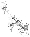
- Said figure is a diagram schematically showing a side view of the twisting device according to the present invention, in upstream cooperation with the outlet calender through which the sliver leaves the drawing frame, and in downstream cooperation with the system of cross winding for the formation of the bobbin on which the sliver is collected.
- Said ring is given an inner ring surface with a spherical outline converging in the direction of feed of the sliver 6, which results to be guided into the interior of the spiral element 10;
- 10 is a spiral element having a helical-spring shape, with an inner diameter of positive value, and with a pitch and a number of turns which depend on the spinning frame and on the material being processed.
- Said spiral element 10 has two ends, one of which is destined to be fastened to the guide ring 8, and the other one is destined to be fastened to the bracket 12; 12 is a bracket which makes it possible the spiral element 10 to be rigidly connected to the active false twisting unit; 14 is the body of the false twisting unit; 16 is the revolving funnel of the body 14, for giving the sliver 6 false twists necessary for supplying said sliver with roundness and mechanical strength before it is collected on the periphery of the bobbin 30 under way of formation; 18 is the connection and support plate for supporting the body 14, and connecting it to the reciprocating carriage 20, driven to move parallelly to the axis of the bobbin 30 under way of formation; 24 is the sleeve sliding along the cylindrical guide bar 22 positioned parallel to the axis 34 of the roll 32 which drives the bobbin under way of formation 30; 26 is the flat structural shape which supports the whole carriage 20 provided with reciprocating motion with a transversal stroke substantially equal to the axial length of the desired
- the sliver, or roving, or aggregate of fibres leaving the outlet calender 3 is entered into the guide ring 8 through the side slot and is conveyed, through the spiral, element 10, into the revolving funnel 16 in order to be collected on the periphery of the bobbin under way of formation 30 revolving on the winding spindle 28.
- the shape, the ratios and the size of the parts may be changed;
- the wire which constitutes the spiral element may be of a different suitable material;
- the anchoring elements 12 and 18 may be given a different shape, or may be mounted in a different way, without thereby departing from the scope of the solution as proposed by the present invention, as claimed in the hereto appended claim.
Landscapes
- Engineering & Computer Science (AREA)
- Textile Engineering (AREA)
- Mechanical Engineering (AREA)
- Spinning Or Twisting Of Yarns (AREA)
- Braiding, Manufacturing Of Bobbin-Net Or Lace, And Manufacturing Of Nets By Knotting (AREA)
Applications Claiming Priority (2)
| Application Number | Priority Date | Filing Date | Title |
|---|---|---|---|
| IT2095987 | 1987-06-19 | ||
| IT20959/87A IT1205058B (it) | 1987-06-19 | 1987-06-19 | Dispositivo torsionatore per carro bobinatore |
Publications (2)
| Publication Number | Publication Date |
|---|---|
| EP0295731A1 EP0295731A1 (en) | 1988-12-21 |
| EP0295731B1 true EP0295731B1 (en) | 1992-11-04 |
Family
ID=11174643
Family Applications (1)
| Application Number | Title | Priority Date | Filing Date |
|---|---|---|---|
| EP88200983A Expired - Lifetime EP0295731B1 (en) | 1987-06-19 | 1988-05-17 | Twisting device for giving a false twisting to a textile fibre sliver |
Country Status (5)
| Country | Link |
|---|---|
| EP (1) | EP0295731B1 (enExample) |
| DE (1) | DE3875656T2 (enExample) |
| ES (1) | ES2037199T3 (enExample) |
| GR (1) | GR3006374T3 (enExample) |
| IT (1) | IT1205058B (enExample) |
Families Citing this family (4)
| Publication number | Priority date | Publication date | Assignee | Title |
|---|---|---|---|---|
| IT1223533B (it) * | 1987-12-18 | 1990-09-19 | Savio Spa | Elemento a spirale rotante per impartire compensazione e falsa torsione ai nastri di fibre tessili |
| IT1223525B (it) * | 1987-12-18 | 1990-09-19 | Savio Spa | Dispositivo torsionatore con spirale rotante per carro bobinatore |
| IT1237925B (it) * | 1989-12-21 | 1993-06-18 | Savio Spa | Dispositivo torsionatore perfezionato per carro bobinatore che permette di formare bobine compatte |
| IT1237922B (it) * | 1989-12-21 | 1993-06-18 | Savio Spa | Dispositivo torsionatore perfezionato per carro bobinatore che permette di formare una bobina di perfetta forma cilindrica |
Citations (1)
| Publication number | Priority date | Publication date | Assignee | Title |
|---|---|---|---|---|
| GB2104923A (en) * | 1981-07-03 | 1983-03-16 | Sant Andrea Novara Officine | Sliver winder with traversing false twister |
Family Cites Families (5)
| Publication number | Priority date | Publication date | Assignee | Title |
|---|---|---|---|---|
| CH427589A (de) * | 1964-03-09 | 1966-12-31 | Reiter Michael | Beweglicher Band- oder Vorgarnführer zum Herstellen von Kreuzwickeln |
| BE659089A (enExample) * | 1965-01-29 | |||
| FR1502636A (fr) * | 1966-01-21 | 1967-11-24 | Schlumberger Cie N | Perfectionnements aux entonnoirs tournants utilisés pour l'enroulage des rubans de fibres en bobines croisées |
| US3670978A (en) * | 1970-10-02 | 1972-06-20 | Warner Swasey Co | Compensator device |
| AU8554382A (en) * | 1981-07-20 | 1983-01-27 | Officine Savio S.P.A. | Compensator device |
-
1987
- 1987-06-19 IT IT20959/87A patent/IT1205058B/it active
-
1988
- 1988-05-17 DE DE8888200983T patent/DE3875656T2/de not_active Expired - Fee Related
- 1988-05-17 EP EP88200983A patent/EP0295731B1/en not_active Expired - Lifetime
- 1988-05-17 ES ES198888200983T patent/ES2037199T3/es not_active Expired - Lifetime
-
1992
- 1992-11-27 GR GR920402748T patent/GR3006374T3/el unknown
Patent Citations (1)
| Publication number | Priority date | Publication date | Assignee | Title |
|---|---|---|---|---|
| GB2104923A (en) * | 1981-07-03 | 1983-03-16 | Sant Andrea Novara Officine | Sliver winder with traversing false twister |
Also Published As
| Publication number | Publication date |
|---|---|
| DE3875656D1 (de) | 1992-12-10 |
| EP0295731A1 (en) | 1988-12-21 |
| DE3875656T2 (de) | 1993-04-15 |
| IT1205058B (it) | 1989-03-10 |
| GR3006374T3 (enExample) | 1993-06-21 |
| ES2037199T3 (es) | 1993-06-16 |
| IT8720959A0 (it) | 1987-06-19 |
Similar Documents
| Publication | Publication Date | Title |
|---|---|---|
| US6318060B1 (en) | Method and spinning machine for the production of core yarn | |
| EP0375242A2 (en) | Manufacture of roving | |
| US4484435A (en) | Method and device for the production of textile fibre yarns | |
| EP0295731B1 (en) | Twisting device for giving a false twisting to a textile fibre sliver | |
| GB2151265A (en) | Drafting method and apparatus in spinning machine | |
| US4819422A (en) | Arrangement for winding a double yarn onto a cross-wound spool | |
| EP0638673A1 (en) | Fluff suppression apparatus | |
| CN1589342A (zh) | 纺纱机上用于压实纤维须条的装置 | |
| US3503197A (en) | Process and apparatus for drawing and twisting fibrous slivers | |
| EP0295733B1 (en) | Spiral element for supplying textile fibre slivers with compensation and false twist | |
| EP0070814B1 (en) | Compensator device for the bobbin-winding carriage in textile machines | |
| EP0321011B1 (en) | Twister device with rotary spiral for a winding carriage | |
| US4112667A (en) | Apparatus and process suitable for twist-drawing a yarn | |
| CN117265728A (zh) | 一种变频器加工用包芯纱装置及变频器加工工艺 | |
| CN106687628B (zh) | 生产包芯纱的设备 | |
| EP0321034B1 (en) | Rotary spiral element for introducing compensation and false twist into textile fibre slivers | |
| US2732682A (en) | kyame | |
| CN110268111B (zh) | 用于加工纤维的方法和设备 | |
| US3300956A (en) | Core-spinning apparatus | |
| CN112921454A (zh) | 一种加捻卷绕分离式环锭纺纱系统 | |
| US4768337A (en) | Process and arrangement for producing feed spools for a twisting operation | |
| US4389751A (en) | Apparatus for severing a fibre layer of staple fibres | |
| CN219620585U (zh) | 一种用于纺织丝线的卷线装置 | |
| US4370850A (en) | Roving frame and a method of packaging roving | |
| US4185451A (en) | Apparatus and process suitable for twist-drawing a yarn |
Legal Events
| Date | Code | Title | Description |
|---|---|---|---|
| PUAI | Public reference made under article 153(3) epc to a published international application that has entered the european phase |
Free format text: ORIGINAL CODE: 0009012 |
|
| AK | Designated contracting states |
Kind code of ref document: A1 Designated state(s): BE CH DE ES FR GB GR LI |
|
| 17P | Request for examination filed |
Effective date: 19890511 |
|
| 17Q | First examination report despatched |
Effective date: 19901221 |
|
| RTI1 | Title (correction) | ||
| GRAA | (expected) grant |
Free format text: ORIGINAL CODE: 0009210 |
|
| AK | Designated contracting states |
Kind code of ref document: B1 Designated state(s): BE CH DE ES FR GB GR LI |
|
| ET | Fr: translation filed | ||
| REF | Corresponds to: |
Ref document number: 3875656 Country of ref document: DE Date of ref document: 19921210 |
|
| PGFP | Annual fee paid to national office [announced via postgrant information from national office to epo] |
Ref country code: GR Payment date: 19930414 Year of fee payment: 6 |
|
| REG | Reference to a national code |
Ref country code: GR Ref legal event code: FG4A Free format text: 3006374 |
|
| PGFP | Annual fee paid to national office [announced via postgrant information from national office to epo] |
Ref country code: GB Payment date: 19930505 Year of fee payment: 6 |
|
| PGFP | Annual fee paid to national office [announced via postgrant information from national office to epo] |
Ref country code: FR Payment date: 19930518 Year of fee payment: 6 |
|
| PGFP | Annual fee paid to national office [announced via postgrant information from national office to epo] |
Ref country code: ES Payment date: 19930519 Year of fee payment: 6 Ref country code: BE Payment date: 19930519 Year of fee payment: 6 |
|
| PG25 | Lapsed in a contracting state [announced via postgrant information from national office to epo] |
Ref country code: LI Effective date: 19930531 Ref country code: CH Effective date: 19930531 |
|
| REG | Reference to a national code |
Ref country code: ES Ref legal event code: FG2A Ref document number: 2037199 Country of ref document: ES Kind code of ref document: T3 |
|
| PLBE | No opposition filed within time limit |
Free format text: ORIGINAL CODE: 0009261 |
|
| STAA | Information on the status of an ep patent application or granted ep patent |
Free format text: STATUS: NO OPPOSITION FILED WITHIN TIME LIMIT |
|
| 26N | No opposition filed | ||
| REG | Reference to a national code |
Ref country code: CH Ref legal event code: PL |
|
| PG25 | Lapsed in a contracting state [announced via postgrant information from national office to epo] |
Ref country code: DE Effective date: 19940201 |
|
| PG25 | Lapsed in a contracting state [announced via postgrant information from national office to epo] |
Ref country code: GB Effective date: 19940517 |
|
| PG25 | Lapsed in a contracting state [announced via postgrant information from national office to epo] |
Ref country code: ES Free format text: LAPSE BECAUSE OF NON-PAYMENT OF DUE FEES Effective date: 19940518 |
|
| PG25 | Lapsed in a contracting state [announced via postgrant information from national office to epo] |
Ref country code: BE Effective date: 19940531 |
|
| BERE | Be: lapsed |
Owner name: SAVIO S.P.A. Effective date: 19940531 |
|
| PG25 | Lapsed in a contracting state [announced via postgrant information from national office to epo] |
Ref country code: GR Free format text: THE PATENT HAS BEEN ANNULLED BY A DECISION OF A NATIONAL AUTHORITY Effective date: 19941130 |
|
| GBPC | Gb: european patent ceased through non-payment of renewal fee |
Effective date: 19940517 |
|
| PG25 | Lapsed in a contracting state [announced via postgrant information from national office to epo] |
Ref country code: FR Effective date: 19950131 |
|
| REG | Reference to a national code |
Ref country code: FR Ref legal event code: ST |
|
| REG | Reference to a national code |
Ref country code: GR Ref legal event code: MM2A Free format text: 3006374 |
|
| REG | Reference to a national code |
Ref country code: ES Ref legal event code: FD2A Effective date: 19990301 |