EP0294262A1 - Apparatus for extruding alveolar ceramic articles - Google Patents
Apparatus for extruding alveolar ceramic articles Download PDFInfo
- Publication number
- EP0294262A1 EP0294262A1 EP88401194A EP88401194A EP0294262A1 EP 0294262 A1 EP0294262 A1 EP 0294262A1 EP 88401194 A EP88401194 A EP 88401194A EP 88401194 A EP88401194 A EP 88401194A EP 0294262 A1 EP0294262 A1 EP 0294262A1
- Authority
- EP
- European Patent Office
- Prior art keywords
- face
- bars
- block
- bar
- slots
- Prior art date
- Legal status (The legal status is an assumption and is not a legal conclusion. Google has not performed a legal analysis and makes no representation as to the accuracy of the status listed.)
- Withdrawn
Links
Images

Classifications
-
- B—PERFORMING OPERATIONS; TRANSPORTING
- B28—WORKING CEMENT, CLAY, OR STONE
- B28B—SHAPING CLAY OR OTHER CERAMIC COMPOSITIONS; SHAPING SLAG; SHAPING MIXTURES CONTAINING CEMENTITIOUS MATERIAL, e.g. PLASTER
- B28B3/00—Producing shaped articles from the material by using presses; Presses specially adapted therefor
- B28B3/20—Producing shaped articles from the material by using presses; Presses specially adapted therefor wherein the material is extruded
- B28B3/26—Extrusion dies
- B28B3/269—For multi-channeled structures, e.g. honeycomb structures
Definitions
- the present invention relates to a device for extruding ceramic materials to form cellular structures.
- This device is more particularly intended for the formation of such structures having very thin walls, of the order of one to a few tenths of a millimeter, with a relatively large mesh (cells of at least 1 mm side).
- the object of the invention is to propose a tool for the extrusion of a ceramic honeycomb structure which does not have this drawback.
- this tool has the advantage of being modular and of being easy to clean.
- the extrusion device according to the invention intended for the formation of a cellular honeycomb structure, formed of a block in one face of which are formed entry openings for the ceramic paste, communicating through the block with a network of crossed slots open in the opposite face of this block for the formation of the honeycomb structure, is characterized in that the block is formed by assembling bars of rectangular section, joined by their vertical faces, the inlet openings being formed by notches made in at least one of said vertical faces from each upper face of the bars, while the network slots are formed, for some by a recess made in the lower part of at least one of the vertical faces of each bar, and for the others by grooves starting from the lower face of each bar from one vertical face to the other, with the exception of the end bars.
- each notch has between two sides perpendicular to the vertical faces, an oblique bottom inclined with respect to these faces, the notch having a variable depth between a maximum value on the upper face and a zero value at a point above the underside.
- the notches on each intermediate bar, are arranged facing one another, the notches of the adjacent bars corresponding to each other.
- a recess is produced at the lower part of each bar, providing a flat face recessed with respect to said vertical face and, moreover, a bleeding is carried out along the vertical plane of symmetry of each notch, in the lower face of each intermediate bar, of a height such that it overlaps the bottom of the notch.
- the bars have, at each of their ends, bores for the passage of positioning and holding pins.
- the slots made between the bars are closed at their ends by a plate or belt bearing on the end bars and which provides with the intermediate bars at the end and over a length slightly reduced compared to that of the end bars, a blade-shaped gap delimiting a peripheral outlet slot of the honeycomb structure.
- the device according to the invention consists of a set of bars, each having a generally parallelepiped shape, this set comprising bars 10, similar to each other, stacked next to each other, between two end bars 11 and 12.
- the assembly of these bars forms a plate P having in plan a rectangular or square shape, the cohesion of this assembly being ensured by means of two pins not shown passing through bores 13 formed at each of the ends of said bars for the positioning of these ci and comprising means of approximation and tightening of these bars.
- Each bar 10, and each of the end bars 11 and 12 has a rectangular cross section, and has an upper face 15, a lower face 16 and two vertical faces 17 and 18.
- each notch 20 On each vertical face 17, 18 of the central bars 10 and on the internal vertical faces of the end bars 11 and 12, a series of notches 20 are formed, produced for example by milling, each notch 20 having between two sides 21, perpendicular to the faces 17, 18, an oblique bottom 22, inclined with respect to these faces, the notch 20 having a variable depth between a maximum value on the upper face 15 and a zero value at a distance d from the lower face 16, at a point above this face.
- the notches 20, which are regularly distributed, are arranged facing one face 17, 18 to the other, the bottoms of two opposite notches 20 leaving a narrow band of material 23 between them. upper face 15.
- the notches 20 of the adjacent bars correspond.
- a recess 25 On one of the vertical faces of the bar, on the face 17 in this example, is produced at the lower part of each bar 10, a recess 25, providing a flat face 26, set back from the face 17 of a depth e , and parallel to this face. This recess is located at a distance D (see FIG. 6) from the lower face 16 of the bar, D being greater than d.
- each notch is formed in the lower face 16 of each bar, with the exception of the bars and end notches, a groove 28, of a width l equal to e and of a height substantially equal to D (fig. 4, 5 and 6), so as to overlap the bottom of this notch.
- a block is obtained in one of the faces (produced by juxtaposition of the faces 15) from which openings 30 formed each by combining two notches 20 of two bars adjacent (fig. 3), while in the other face (juxtaposition of the faces 16) opens a network of slots 31, perpendicular to each other, formed by the grooves 28 and the recesses 25, the slot in the latter case being formed by the faces 26 and the adjacent faces 18 (fig. 6).
- the end bars 11 and 12 have relative to the current bars 10 on the side of the lower face 16 and at each end an excess of length corresponding to the thickness of a slot 31 at the periphery of the honeycomb structure.
- a belt element (not shown) to the assembled bars, the end of the slots formed by the recesses 25 is closed by a peripheral slot 31a which may possibly be thicker than the network slots 31.
- the slots 31b formed in contact with the end bars 11 and 12 may have a greater thickness corresponding to the peripheral envelope of the honeycomb structure.
- the openings 30 and these slots 31 communicate with each other.
- ceramic paste pushed back through the openings 30, by any suitable means is extruded by the grid network of the slots 31, to form the desired cellular structure.
- the tooling according to the present invention is very particularly suitable for the extrusion of elements intended to be subjected to high temperatures and pressures, for example filter elements for liquid metals, in which case these elements are formed of refractory materials.
Abstract
Description
La présente invention se rapporte à un dispositif d'extrusion de matériaux céramiques pour former des structures alvéolaires.The present invention relates to a device for extruding ceramic materials to form cellular structures.
Ce dispositif est plus particulièrement destiné à la formation de telles structures présentant des parois très minces, de l'ordre de un à quelques dixièmes de millimètres, avec une maille relativement importante (alvéoles d'au moins 1 mm de côté).This device is more particularly intended for the formation of such structures having very thin walls, of the order of one to a few tenths of a millimeter, with a relatively large mesh (cells of at least 1 mm side).
Pour réaliser ce genre d'extrusion, on a habituellement recours à des outillages monolithiques, qui sont d'une fabrication très délicate puisque, généralement, on doit réaliser un premier réseau de trous percés, par exemple, dans une face d'un bloc d'acier, débouchant dans un second réseau de fentes croisées, réalisées dans la face opposée de ce bloc et constituant la filière de la structure alvéolaire, lorsque la pâte de céramique traverse l'outillage, repoussée à travers le premier réseau de trous pour s'échapper par le réseau de fentes croisées.To achieve this kind of extrusion, we usually use monolithic tools, which are very delicate to manufacture since, generally, we must make a first network of drilled holes, for example, in one face of a block of steel, opening into a second network of crossed slots, made in the opposite face of this block and constituting the die of the honeycomb structure, when the ceramic paste passes through the tooling, pushed back through the first network of holes for s' escape through the network of crossed slits.
La réalisation de cet outillage est longue et coûteuse et nécessite une grande précision. Il est même impossible à réaliser dans le cas de matrices de grande taille.The production of this tool is long and expensive and requires great precision. It is even impossible to achieve in the case of large matrices.
L'invention a pour objet de proposer un outillage pour l'extrusion de structure alvéolaire en céramique ne présentant pas cet inconvénient. De plus, cet outillage présente l'avantage d'être modulable et d'être facile à nettoyer.The object of the invention is to propose a tool for the extrusion of a ceramic honeycomb structure which does not have this drawback. In addition, this tool has the advantage of being modular and of being easy to clean.
Le dispositif d'extrusion selon l'invention, destiné à la formation de structure alvéolaire en céramique, formé d'un bloc dans une face duquel sont ménagées des ouvertures d'entrée de la pâte céramique, communiquant à travers le bloc avec un réseau de fentes croisées ouvertes dans la face opposée de ce bloc pour la formation de la structure alvéolaire, est caractérisé en ce que le bloc est formé par assemblage de barrettes de section rectangulaire, accolées par leurs faces verticales, les ouvertures d'entrée étant ménagées par des encoches pratiquées dans au moins une desdites faces verticales à partir de chaque face supérieure des barrettes, tandis que les fentes du réseau sont formées, pour les unes par un décrochement pratiqué dans la partie inférieure d'au moins une des faces verticales de chaque barrette, et pour les autres par des saignées partant de la face inférieure de chaque barrette d'une face verticale à l'autre, à l'exception des barrettes d'extrémité.The extrusion device according to the invention, intended for the formation of a cellular honeycomb structure, formed of a block in one face of which are formed entry openings for the ceramic paste, communicating through the block with a network of crossed slots open in the opposite face of this block for the formation of the honeycomb structure, is characterized in that the block is formed by assembling bars of rectangular section, joined by their vertical faces, the inlet openings being formed by notches made in at least one of said vertical faces from each upper face of the bars, while the network slots are formed, for some by a recess made in the lower part of at least one of the vertical faces of each bar, and for the others by grooves starting from the lower face of each bar from one vertical face to the other, with the exception of the end bars.
Selon un mode de réalisation de l'invention, chaque encoche présente entre deux côtés perpendiculaires aux faces verticales, un fond oblique incliné par rapport à ces faces, l'encoche ayant une profondeur variable entre une valeur maximale sur la face supérieure et une valeur nulle en un point situé au-dessus de la face inférieure.According to one embodiment of the invention, each notch has between two sides perpendicular to the vertical faces, an oblique bottom inclined with respect to these faces, the notch having a variable depth between a maximum value on the upper face and a zero value at a point above the underside.
Selon un autre mode de réalisation de l'invention, sur chaque barrette intermédiaire, les encoches, régulièrement réparties, sont disposées en vis-à-vis d'une face à l'autre, les encoches des barrettes adjacentes se correspondant.According to another embodiment of the invention, on each intermediate bar, the notches, regularly distributed, are arranged facing one another, the notches of the adjacent bars corresponding to each other.
Selon une forme de réalisation de l'invention, sur l'une au moins des faces verticales, un décrochement est réalisé à la partie inférieure de chaque barrette, ménageant une face plane en retrait par rapport à ladite face verticale et, en outre, une saignée est pratiquée suivant le plan vertical de symétrie de chaque encoche, dans la face inférieure de chaque barrette intermédiaire, d'une hauteur telle qu'elle chevauche le fond de l'encoche.According to one embodiment of the invention, on at least one of the vertical faces, a recess is produced at the lower part of each bar, providing a flat face recessed with respect to said vertical face and, moreover, a bleeding is carried out along the vertical plane of symmetry of each notch, in the lower face of each intermediate bar, of a height such that it overlaps the bottom of the notch.
Selon une autre forme de réalisation de l'invention les barrettes présentent, à chacune de leurs extrémités, des alésages pour le passage de broches de positionnement et de maintien.According to another embodiment of the invention, the bars have, at each of their ends, bores for the passage of positioning and holding pins.
Selon une autre forme de réalisation encore de l'invention les fentes ménagées entre les barrettes sont obturées à leur extrémité par une plaque ou ceinture en appui sur les barrettes d'extrémité et qui ménage avec les barrettes intermédiaires en bout et sur une longueur légèrement réduite par rapport à celle des barrettes d'extrémité, un intervalle en forme de lame délimitant une fente de sortie périphérique de la structure alvéolaire.According to yet another embodiment of the invention, the slots made between the bars are closed at their ends by a plate or belt bearing on the end bars and which provides with the intermediate bars at the end and over a length slightly reduced compared to that of the end bars, a blade-shaped gap delimiting a peripheral outlet slot of the honeycomb structure.
Les caractéristiques et avantages de la présente invention ressortiront d'ailleurs mieux de la description suivante, donnée uniquement à titre d'exemple, en référence au dessin annexé dans lequel:
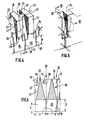
- - la figure 1 est une vue partielle, en perspective, avec arrachements, d'une forme de réalisation du dispositif d'extrusion selon l'invention;
- - les fig. 2 et 3 sont deux vues partielles, respectivement de dessous et de dessus, du dispositif de la figure 1, montrant les orifices de sortie et d'entrée destinés au passage de la pâte céramique;
- - la figure 4 est une vue partielle, en perspective, d'une barrette élémentaire du dispositif des figures précédentes;
- - la figure 5 est une vue analogue à celle de la figure 4, montrant le rapprochement de deux barrettes semblables;
- - la figure 6 est une vue en coupe selon le plan VI-VI de la figure 5.
- - Figure 1 is a partial perspective view, with parts broken away, of an embodiment of the extrusion device according to the invention;
- - figs. 2 and 3 are two partial views, respectively from below and from above, of the device in FIG. 1, showing the outlet and inlet orifices intended for the passage of the ceramic paste;
- - Figure 4 is a partial perspective view of an elementary bar of the device of the previous figures;
- - Figure 5 is a view similar to that of Figure 4, showing the approximation of two similar bars;
- - Figure 6 is a sectional view along the plane VI-VI of Figure 5.
Dans la forme de réalisation choisie et représentée, le dispositif selon l'invention est constitué d'un ensemble de barrettes, chacune ayant une forme générale parallélépipédique, cet ensemble comprenant des barrettes 10, semblables entre elles, empilées les unes à côté des autres, entre deux barrettes d'extrémité 11 et 12.In the embodiment chosen and shown, the device according to the invention consists of a set of bars, each having a generally parallelepiped shape, this
L'assemblage de ces barrettes forme une plaque P ayant en plan une forme rectangulaire ou carrée, la cohésion de cet assemblage étant assurée au moyen de deux broches non représentées traversant des alésages 13 ménagés à chacune des extrémités desdites barrettes pour le positionnement de celles-ci et comportant des moyens de rapprochement et de serrage de ces barrettes.The assembly of these bars forms a plate P having in plan a rectangular or square shape, the cohesion of this assembly being ensured by means of two pins not shown passing through
Chaque barrette 10, et chacune des barrettes d'extrémité 11 et 12, présente une section transversale rectangulaire, et comporte une face supérieure 15, une face inférieure 16 et deux faces verticales 17 et 18.Each
Sur chaque face verticale 17, 18 des barrettes centrales 10 et sur les faces verticales internes des barrettes d'extrémité 11 et 12, est ménagée une série d'encoches 20, réalisées par exemple par fraisage, chaque encoche 20 présentant entre deux côtés 21, perpendiculaires aux faces 17, 18, un fond oblique 22, incliné par rapport à ces faces, l'encoche 20 ayant une profondeur variable entre une valeur maximale sur la face supérieure 15 et une valeur nulle à une distance d de la face inférieure 16, en un point situé au-dessus de cette face.On each
Sur chaque barrette 10, les encoches 20, régulièrement réparties sont disposées en vis-à-vis d'une face 17, 18 à l'autre, les fonds de deux encoches opposées 20 laissant subsister entre eux une bande étroite de matière 23 sur la face supérieure 15. Les encoches 20 des barrettes adjacentes se correspondent.On each
Sur l'une des faces verticales de la barrette, sur la face 17 dans cet exemple, est réalisé à la partie inférieure de chaque barrette 10, un décrochement 25, ménageant une face plane 26, en retrait par rapport à la face 17 d'une profondeur e, et parallèle à cette face. Ce décrochement est situé à une distance D (voir la figure 6) de la face inférieure 16 de la barrette, D étant supérieur à d.On one of the vertical faces of the bar, on the
En outre, suivant le plan vertical de symétrie de chaque encoche, est ménagée dans la face inférieure 16 de chaque barrette, à l'exception des barrettes et des encoches d'extrémité, une saignée 28, d'une largeur l égale à e et d'une hauteur sensiblement égale à D (fig. 4, 5 et 6), de manière à chevaucher le fond de cette encoche.In addition, along the vertical plane of symmetry of each notch, is formed in the
Ainsi, lors de l'assemblage des barrettes 10 entre les barrettes d'extrémité 11 et 12, pour former une plaque P, on obtient un bloc dans l'une des faces (réalisée par juxtaposition des faces 15) duquel débouchent des ouvertures 30 formées chacun par la réunion de deux encoches 20 de deux barrettes adjacentes (fig. 3), tandis que dans l'autre face (juxtaposition des faces 16) s'ouvre un réseau de fentes 31, perpendiculaires entre elles, ménagé par les saignées 28 et les décrochements 25, la fente dans ce dernier cas étant formée par les faces 26 et les faces 18 adjacentes (fig. 6).Thus, during the assembly of the
Les barrettes d'extrémité 11 et 12 présentent par rapport aux barrettes courantes 10 du côté de la face inférieure 16 et à chaque extrémité un excès de longueur correspondant à l'épaisseur d'une fente 31 à la périphérie de la structure alvéolaire. En appliquant un élément de ceinture (non représenté) sur les barrettes assemblées, on ferme l'extrémité des fentes formées par les décrochements 25 par une fente périphérique 31a qui peut être éventuellement plus épaisse que les fentes de réseau 31. De même, les fentes 31b ménagées au contact des barrettes d'extrémité 11 et 12 peuvent présenter une plus grande épaisseur correspondant à l'enveloppe périphérique de la structure alvéolaire.The
Les ouvertures 30 et ces fentes 31 communiquent entre elles. Ainsi, de la pâte céramique repoussée à travers les ouvertures 30, par tout moyen approprié, se trouve extrudée par le réseau quadrillé des fentes 31, pour former la structure alvéolaire recherchée.The
L'outillage selon la présente invention est tout particulièrement convenable pour l'extrusion d'éléments destinés à être soumis à de fortes températures et pressions, par exemple d'éléments de filtres pour métaux liquides, auquel cas ces éléments sont formés de matériaux réfractaires.The tooling according to the present invention is very particularly suitable for the extrusion of elements intended to be subjected to high temperatures and pressures, for example filter elements for liquid metals, in which case these elements are formed of refractory materials.
Bien entendu, la présente invention n'est pas limitée aux modes de réalisation décrits et représentés et elle est susceptible de nombreuses variantes accessibles à l'homme de l'art, sans que l'on ne s'écarte de l'esprit de l'invention. Ainsi, en cas d'obturation d'une ou plusieurs des fentes 31, il est aisé de procéder à leur débouchage après démontage du bloc P sans risquer d'endommager les fentes, et ceci même lorsque le matériau inclus dans ces fentes est très résistant après séchage.Of course, the present invention is not limited to the embodiments described and shown and it is capable of numerous variants accessible to those skilled in the art, without departing from the spirit of the invention. 'invention. Thus, if one or more of the
Claims (6)
Applications Claiming Priority (2)
| Application Number | Priority Date | Filing Date | Title |
|---|---|---|---|
| FR8707039 | 1987-05-20 | ||
| FR8707039A FR2615438B1 (en) | 1987-05-20 | 1987-05-20 | DEVICE FOR EXTRUDING ALVEOLAR CERAMICS |
Publications (1)
| Publication Number | Publication Date |
|---|---|
| EP0294262A1 true EP0294262A1 (en) | 1988-12-07 |
Family
ID=9351252
Family Applications (1)
| Application Number | Title | Priority Date | Filing Date |
|---|---|---|---|
| EP88401194A Withdrawn EP0294262A1 (en) | 1987-05-20 | 1988-05-18 | Apparatus for extruding alveolar ceramic articles |
Country Status (13)
| Country | Link |
|---|---|
| EP (1) | EP0294262A1 (en) |
| JP (1) | JPS6453809A (en) |
| KR (1) | KR880013668A (en) |
| CN (1) | CN88102964A (en) |
| AU (1) | AU1588188A (en) |
| BR (1) | BR8802415A (en) |
| DK (1) | DK274188A (en) |
| FI (1) | FI882374A (en) |
| FR (1) | FR2615438B1 (en) |
| IL (1) | IL86428A0 (en) |
| NO (1) | NO882164L (en) |
| PT (1) | PT87532A (en) |
| ZA (1) | ZA883311B (en) |
Families Citing this family (1)
| Publication number | Priority date | Publication date | Assignee | Title |
|---|---|---|---|---|
| JP4956045B2 (en) * | 2006-04-28 | 2012-06-20 | ケイミュー株式会社 | Extrusion mold |
Citations (4)
| Publication number | Priority date | Publication date | Assignee | Title |
|---|---|---|---|---|
| US3837783A (en) * | 1972-10-10 | 1974-09-24 | Corning Glass Works | Extrusion die |
| US3923444A (en) * | 1974-05-03 | 1975-12-02 | Ford Motor Co | Extrusion die |
| US4343604A (en) * | 1979-10-15 | 1982-08-10 | Ceraver | Die for extruding ceramic material to form a body of cellular structure, and a method of obtaining said die |
| US4468365A (en) * | 1982-08-19 | 1984-08-28 | Corning Glass Works | Extrusion dies for thin wall substrates |
-
1987
- 1987-05-20 FR FR8707039A patent/FR2615438B1/en not_active Expired - Fee Related
-
1988
- 1988-05-10 AU AU15881/88A patent/AU1588188A/en not_active Abandoned
- 1988-05-10 ZA ZA883311A patent/ZA883311B/en unknown
- 1988-05-18 IL IL86428A patent/IL86428A0/en unknown
- 1988-05-18 EP EP88401194A patent/EP0294262A1/en not_active Withdrawn
- 1988-05-18 NO NO882164A patent/NO882164L/en unknown
- 1988-05-18 BR BR8802415A patent/BR8802415A/en unknown
- 1988-05-19 PT PT87532A patent/PT87532A/en not_active Application Discontinuation
- 1988-05-19 FI FI882374A patent/FI882374A/en not_active Application Discontinuation
- 1988-05-19 DK DK274188A patent/DK274188A/en not_active Application Discontinuation
- 1988-05-19 CN CN198888102964A patent/CN88102964A/en active Pending
- 1988-05-19 JP JP63120800A patent/JPS6453809A/en active Pending
- 1988-05-20 KR KR1019880006043A patent/KR880013668A/en not_active Application Discontinuation
Patent Citations (4)
| Publication number | Priority date | Publication date | Assignee | Title |
|---|---|---|---|---|
| US3837783A (en) * | 1972-10-10 | 1974-09-24 | Corning Glass Works | Extrusion die |
| US3923444A (en) * | 1974-05-03 | 1975-12-02 | Ford Motor Co | Extrusion die |
| US4343604A (en) * | 1979-10-15 | 1982-08-10 | Ceraver | Die for extruding ceramic material to form a body of cellular structure, and a method of obtaining said die |
| US4468365A (en) * | 1982-08-19 | 1984-08-28 | Corning Glass Works | Extrusion dies for thin wall substrates |
Also Published As
| Publication number | Publication date |
|---|---|
| BR8802415A (en) | 1988-12-13 |
| PT87532A (en) | 1989-05-31 |
| FR2615438B1 (en) | 1991-08-23 |
| NO882164L (en) | 1988-11-21 |
| FR2615438A1 (en) | 1988-11-25 |
| JPS6453809A (en) | 1989-03-01 |
| AU1588188A (en) | 1988-11-24 |
| FI882374A0 (en) | 1988-05-19 |
| DK274188A (en) | 1988-11-21 |
| NO882164D0 (en) | 1988-05-18 |
| KR880013668A (en) | 1988-12-21 |
| CN88102964A (en) | 1988-12-28 |
| ZA883311B (en) | 1988-11-14 |
| IL86428A0 (en) | 1988-11-15 |
| FI882374A (en) | 1988-11-21 |
| DK274188D0 (en) | 1988-05-19 |
Similar Documents
| Publication | Publication Date | Title |
|---|---|---|
| EP1201420B1 (en) | Sound absorbing panel particularly for aircraft engine | |
| EP0573355B1 (en) | Connecting block for profiled bars and bar assembly using same | |
| FR2817994A1 (en) | SANDWICH ACOUSTIC PANEL | |
| WO1998033716A1 (en) | Material handling pallet | |
| FR2727542A1 (en) | CARD INCORPORATING AT LEAST ONE ELECTRONIC ELEMENT | |
| EP3180790B1 (en) | Basket for transport and/or storage of radioactive materials | |
| FR2799338A1 (en) | SET OF MODULES FOR THE PRODUCTION OF FUSE BOXES | |
| EP0294262A1 (en) | Apparatus for extruding alveolar ceramic articles | |
| FR2676994A1 (en) | Light loading platform for the transport of goods | |
| EP0017574B1 (en) | Joint connector for an open-framework structure, and such a structure equipped with such a connector | |
| FR2698436A1 (en) | Mass and heat exchanger with porous plates. | |
| WO1983003318A1 (en) | Kit for making electric circuits | |
| FR3044723A1 (en) | MOUNTING ASSEMBLY WITH INCLINED GROOVES | |
| FR2604246A1 (en) | Modular heat exchanger | |
| WO1989001599A1 (en) | Jet impact heat exchanger | |
| WO1999066214A1 (en) | Fluidic oscillator, part designed to be incorporated in a fluidic oscillator and method for making such a fluidic oscillator | |
| FR2826310A1 (en) | TOOLS FOR THERMOFORMING A WEB OF SYNTHETIC MATERIAL (S) | |
| FR2656514A1 (en) | MATTRESS AND METHOD FOR PRODUCING THE SAME | |
| LU83967A1 (en) | LAYOUT OF CONSTRUCTION ELEMENTS | |
| EP0295976A1 (en) | Tool for extruding alveolar ceramic articles | |
| FR2974588A1 (en) | Insulating formwork block for constructing concrete building wall, has plates with tenons and mortises dimensioned to have tight fit during engagement with mortises and tenons of another block, and spacer blades acting as concrete support | |
| EP0294261A1 (en) | Apparatus for extruding alveolar structural bodies from ceramic | |
| FR2519579A1 (en) | Heat exchanger plates made by assembling polymer modules - where module ends are placed in mould filled with polymer to join modules together | |
| FR2467369A1 (en) | HEAT EXCHANGER WITH PLATES AND BARS WITH INTEGRATED HEADS | |
| FR2632710A1 (en) | IMPROVEMENTS TO PLASTIC CUTTING ELEMENTS |
Legal Events
| Date | Code | Title | Description |
|---|---|---|---|
| PUAI | Public reference made under article 153(3) epc to a published international application that has entered the european phase |
Free format text: ORIGINAL CODE: 0009012 |
|
| AK | Designated contracting states |
Kind code of ref document: A1 Designated state(s): AT BE CH DE ES FR GB GR IT LI LU NL SE |
|
| STAA | Information on the status of an ep patent application or granted ep patent |
Free format text: STATUS: THE APPLICATION IS DEEMED TO BE WITHDRAWN |
|
| 18D | Application deemed to be withdrawn |
Effective date: 19890608 |