EP0573355B1 - Connecting block for profiled bars and bar assembly using same - Google Patents
Connecting block for profiled bars and bar assembly using same Download PDFInfo
- Publication number
- EP0573355B1 EP0573355B1 EP93401410A EP93401410A EP0573355B1 EP 0573355 B1 EP0573355 B1 EP 0573355B1 EP 93401410 A EP93401410 A EP 93401410A EP 93401410 A EP93401410 A EP 93401410A EP 0573355 B1 EP0573355 B1 EP 0573355B1
- Authority
- EP
- European Patent Office
- Prior art keywords
- unit
- holes
- face
- bars
- faces
- Prior art date
- Legal status (The legal status is an assumption and is not a legal conclusion. Google has not performed a legal analysis and makes no representation as to the accuracy of the status listed.)
- Expired - Lifetime
Links
- 239000007787 solid Substances 0.000 claims description 14
- 238000010079 rubber tapping Methods 0.000 claims description 6
- 230000002093 peripheral effect Effects 0.000 claims description 2
- 238000010276 construction Methods 0.000 description 7
- 230000006978 adaptation Effects 0.000 description 4
- 238000003754 machining Methods 0.000 description 4
- 238000009434 installation Methods 0.000 description 2
- 238000000034 method Methods 0.000 description 2
- 230000035515 penetration Effects 0.000 description 2
- 238000009825 accumulation Methods 0.000 description 1
- 230000000712 assembly Effects 0.000 description 1
- 238000000429 assembly Methods 0.000 description 1
- 230000004323 axial length Effects 0.000 description 1
- 238000005520 cutting process Methods 0.000 description 1
- 230000005611 electricity Effects 0.000 description 1
- 230000002349 favourable effect Effects 0.000 description 1
- 238000004519 manufacturing process Methods 0.000 description 1
- 239000000463 material Substances 0.000 description 1
- 238000012986 modification Methods 0.000 description 1
- 230000004048 modification Effects 0.000 description 1
- 238000000465 moulding Methods 0.000 description 1
- 238000004080 punching Methods 0.000 description 1
- 238000011084 recovery Methods 0.000 description 1
Images


Classifications
-
- F—MECHANICAL ENGINEERING; LIGHTING; HEATING; WEAPONS; BLASTING
- F16—ENGINEERING ELEMENTS AND UNITS; GENERAL MEASURES FOR PRODUCING AND MAINTAINING EFFECTIVE FUNCTIONING OF MACHINES OR INSTALLATIONS; THERMAL INSULATION IN GENERAL
- F16B—DEVICES FOR FASTENING OR SECURING CONSTRUCTIONAL ELEMENTS OR MACHINE PARTS TOGETHER, e.g. NAILS, BOLTS, CIRCLIPS, CLAMPS, CLIPS OR WEDGES; JOINTS OR JOINTING
- F16B7/00—Connections of rods or tubes, e.g. of non-circular section, mutually, including resilient connections
- F16B7/18—Connections of rods or tubes, e.g. of non-circular section, mutually, including resilient connections using screw-thread elements
- F16B7/187—Connections of rods or tubes, e.g. of non-circular section, mutually, including resilient connections using screw-thread elements with sliding nuts or other additional connecting members for joining profiles provided with grooves or channels
-
- E—FIXED CONSTRUCTIONS
- E04—BUILDING
- E04B—GENERAL BUILDING CONSTRUCTIONS; WALLS, e.g. PARTITIONS; ROOFS; FLOORS; CEILINGS; INSULATION OR OTHER PROTECTION OF BUILDINGS
- E04B2/00—Walls, e.g. partitions, for buildings; Wall construction with regard to insulation; Connections specially adapted to walls
- E04B2/74—Removable non-load-bearing partitions; Partitions with a free upper edge
- E04B2/76—Removable non-load-bearing partitions; Partitions with a free upper edge with framework or posts of metal
-
- F—MECHANICAL ENGINEERING; LIGHTING; HEATING; WEAPONS; BLASTING
- F16—ENGINEERING ELEMENTS AND UNITS; GENERAL MEASURES FOR PRODUCING AND MAINTAINING EFFECTIVE FUNCTIONING OF MACHINES OR INSTALLATIONS; THERMAL INSULATION IN GENERAL
- F16B—DEVICES FOR FASTENING OR SECURING CONSTRUCTIONAL ELEMENTS OR MACHINE PARTS TOGETHER, e.g. NAILS, BOLTS, CIRCLIPS, CLAMPS, CLIPS OR WEDGES; JOINTS OR JOINTING
- F16B2200/00—Constructional details of connections not covered for in other groups of this subclass
- F16B2200/40—Clamping arrangements where clamping parts are received in recesses of elements to be connected
- F16B2200/403—Threaded clamping parts
-
- Y—GENERAL TAGGING OF NEW TECHNOLOGICAL DEVELOPMENTS; GENERAL TAGGING OF CROSS-SECTIONAL TECHNOLOGIES SPANNING OVER SEVERAL SECTIONS OF THE IPC; TECHNICAL SUBJECTS COVERED BY FORMER USPC CROSS-REFERENCE ART COLLECTIONS [XRACs] AND DIGESTS
- Y10—TECHNICAL SUBJECTS COVERED BY FORMER USPC
- Y10T—TECHNICAL SUBJECTS COVERED BY FORMER US CLASSIFICATION
- Y10T403/00—Joints and connections
- Y10T403/46—Rod end to transverse side of member
- Y10T403/4602—Corner joint
Definitions
- the present invention relates to the field of connection and assembly of profiled bars and it relates, more specifically, to the field of profiled bars with polygonal cross-section and comprising, on at least one of their longitudinal faces, a open T-slot.
- Such means suffer from all the above drawbacks and cannot be considered to offer a rapid, safe and efficient assembly and erection capacity. Such means also pose practical problems when the assembly must take place on a site where an auxiliary energy, such as electricity, is lacking for the supply of the machining equipment.
- the object of the invention is to overcome the above drawbacks by proposing a single connection and assembly block for different connection modes capable of occurring between profiled bars, such as for example an end-to-end connection, a link in two parallel planes or a link in the same plane.
- the object of the invention is designed to also allow the constitution of assembly nodes from a number of bars greater than two or even bars whose cross section represents an integer multiple of the same construction module of based.
- Another object of the invention is to provide a connection block requiring no prior machining both on itself and on the bars to be assembled and making it possible to make a quick, efficient, positive connection, without additional energy and by simple interlocking and screwing.
- Another object of the invention is to propose a block of connection and assembly which can be obtained easily by molding, for example in shell, without requiring significant operations to resume secondary machining.
- An additional object of the invention is to provide a connection and assembly block which fits into the profile of the bars to be assembled, so as to allow connection nodes of the same size as the cross section of the bars and offering, in addition, an aesthetic character which, if it is not fundamental for the technical characteristics of the connection and the assembly carried out, nevertheless allows the construction and the erection of structures of taut and pure lines, susceptible to offer flat faces, suitable in particular for constituting support benches for the construction of sets of machines or installations of modular or non-modular nature.
- connection and assembly block according to the invention lies in the fact that its implementation and adaptation can be carried out quickly by personnel not specially highly qualified, which makes it possible to reduce the overall cost of creation. , realization, construction of a structure based on profiled bars.
- connection and assembly block for profiled bars according to the invention is characterized by the characterizing part of claim 1.
- the invention also relates to an assembly of profiled bars produced by means of at least one block of the above type.
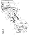
- Fig. 1 is an exploded perspective of a node for assembling and connecting two profiled bars, from a block according to the invention.
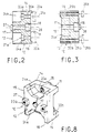
- Figs. 2 and 3 are sections taken respectively on planes II-II and III-III of FIG. 1.
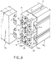
- Figs. 4, 5, 6 and 7 are perspectives illustrating four examples of assembly of profiled bars by means of the block according to the invention.
- Fig. 8 is a perspective similar to FIG. 1 illustrating an alternative embodiment.
- Fig. 9 is an exploded perspective of another embodiment.
- connection and assembly block is designed to allow the constitution of assembly nodes between elements of profiled bars, such as B 1 and B 2 , having an identical construction and structure or alike.
- each bar B 1 or B 2 is of the cross-section type, polygonal, preferably square or rectangular and comprises, on at least one face lateral 1 , at least one inverted T-shaped groove 2 , the inlet 3 of which is delimited by two rectilinear edges 4 facing each other and having a thickness e , preferably, constant.
- the bars B 1 and B 2 may have only one T-groove or, as illustrated in the drawings, a T-groove for each of the longitudinal faces, or even several for each face.
- Each bar B 1 or B 2 may also comprise, during manufacture or by subsequent recovery, at least one passage 5 , for example axial, of constant cross section.
- connection and assembly block consists of a solid body 10 , of generally rectangular parallelepiped shape, defining two lateral faces 11 and 12 having a geometric conformation which is preferably the same as the cross section of bar B 1 or bar B 2 .
- the solid body 10 thus has a periphery consisting of four faces 13 to 16 meeting at a right angle in the example illustrated and defining the thickness of the solid body 10 .
- Figs. 2 and 3 show in more detail that the solid body 10 is pierced in its thickness and in its center with a through bore 17 which opens on the face 12 by a counterbore 18 .
- the through bore 17 is formed according to coordinates which allow coincidence with the passage 5 , when the block is placed at the end of the bar B 1 or B 2 .
- the through bore is made in the center of the cross section of the block.
- the bore 17 and the counterbore 18 are reserved for mounting a self-tapping screw with head 19 intended to ensure possible fixing, at the end of the bar element B 1 , for example, by self-tapping engagement of the screw 19 in the axial passage 5 .
- the lateral face 11 of the solid body 10 is then applied to the transverse face at the end of the bar element B 1 .
- the solid body 10 is pierced in two orthogonal planes, such as the planes II and III, with two series of through holes 20a and 20b which, in the example illustrated, are provided, for each series, at equal distance, on either side of the axial bore 17 .
- the holes 20a of the first series are preferably reserved for mounting screws 21a cooperating beyond the face 12 with one or more lardon nuts 22a , the conformation of which is chosen so that they can be engaged inside a groove in T 2 behind the longitudinal edges 4 .
- the lardon nuts 22a can thus be provided individually for each screw 20a or, on the contrary, be produced in the form of a single bar having two internal threads capable of receiving the two screws 21a simultaneously.
- the holes 20a open through counterbores 23a in access openings 24a which are formed in the solid block 10 , from the lateral face 12 opposite to that offering the counterbore 18 of the central bore 17 , for s '' open on the transverse faces 14 and 16 .
- the holes 20b of the second series orthogonal to the first are, in a first example, constituted by threaded through passages which open on the two lateral faces 11 and 12 and which are intended to receive screws 25b whose axial length is, in an exemplary embodiment, close to but at most equal to the thickness of the solid body 10 .
- At least one of the lateral faces 11 , 12 and, preferably, both, has, in relief and in alignment with the corresponding contour faces, projections whose width is equal to the clearance of near penetration, at the width of the entrances 3 and whose thickness is equal to the thickness e .
- the projections, bearing the references 26 and 27 , respectively for the faces 11 and 12 are constituted by prismatic masses which are preferably two in number for each face, being aligned with one another and formed in correspondence with the series of holes. , that is to say with the series of holes 20a for the face 11 and with the series of holes 20b for the face 12 and being centered on the planes II and III.
- the face 11 devoid of the clearances 24a has notches 28 of conjugate conformation to the prismatic masses 27 and formed in a manner homologous to the latter.
- the block described above makes it possible to carry out different types of assembly, an example of which is illustrated in FIG. 1 .
- the block 10 can be adapted on the bar element B 1 by being placed at the end of this element, so that an angular connection is established by the engagement of the projection (s) 27 in the corresponding grooves 2 , when for example the bar element B 1 has a groove 2 on each of its longitudinal faces.
- the axial connection is ensured by mounting the screw 19 in the hole 17 , so as to ensure engagement by self-tapping in the passage 5 allowing effective immobilization tightening. A positive axial and angular connection is thus established.
- the assembly with the bar element B 2 involves the engagement of the bar or lardon nuts 22a in the T-groove offered by the face of the element B 2 opposite.
- the prismatic masses 26 can then be engaged in this groove, so that the screws 21a can cooperate with the bar or the lardon nuts 22a to tighten the lateral face 11 of the block 10 against the corresponding longitudinal face of the bar element B 2 with effective nipping of the edges 4 between the lardon nuts 22a and the face 11 .
- An additional positive axial locking can be obtained by screwing the screws 25b into the holes 20b , so that the corresponding ends, projecting from the face 11 can act like bowl screws by partial punching and tightening on the longitudinal face. bar element B 2 .
- the assembly node thus produced, has the same size as the cross section of the bar elements B 1 and B 2 and that it can be obtained by simple interlocking and screwing operations.
- the screws 21a are easily accessible via the clearances 24a and can thus be driven in rotation over a partial angular range, but nevertheless significant, due to the opening or the outlet of each clearance 24a on the transverse faces 14 and 16 . It is the same for the screws 25b accessible directly from the T-shaped grooves 2 .
- Fig. 4 shows another example of possible connection and assembly between the elements B 1 and B 2 , then arranged in two parallel planes.
- the block 10 can be mounted for example on the bar element B 2 , by means of the screws 25b whose length, greater than the thickness of the block, allows cooperation with lardon nuts 29b ( Fig. 3 ) which are engaged in the groove 2 of the corresponding face of the bar B 2 .
- the lardon nuts 29b can also be replaced by a bar having two threaded holes.
- the tapped holes 20b are replaced by smooth holes or the screws 25b are chosen with a diameter just smaller than that of the holes 20b to allow free axial movement.
- the bar element B 1 is then fixed to the block 10 by means of the screws 21a cooperating with the lardon nuts 22a .
- the screw 19 is not mounted. It could, however, be envisaged, in certain cases, to ensure the connection of the body 10 on the bar element B 2 , only by means of the screw 19 brought to cooperate with a lardon nut engaged in the groove 2 , by which the block is angularly immobilized by penetration of the prismatic masses 27 .
- the solid block 10 makes it possible to constitute a knot whose size, apart from the desired plane shift between the bar elements B 1 and B 2 , fits exactly in the cross section of said elements.
- Fig. 5 shows an example of implementation of the object of the invention to establish the connection between a bar element B 1 and two bar elements B 2 arranged side by side.
- a node is obtained by then using two connection blocks 10 which are mounted at the end of the two bar elements B 2 , as said above, so that they can then be fixed by the two extreme screws 21a on the bar element B 1 .
- the two bar elements B 2 can be independent and separate or even constitute a single bar element whose transverse module is twice the unitary element described with reference to FIG. 1 .
- Fig. 6 shows another variant, from two blocks 10 arranged at the end of two simple bar elements B 2 or a double bar element B 2 , to establish a connection node with a bar element B 1 having in section transverse right a double module of the element, according to FIG. 1 , and offering on a longitudinal face two inverted T-grooves 2 .
- the references given in FIG. 6 make it possible to determine the mounting orientation of the two bodies 10 which are first of all adapted at the end of the bar element or elements B 2 .
- Fig. 7 shows another example of assembly in which the bar elements B 1 and B 2 , of the type of FIG. 1 , must be assembled end to end.
- each bar element receives a solid body 10 mounted by means of the screw 19 , so that each of them is applied at the end of the corresponding bar element by the face 12 .
- each solid body 10 is carried out with a 90 ° offset, so as to make the prismatic masses 26 of one of the solid bodies 10 cooperate, by relative reciprocal engagement, with the notches 28 of the solid body opposite. .
- the bar elements B 1 and B 2 are then placed end to end in order to be linked by the installation of the screws 21a screwed into the holes 20b .
- Fig. 8 shows an alternative embodiment consisting in providing clearances 30 b in the face 11 by adopting an offset of 90 ° relative to the clearances 24a , so that the clearances 30b open on the transverse faces 13 and 15 .
- FIG. 4 shows an alternative embodiment consisting in providing in the face 11 , for example, a recess 40 leaving a peripheral border 41 which is favorable to the establishment of good support of the face 11 on the longitudinal face of the element B 1 , for example.
- the holes 20b may open into negative impressions 42 formed in the bottom of the recess 40 and, for example hexagonal, to receive captive nuts crimped for mounting the screws 25b .
- Fig. 9 shows an alternative embodiment of the object of the invention adapted to the connection of bars B 1 and B 2 which have several grooves 2 on at least one longitudinal face and, preferably but not exclusively, two on each of them .
- each sector or quadrant of the cross section, including a longitudinal edge has the same conformation as that of the example in FIG. 1 .
- the intersection of the planes P 1 and P 2 passing through the grooves, situated on either side of the same edge defines the axis of a passage 50 similar to the passage 5 .
- connection and assembly block 10 then comprises, on the basis of the initial example but in adaptation to the cross section of the bars B 1 and B 2 of the example according to the Fig. 2 , two double series of through holes 20a 1 and 20a 2 provided according to plans II 1 and II 2 and 20b 1 and 20b 2 provided according to plans III 1 and III 2 .
- the holes 20a 1 and 20a 2 correspond to the clearances 24a 1 and 24a 2 , as well as the prismatic masses 26 1 and 26 2 .
- the holes 20b 1 and 20b 2 correspond to the prismatic masses 27 1 and 27 2 , as well as the notches 28 1 and 28 2 .
- the block 10 according to this example also comprises through bores 60 which are arranged to be placed in coincidence with the passages 50 and allow the mounting of screws 19 engaging by self-tapping in said passages.
Description
La présente invention est relative au domaine de la liaison et de l'assemblage de barres profilées et elle vise, plus spécifiquement, le domaine des barres profilées à section droite transversale polygonale et comportant, sur l'une au moins de leur face longitudinale, une rainure en T ouverte.The present invention relates to the field of connection and assembly of profiled bars and it relates, more specifically, to the field of profiled bars with polygonal cross-section and comprising, on at least one of their longitudinal faces, a open T-slot.
On connaît depuis quelques temps déjà l'existence de barres profilées à section circulaire ou polygonale qui sont réalisées en de nombreux matériaux différents et qui sont destinées à permettre la construction et l'érection de structures diverses pouvant aller de l'échafaudage ou analogue à des ossatures porteuses à caractère temporaire ou définitif, jusqu'à des bâtis de machines à caractère modulaire ou non.We have known for some time already the existence of profiled bars of circular or polygonal section which are made of many different materials and which are intended to allow the construction and erection of various structures which can range from scaffolding or the like load-bearing structures of a temporary or permanent nature, up to machine frames of a modular or non-modular nature.
Si de telles barres profilées présentent, sans aucun doute, des avantages de résistance mécanique, de coût économique relativement faible et de facilité d'adaptation, notamment par coupe à longueur voulue, les méthodes d'assemblage jusqu'à présent connues ne peuvent pas être considérées comme donnant satisfaction sur plusieurs points.If such profiled bars undoubtedly have the advantages of mechanical strength, relatively low economic cost and ease of adaptation, in particular by cutting to desired length, the assembly methods hitherto known cannot be considered satisfactory on several points.
En règle générale, il est proposé d'avoir recours à des sortes de noix constituées par des demi-coquilles assemblables qui sont conçues pour enserrer deux barres devant être assemblées, pour former avec ces dernières un noeud de liaison.As a general rule, it is proposed to have recourse to kinds of nuts constituted by assemblable half-shells which are designed to grip two bars to be assembled, to form with the latter a connecting node.
De telles noix ne sont pas esthétiquement convenables, techniquement adaptées à tous les modes d'assemblage et, par conséquent, ne peuvent pas être mises en oeuvre dans toutes les applications, en particulier lorsque des assemblages bout à bout et/ou dans un même plan doivent être assurés.Such nuts are not aesthetically suitable, technically suitable for all assembly methods and, therefore, cannot be used in all applications, in particular when end-to-end assemblies and / or in the same plane must be insured.
Un autre inconvénient devant être porté au compte de telles structures en demi-coquilles enserrant les barres, tient au fait que leur forme enveloppant les barres confère au noeud d'assemblage réalisé un encombrement dans les trois plans qui représentent le plus souvent une sujétion importante, lorsqu'il convient de définir avec les barres des plans rigoureux servant, par exemple, de bancs de fixation pour des appareillages divers ou pour la construction de modules fonctionnels.Another drawback to be taken into account for such half-shell structures enclosing the bars, is that their shape enveloping the bars gives the assembly knot a space requirement in the three planes which most often represent a significant subjection, when rigorous serving plans are to be defined with the bars, for example, fixing benches for various devices or for the construction of functional modules.
Un autre inconvénient connu de ces moyens de liaison réside dans l'impossibilité de constituer de façon pratique, efficace et certaine, des liaison dites à fixation positive, à même de s'opposer à tout risque de glissement relatif d'une barre par rapport à l'autre.Another known drawback of these connecting means lies in the impossibility of constituting in a practical, efficient and certain manner, so-called positively attached connections, capable of opposing any risk of relative sliding of a bar relative to the other.
On a certainement proposé aussi des moyens plus simples de liaison de barres en prévoyant entre les faces à lier des opérations d'usinage Longues et coûteuses permettant d'insérer des moyens de fixation par collier, vis, tirant, etc... ou d'interposer entre Les barres une plaque fixée à celles-ci par des boulons (DE-U-8 604 195).Simpler means of connecting bars have certainly also been proposed by providing long and costly machining operations between the faces to be bonded, making it possible to insert fixing means by collar, screw, tie rod, etc. interpose between the bars a plate fixed to them by bolts (DE-U-8 604 195).
De tels moyens souffrent de tous les inconvénients précédents et ne peuvent pas être considérés comme offrant une capacité d'assemblage et d'érection rapide, sûre, efficace. De tels moyens posent, par ailleurs, des problèmes pratiques lorsque L'assemblage doit intervenir sur un site où une énergie d'appoint, telle que l'électricité, fait défaut pour l'alimentation des appareils d'usinage.Such means suffer from all the above drawbacks and cannot be considered to offer a rapid, safe and efficient assembly and erection capacity. Such means also pose practical problems when the assembly must take place on a site where an auxiliary energy, such as electricity, is lacking for the supply of the machining equipment.
L'objet de l'invention est de pallier les inconvénients ci-dessus en proposant un bloc de liaison et d'assemblage unique pour différents modes de liaison susceptibles d'intervenir entre des barres profilées, tels que par exemple une liaison bout à bout, une liaison dans deux plans parallèles ou une liaison dans un même plan.The object of the invention is to overcome the above drawbacks by proposing a single connection and assembly block for different connection modes capable of occurring between profiled bars, such as for example an end-to-end connection, a link in two parallel planes or a link in the same plane.
L'objet de l'invention est conçu pour permettre aussi la constitution de noeuds d'assemblage à partir d'un nombre de barres supérieur à deux ou encore de barres dont la section droite transversale représente un multiple entier d'un même module constructif de base.The object of the invention is designed to also allow the constitution of assembly nodes from a number of bars greater than two or even bars whose cross section represents an integer multiple of the same construction module of based.
Un autre objet de l'invention, est de proposer un bloc de liaison ne nécessitant aucun usinage préalable tant sur lui-même que sur les barres à assembler et permettant de réaliser une liaison rapide, efficace, positive, sans appoint d'énergie et par simple emboîtement et vissage.Another object of the invention is to provide a connection block requiring no prior machining both on itself and on the bars to be assembled and making it possible to make a quick, efficient, positive connection, without additional energy and by simple interlocking and screwing.
Un autre objet de l'invention est de proposer un bloc de liaison et d'assemblage qui puisse être obtenu facilement par moulage, par exemple en coquille, sans exiger d'opérations importantes de reprise d'usinage secondaire.Another object of the invention is to propose a block of connection and assembly which can be obtained easily by molding, for example in shell, without requiring significant operations to resume secondary machining.
Un objet supplémentaire de l'invention est de proposer un bloc de liaison et d'assemblage qui s'inscrive dans le profil des barres à assembler, de manière à permettre l'obtention de noeuds de liaison de même encombrement que la section droite transversale des barres et offrant, supplémentairement, un caractère esthétique qui, s'il n'est pas fondamental pour les caractéristiques techniques de la liaison et de l'assemblage réalisés, permet néanmoins la construction et l'érection de structures de lignes tendues et pures, susceptibles d'offrir des faces planes, aptes notamment à constituer des bancs de soutien pour la construction d'ensembles de machines ou d'installations à caractère modulaire ou non.An additional object of the invention is to provide a connection and assembly block which fits into the profile of the bars to be assembled, so as to allow connection nodes of the same size as the cross section of the bars and offering, in addition, an aesthetic character which, if it is not fundamental for the technical characteristics of the connection and the assembly carried out, nevertheless allows the construction and the erection of structures of taut and pure lines, susceptible to offer flat faces, suitable in particular for constituting support benches for the construction of sets of machines or installations of modular or non-modular nature.
Un avantage supplémentaire attaché au bloc de liaison et d'assemblage selon l'invention réside dans le fait que sa mise en oeuvre et son adaptation peuvent être réalisées rapidement par un personnel non spécialement hautement qualifié, ce qui permet de réduire le coût global de création, de réalisation, de construction d'une structure à base de barres profilées.An additional advantage attached to the connection and assembly block according to the invention lies in the fact that its implementation and adaptation can be carried out quickly by personnel not specially highly qualified, which makes it possible to reduce the overall cost of creation. , realization, construction of a structure based on profiled bars.
Pour atteindre les objectifs ci-dessus, Le bloc de Liaison et d'assemblage pour barres profilées selon L'invention est caractérisé par La partie caractérisante de La revendication 1.To achieve the above objectives, the connection and assembly block for profiled bars according to the invention is characterized by the characterizing part of
L'invention a également pour objet un assemblage de barres profilées réalisé au moyen d'au moins un bloc du type ci-dessus.The invention also relates to an assembly of profiled bars produced by means of at least one block of the above type.
Diverses autres caractéristiques ressortent de la description faite ci-dessous en référence aux dessins annexés qui montrent, à titre d'exemples non limitatifs, des formes de réalisation de l'objet de l'invention.Various other characteristics will emerge from the description given below with reference to the appended drawings which show, by way of nonlimiting examples, embodiments of the subject of the invention.
La Fig. 1 est une perspective éclatée d'un noeud d'assemblage et de liaison de deux barres profilées, à partir d'un bloc conforme à l'invention.Fig. 1 is an exploded perspective of a node for assembling and connecting two profiled bars, from a block according to the invention.
Les Fig. 2 et 3 sont des coupes prises respectivement selon les plans II-II et III-III de la Fig. 1.Figs. 2 and 3 are sections taken respectively on planes II-II and III-III of FIG. 1.
Les Fig. 4, 5, 6 et 7 sont des perspectives illustrant quatre exemples d'assemblage de barres profilées au moyen du bloc selon l'invention.Figs. 4, 5, 6 and 7 are perspectives illustrating four examples of assembly of profiled bars by means of the block according to the invention.
La Fig. 8 est une perspective analogue à la Fig. 1 illustrant une variante de réalisation.Fig. 8 is a perspective similar to FIG. 1 illustrating an alternative embodiment.
La Fig. 9 est une perspective éclatée d'une autre forme de réalisation.Fig. 9 is an exploded perspective of another embodiment.
Selon le premier exemple de réalisation illustré par les Fig. 1 à 3, le bloc de liaison et d'assemblage selon l'invention est conçu pour permettre la constitution de noeuds d'assemblage entre des éléments de barres profilées, tels que B1 et B2, présentant une construction et une structure identiques ou semblables. Dans l'exemple illustré, chaque barre B1 ou B2 est du type à section droite transversale, polygonale, de préférence, carrée ou rectangulaire et comporte, sur au moins une face latérale 1, au moins une rainure en T inversé 2 dont l'entrée 3 est délimitée par deux bords 4 rectilignes se faisant face et présentant une épaisseur e , de préférence, constante. Les barres B 1 et B 2 peuvent ne comporter qu'une seule rainure en T ou, comme cela est illustré aux dessins, une rainure en T pour chacune des faces longitudinales, voire plusieurs pour chaque face. Chaque barre B 1 ou B 2 peut aussi comporter, de fabrication ou par reprise ultérieure, au moins un pasage 5, par exemple axial, de section droite constante.According to the first exemplary embodiment illustrated by FIGS. 1 to 3, the connection and assembly block according to the invention is designed to allow the constitution of assembly nodes between elements of profiled bars, such as B 1 and B 2 , having an identical construction and structure or alike. In the example illustrated, each bar B 1 or B 2 is of the cross-section type, polygonal, preferably square or rectangular and comprises, on at least one face lateral 1 , at least one inverted T-
Le bloc de liaison et d'assemblage selon l'invention est constitué par un corps massif 10, de forme générale parallélèpipèdique rectangle, définissant deux faces latérales 11 et 12 présentant une conformation géométrique qui est, de préférence, la même que la section droite transversale de la barre B 1 ou de la barre B 2 .The connection and assembly block according to the invention consists of a
Le corps massif 10 présente ainsi un pourtour constitué de quatre faces 13 à 16 se réunissant à angle droit dans l'exemple illustré et définissant l'épaisseur du corps massif 10.The
Les Fig. 2 et 3 montrent plus en détail que le corps massif 10 est percé dans son épaisseur et en son centre d'un alésage traversant 17 qui s'ouvre sur la face 12 par un lamage 18. L'alésage traversant 17 est ménagé selon des coordonnées qui permettent une coïncidence avec le passage 5, lorsque le bloc est disposé en bout de la barre B 1 ou B 2 . Dans le cas illustré, l'alésage traversant est pratiqué au centre de la section droite transversale du bloc. L'alésage 17 et le lamage 18 sont réservés au montage d'une vis autotaraudeuse à tête 19 destinée à assurer la fixation possible, en bout de l'élément de barre B 1 , par exemple, par engagement autotaraudé de la vis 19 dans le passage axial 5. Dans un tel cas, la face latérale 11 du corps massif 10 est alors appliquée sur la face transversale en bout de l'élément de barre B 1 . Figs. 2 and 3 show in more detail that the
Suivant une autre disposition constructive, le corps massif 10 est percé selon deux plans orthogonaux, tels que les plans II et III, de deux séries de trous traversants 20a et 20b qui, dans l'exemple illustré, sont prévus, pour chaque série, à égale distance, de part et d'autre de l'alésage axial 17. Les trous 20a de la première série sont, de préférence, réservés au montage de vis 21a coopérant au-delà de la face 12 avec un ou des écrous lardons 22a dont la conformation est choisie pour pouvoir être engagés à l'intérieur d'une rainure en T 2 derrière les bords longitudinaux 4. Les écrous lardons 22a peuvent ainsi être prévus individuels pour chaque vis 20a ou, au contraire, être réalisés sous la forme d'une barrette unique présentant deux taraudages aptes à recevoir simultanément les deux vis 21a. De préférence, les trous 20a débouchent par des lamages 23a dans des dégagements d'accès 24a qui sont ménagés dans le bloc massif 10, à partir de la face latérale 12 opposée à celle offrant le lamage 18 de l'alésage central 17, pour s'ouvrir sur les faces transversales 14 et 16.According to another constructive arrangement, the
Les trous 20b de la seconde série orthogonale à la première sont, dans un premier exemple, constitués par des passages taraudés traversants qui débouchent sur les deux faces latérales 11 et 12 et qui sont destinés à recevoir des vis 25b dont la longueur axiale est, dans un exemple de réalisation, voisine de mais au plus égale à l'épaisseur du corps massif 10.The
Selon une autre disposition constructive, l'une au moins des faces latérales 11, 12 et, de préférence, les deux, comporte, en relief et en alignement avec les faces de contour correspondantes, des saillies dont la largeur est égale, au jeu de pénétration près, à la largeur des entrées 3 et dont l'épaisseur est égale à l'épaisseur e . Les saillies, portant les références 26 et 27, respectivement pour les faces 11 et 12, sont constituées par des masses prismatiques qui sont, de préférence, au nombre de deux pour chaque face en étant alignées entre elles et formées en correspondance des séries de trous, c'est-à-dire avec la série des trous 20a pour la face 11 et avec la série de trous 20b pour la face 12 et en étant centrées sur les plans II et III.According to another constructive arrangement, at least one of the
De préférence, aussi, la face 11 dépourvue des dégagements 24a présente des encoches 28 de conformation conjuguée aux masses prismatiques 27 et ménagées de façon homologue à ces dernières.Preferably, too, the
Le bloc décrit ci-dessus permet de réaliser différents types d'assemblage dont un exemple est illustré par la Fig. 1.The block described above makes it possible to carry out different types of assembly, an example of which is illustrated in FIG. 1 .
Le bloc 10 peut être adapté sur l'élément de barre B 1 en étant placé en bout de cet élément, de telle sorte qu'une liaison angulaire soit établie par l'engagement de la ou des saillies 27 dans les rainures 2 correspondantes, lorsque par exemple l'élément de barre B 1 comporte une rainure 2 sur chacune de ses faces longitudinales. La liaison axiale est assurée par montage de la vis 19 dans le trou 17, de manière à assurer un engagement par autotaraudage dans le passage 5 permettant un serrage d'immobilisation efficace. Une liaison positive axiale et angulaire est ainsi établie.The
L'assemblage avec l'élément de barre B 2 fait intervenir l'engagement de la barrette ou des écrous lardons 22a dans la rainure en T offerte par la face de l'élément B 2 en vis à vis. Les masses prismatiques 26 peuvent alors être engagées dans cette rainure, de manière que les vis 21a puissent coopérer avec la barrette ou les écrous lardons 22a pour serrer la face latérale 11 du bloc 10 contre la face longitudinale correspondante de l'élément de barre B 2 avec pincement efficace des bords 4 entre les écrous lardons 22a et la face 11.The assembly with the bar element B 2 involves the engagement of the bar or
Une liaison angulaire et un blocage axial efficaces entre l'élément de barre B 2 et le bloc 10 sont ainsi établis.An effective angular connection and axial locking between the bar element B 2 and the
Un blocage axial positif supplémentaire peut être obtenu en vissant les vis 25b dans les trous 20b, de telle sorte que les extrémités correspondantes, saillant à partir de la face 11 puissent agir à la manière de vis cuvettes par poinçonnage partiel et serrage sur la face longitudinale correspondante de l'élément de barre B 2 .An additional positive axial locking can be obtained by screwing the
Il convient de remarquer que le noeud d'assemblage, ainsi réalisé, présente le même encombrement que la section droite transversale des éléments de barre B 1 et B 2 et qu'il peut être obtenu par de simples opérations d'emboîtement et de vissage.It should be noted that the assembly node, thus produced, has the same size as the cross section of the bar elements B 1 and B 2 and that it can be obtained by simple interlocking and screwing operations.
Il convient aussi de noter que les vis 21a sont aisément accessibles par l'intermédiaire des dégagements 24a et peuvent ainsi être entraînées en rotation sur une plage angulaire partielle, mais néanmoins importante, en raison de l'ouverture ou du débouché de chaque dégagement 24a sur les faces transversales 14 et 16. Il en est de même pour les vis 25b accessibles directement à partir des rainures en T 2.It should also be noted that the
La mise en oeuvre du bloc, comme dit ci-dessus en référence avec la Fig. 1, permet de réaliser un noeud d'assemblage dans lequel les éléments de barre B 1 et B 2 sont disposés dans un même plan avec une liaison en bout pour l'une des deux barres.The implementation of the block, as said above with reference to FIG. 1 , makes it possible to produce an assembly node in which the bar elements B 1 and B 2 are arranged in the same plane with an end connection for one of the two bars.
La Fig. 4 montre un autre exemple de liaison et d'assemblage possible entre les éléments B 1 et B 2 , alors disposés dans deux plans parallèles. Dans un tel cas, le bloc 10 peut être monté par exemple sur l'élément de barre B 2 , au moyen des vis 25b dont la longueur, supérieure à l'épaisseur du bloc, permet la coopération avec des écrous lardons 29b (Fig. 3) qui sont engagés dans la rainure 2 de la face correspondante de la barre B 2 . Comme dans l'exemple précédent, les écrous lardons 29b peuvent aussi être remplacés par une barrette présentant deux trous taraudés. Dans un tel cas, les trous 20b taraudés sont remplacés par des trous lisses ou encore les vis 25b sont choisies d'un diamètre juste inférieur à celui des trous 20b pour permettre un libre déplacement axial. Fig. 4 shows another example of possible connection and assembly between the elements B 1 and B 2 , then arranged in two parallel planes. In such a case, the
L'élément de barre B 1 est ensuite fixé sur le bloc 10 par l'intermédiaire des vis 21a coopérant avec les écrous lardons 22a.The bar element B 1 is then fixed to the
Dans un tel cas, la vis 19 n'est pas montée. Il pourrait, toutefois, être envisagé, dans certains cas, d'assurer la liaison du corps 10 sur l'élément de barre B 2 , uniquement au moyen de la vis 19 amenée à coopérer avec un écrou lardon engagé dans la rainure 2, par laquelle le bloc est immobilisé angulairement par pénétration des masses prismatiques 27.In such a case, the
Dans cet exemple d'assemblage, le bloc massif 10 permet de constituer un noeud dont l'encombrement, hormis le décalage de plan voulu entre les éléments de barre B 1 et B 2 , s'inscrit exactement dans la section transversale desdits éléments.In this example of assembly, the
La Fig. 5 montre un exemple de mise en oeuvre de l'objet de l'invention pour établir la liaison entre un élément de barre B 1 et deux éléments de barre B 2 disposés côte à côte. Un tel noeud est obtenu en mettant alors en oeuvre deux blocs de liaison 10 qui sont montés en bout des deux éléments de barre B 2 , comme dit précédemment, pour pouvoir être fixés ensuite par les deux vis 21a extrêmes sur l'élément de barre B 1 . Fig. 5 shows an example of implementation of the object of the invention to establish the connection between a bar element B 1 and two bar elements B 2 arranged side by side. Such a node is obtained by then using two connection blocks 10 which are mounted at the end of the two bar elements B 2 , as said above, so that they can then be fixed by the two
Il doit être considéré que les deux éléments de barre B 2 peuvent être indépendants et séparés ou encore constituer un élément de barre unique dont le module transversal est le double de l'élément unitaire décrit en référence à la Fig. 1.It should be considered that the two bar elements B 2 can be independent and separate or even constitute a single bar element whose transverse module is twice the unitary element described with reference to FIG. 1 .
La Fig. 6 montre une autre variante, à partir de deux blocs 10 disposés en bout de deux éléments de barre B 2 simples ou d'un élément de barre B 2 double, pour établir un noeud de liaison avec un élément de barre B 1 présentant en section droite transversale un module double de l'élément, selon la Fig. 1, et offrant sur une face longitudinale deux rainures en T inversées 2. Fig. 6 shows another variant, from two
Comme dans l'exemple selon la Fig. 5, les références portées sur la Fig. 6 permettent de déterminer l'orientation de montage des deux corps 10 qui sont tout d'abord adaptés en bout du ou des éléments de barre B 2 .As in the example according to FIG. 5 , the references given in FIG. 6 make it possible to determine the mounting orientation of the two
La Fig. 7 montre un autre exemple d'assemblage dans lequel les éléments de barre B 1 et B 2 , du type de la Fig. 1, doivent être assemblés bout à bout. Dans un tel cas, chaque élément de barre reçoit un corps massif 10 monté par l'intermédiaire de la vis 19, de manière que chacun d'eux soit appliqué en bout de l'élément de barre correspondant par la face 12. Fig. 7 shows another example of assembly in which the bar elements B 1 and B 2 , of the type of FIG. 1 , must be assembled end to end. In such a case, each bar element receives a
L'adaptation de chaque corps massif 10 est effectuée avec décalage de 90°, de manière à faire coopérer, par engagement réciproque relatif, les masses prismatiques 26 de l'un des corps massifs 10 avec les encoches 28 du corps massif en vis à vis. Les éléments de barre B 1 et B 2 sont ensuite disposés bout à bout pour être liés par la mise en place des vis 21a vissées dans les trous 20b.The adaptation of each
Comme dans les exemples précédents, un assemblage positif axial et angulaire est ainsi obtenu.As in the previous examples, a positive axial and angular assembly is thus obtained.
La Fig. 8 montre une variante de réalisation consistant à ménager des dégagements 30 b dans la face 11 en adoptant un décalage de 90° par rapport aux dégagements 24a, de telle sorte que les dégagements 30b s'ouvrent sur les faces transversales 13 et 15. Fig. 8 shows an alternative embodiment consisting in providing clearances 30 b in the
Outre, les dispositions ci-dessus, la Fig. 4 montre une variante d'exécution consistant à ménager dans la face 11, par exemple, un chambrage 40 laissant subsister une bordure périphérique 41 qui est favorable à l'établissement d'un bon appui de la face 11 sur la face longitudinale de l'élément B 1 , par exemple.In addition to the above arrangements, FIG. 4 shows an alternative embodiment consisting in providing in the
De même, les trous 20b peuvent déboucher dans des empreintes négatives 42 ménagées dans le fond du chambrage 40 et, par exemple hexagonales, pour recevoir des écrous prisonniers sertis pour le montage des vis 25b.Likewise, the
Il peut aussi être prévu, comme cela est donné en Fig. 7, de ménager un dégagement 43 dans la face 12 entre les saillies 27 pour favoriser l'accumulation de copeaux en cas d'utilisation d'une vis autotaraudeuse 19 apte à coopérer avec le passage 5.It can also be provided, as given in FIG. 7 , to provide a
La Fig. 9 montre une variante de réalisation de l'objet de l'invention adapté à la liaison de barres B 1 et B 2 qui comportent plusieurs rainures 2 sur au moins une face longitudinale et, de préférence mais non exclusivement, deux sur chacune d'elles. Dans cet exemple, il peut être considéré que chaque secteur ou quadrant de la section droite transversale, incluant une arête longitudinale, présente une même conformation que celle de l'exemple de la Fig. 1. Selon la Fig. 9, l'intersection des plans P 1 et P 2 passant par les rainures, situées de part et d'autre d'une même arête, définit l'axe d'un passage 50 semblable au passage 5. Fig. 9 shows an alternative embodiment of the object of the invention adapted to the connection of bars B 1 and B 2 which have
Le bloc 10 de liaison et d'assemblage comprend, alors, sur la base de l'exemple initial mais en adaptation à la section droite transversale des barres B 1 et B 2 de l'exemple selon la Fig. 2, deux séries doubles de trous traversants 20a 1 et 20a 2 prévues selon les plans II1 et II2 et 20b 1 et 20b 2 prévues selon les plans III1 et III2. Aux trous 20a 1 et 20a 2 correspondent les dégagements 24a 1 et 24a 2 , ainsi que les masses prismatiques 26 1 et 26 2 . De même, aux trous 20b 1 et 20b 2 correspondent les masses prismatiques 27 1 et 27 2 , ainsi que les encoches 28 1 et 28 2 .The connection and
Le bloc 10 selon cet exemple comprend aussi des alésages débouchant 60 qui sont ménagés pour être placés en coïncidence des passages 50 et permettre le montage de vis 19 s'engageant par autotaraudage dans lesdits passages.The
L'invention n'est pas limitée aux exemples décrits et représentés, car diverses modifications peuvent y être apportées sans sortir de son cadre.The invention is not limited to the examples described and shown, since various modifications can be made thereto without departing from its scope.
Claims (14)
- Connecting and assembling unit intended to immobilise profiled bore together, this unit comprising:- a solid body (10) having, in plan view, a polygonal cross-section;- two lateral faces (11, 12);- at least one bore (17) extending through the body (10);- at least one recess (18) provided on one of the said lateral faces in the extention of the bore (17), this bore (17) being adapted to accomodate a screw of which the head is received in the recess (18);- orthogonal series of through holes (20a, 20b) reserved for the mounting or tightening and fixing screws (21a, 25b);- on one at least of the faces end for the holes of one end the same series, hollow clearances (24a) which open on the periphery of the body end give access to the tightening end fixing screws corresponding to the said holes, and- at least one projection (25, 27) placed on each of the lateral faces (11, 12), each of these projections (26, 27) having a predetermined maximum width which is adapted so as to co-operate with a T-shaped groove produced on a longitudinal face of a profiled bar which the block is intended to be fixed.
- Unit as claimed in Claim 1, characterised in that the clearances are provided starting from the lateral face (12) opposite the one (11) having the recess or recesses (18).
- Unit as claimed in Claim 1 or 2, characterised in that clearances (24a and 30b) are provided starting from one of the lateral faces for the holes of one series and starting from the other for those of another series.
- Unit as claimed in Claim 1, characterised in that the tightening and fixing screws are associated, for certain ones at least, with plug nuts (22a, 29b) capable of being engaged in the T-shaped groove.
- Unit as claimed in Claim 1 or 4, characterised in that the tightening and fixing screws (25b) corresponding to one of the series or holes are mounted in tappings in the said holes.
- Unit as claimed in Claim 1, characterised in that the projections (26, 27) consist of raised prismatic blocks which are formed on each lateral face and are aligned in twos corresponding to the series of holes.
- Unit as claimed in Claim 1 or 6, characterised in that the projections (27) have a thickness which is at most equal to the thickness of the edges (4) of the bar defining the inlet (3) of the T-shaped groove (2) on the longitudinal face.
- Unit as claimed in Claim 1 or 2, characterised in that the lateral face opposite the one having the clearances has cut-outs (28) of matching shape which are aligned with the projections of the opposing lateral face.
- Unit as claimed in Claim 1 or 2, characterised in that one at least of the faces (11, 12) has a recessing (40) set in which leaves a peripheral supporting rim (41) remaining.
- Unit as claimed in Claim 1, characterised in that the holes (20b) open on the face (11) by negative imprints (42) which are capable of retaining crimped captive nuts.
- Unit as claimed in Claim 1, 2 or 3, characterised in that the face (12) has a clearance (43) between the projections (24).
- Assembly of profiled bars comprising at least two bars (B1, B2) of which one is provided at the end of at least one unit as claimed in one of Claims 1 to 8 and the other is fixed to the said unit by one of its longitudinal faces offering at least one T-shaped groove.
- Assembly of profiled bars comprising at least two bars (B1, B2) which extend orthogonally in two parallel planes end are fixed to one another by at least one unit as claimed in one of Claims 1 to 11, are adapted on the mutually facing longitudinal faces and each have at least one T-shaped groove.
- Assembly of profiled bars comprising two bars (B1, B2) fixed end to end by means of two units as claimed in one of Claims 1 to 11.
Applications Claiming Priority (2)
| Application Number | Priority Date | Filing Date | Title |
|---|---|---|---|
| FR9206941 | 1992-06-03 | ||
| FR9206941A FR2692010B1 (en) | 1992-06-03 | 1992-06-03 | CONNECTION AND ASSEMBLY BLOCK FOR PROFILED BARS AND ASSEMBLY OF BARS USING THE SAME. |
Publications (2)
| Publication Number | Publication Date |
|---|---|
| EP0573355A1 EP0573355A1 (en) | 1993-12-08 |
| EP0573355B1 true EP0573355B1 (en) | 1997-03-12 |
Family
ID=9430546
Family Applications (1)
| Application Number | Title | Priority Date | Filing Date |
|---|---|---|---|
| EP93401410A Expired - Lifetime EP0573355B1 (en) | 1992-06-03 | 1993-06-02 | Connecting block for profiled bars and bar assembly using same |
Country Status (4)
| Country | Link |
|---|---|
| US (1) | US5481842A (en) |
| EP (1) | EP0573355B1 (en) |
| DE (1) | DE69308642T2 (en) |
| FR (1) | FR2692010B1 (en) |
Cited By (2)
| Publication number | Priority date | Publication date | Assignee | Title |
|---|---|---|---|---|
| CN103821804A (en) * | 2013-10-26 | 2014-05-28 | 芜湖长启炉业有限公司 | Tetragonal connecting column special for central foamed aluminum plates |
| CN105821964A (en) * | 2016-04-07 | 2016-08-03 | 苏州罗普斯金铝业股份有限公司 | Aluminum alloy section |
Families Citing this family (42)
| Publication number | Priority date | Publication date | Assignee | Title |
|---|---|---|---|---|
| CA2115787C (en) * | 1993-10-22 | 2002-05-28 | Dale R. Marshall | Frame system for power and signal cable management |
| DE4430829A1 (en) * | 1994-08-31 | 1996-03-07 | Bumat Bewegungssysteme Gmbh | Track profiles connection system |
| DE19520892A1 (en) * | 1995-06-08 | 1996-12-12 | Heron Sondermaschinen Und Steu | Panel connector |
| DE29612106U1 (en) * | 1996-07-11 | 1996-09-12 | Knuerr Mechanik Ag | Carrying system for work furniture |
| US5729948A (en) * | 1996-08-29 | 1998-03-24 | Levy; Tzadok | Apparatus and method for rigidly joining construction elements to one another |
| US5848500A (en) * | 1997-01-07 | 1998-12-15 | Eastman Kodak Company | Light-tight enclosure and joint connectors for enclosure framework |
| DE29705977U1 (en) * | 1997-04-04 | 1998-10-08 | Ramsauer Dieter | Screw-on hinge for undercut grooves |
| DE29720486U1 (en) * | 1997-11-19 | 1998-01-08 | Bosch Gmbh Robert | mounting brackets |
| ATE229130T1 (en) * | 1998-09-18 | 2002-12-15 | Fms Foerder Und Montage System | CONNECTING DEVICE FOR CONNECTING PROFILE BARS |
| US6712543B1 (en) * | 1999-07-21 | 2004-03-30 | Fms Forder-Und Montage-Systeme Schmalzhofer Gmbh | Connecting device for profiled bars with grooves |
| US20030101677A1 (en) * | 2000-07-12 | 2003-06-05 | Hewett Frank W. | Joining system for tubular members |
| EP1321592A1 (en) * | 2001-12-21 | 2003-06-25 | Paolo Manzi | Self-supporting framework modular structure with extruded sections and self-supporting boards and method for making same |
| DE20210133U1 (en) * | 2002-07-01 | 2003-11-13 | Bosch Rexroth Ag | Connection of profile struts |
| US6848230B2 (en) * | 2002-12-11 | 2005-02-01 | Krueger International, Inc. | Connection arrangement for securing frame members together in a wall system |
| US20060104741A1 (en) * | 2004-11-17 | 2006-05-18 | Richard Schutz | Bolted fastener for joining components |
| ITBS20040144A1 (en) * | 2004-12-01 | 2005-03-01 | Gimatic Spa | MULTIVALENT PROFILE FOR THE COMPOSITION OF FRAMES, SUPPORTS, LOADING AND SIMILAR STRUCTURES |
| US7654059B2 (en) * | 2006-03-16 | 2010-02-02 | Hejnicki Thomas L | Truss connector |
| US7753350B2 (en) * | 2006-10-09 | 2010-07-13 | Barziza Samuel W | T-slot block modules for milling machines and method of use |
| US7793367B1 (en) * | 2007-01-16 | 2010-09-14 | R.T. London Company | Furniture post and coupler |
| EP2113618A1 (en) * | 2008-04-30 | 2009-11-04 | Trenzametal, S.L. | Elements for forming metal fences and railings with traditional prefabricated bars and assemby thereof |
| US8250829B2 (en) * | 2008-05-22 | 2012-08-28 | Mainstream Energy Corporation | Module attachment apparatus |
| GB2472199B (en) * | 2009-07-27 | 2013-05-08 | Barco Nv | Spacer plate and support structure |
| AU2010219354A1 (en) * | 2009-10-20 | 2011-05-12 | Open Building Solutions Limited | Joinery connection assembly |
| US8454259B2 (en) * | 2010-04-26 | 2013-06-04 | Blanking Systems, Inc. | Connection assembly for interconnecting to a frame |
| CN102316697A (en) * | 2010-07-09 | 2012-01-11 | 鸿富锦精密工业(深圳)有限公司 | Machine cabinet frame |
| US8453402B2 (en) * | 2011-04-29 | 2013-06-04 | Rong-Jun Huang | Frame unit of a curtain wall |
| KR101115332B1 (en) * | 2011-06-01 | 2012-03-06 | 정재은 | Connector for aluminium profile |
| DE102011109848A1 (en) * | 2011-08-09 | 2013-02-14 | Airbus Operations Gmbh | Basic body, scaffold system and manufacturing method for such a body |
| USD708353S1 (en) | 2011-11-11 | 2014-07-01 | Blanking Systems, Inc. | Frame member |
| KR101253462B1 (en) * | 2012-10-22 | 2013-04-10 | 재 욱 한 | Self-assembly display stand |
| KR101304138B1 (en) * | 2013-06-05 | 2013-09-05 | 상욱 김 | Structure for connecting frames installing on a stage |
| US9022712B2 (en) | 2013-07-17 | 2015-05-05 | II James W. Klopfenstein | Fastener for attaching objects to channeled members |
| EP2944832B1 (en) | 2014-04-23 | 2016-11-09 | Alusic S.r.l. | Assembling system for sections |
| DE202014104524U1 (en) * | 2014-09-22 | 2016-01-05 | Hartmut Flaig | Profile bar and profile connection |
| US10260227B2 (en) * | 2015-06-09 | 2019-04-16 | Rock West Composites, Inc. | Tubular framing system and method |
| US10006212B2 (en) * | 2015-11-24 | 2018-06-26 | Sheng-Liang Chen | Assembled house |
| US10331806B2 (en) * | 2016-03-15 | 2019-06-25 | Peri Gmbh | Method for providing and assembling scaffolding units, each of which will be assembled from individual scaffolding components for constructing an industrial plant, in particular a petroleum refinery |
| CN106949358B (en) * | 2017-02-22 | 2019-05-10 | 佛山市中卓精密五金制造有限公司 | A kind of aluminum alloy support base with adjusting position |
| PL3461963T3 (en) * | 2017-09-29 | 2024-01-22 | Leviat GmbH | Supporting construction system and system of connecting elements for the supporting construction |
| US10925178B2 (en) * | 2019-04-04 | 2021-02-16 | Bell Helicopter Textron Inc. | Avionic sliding rack |
| US11708173B2 (en) | 2019-08-08 | 2023-07-25 | Textron Innovations Inc. | Avionic sliding rack |
| GB2591465A (en) * | 2020-01-28 | 2021-08-04 | Quantum 3 | Connector |
Family Cites Families (15)
| Publication number | Priority date | Publication date | Assignee | Title |
|---|---|---|---|---|
| US3265416A (en) * | 1962-06-08 | 1966-08-09 | Leonard O Downes | Structural framing system |
| GB1124373A (en) * | 1966-04-26 | 1968-08-21 | Eliahu Meiri | Constructional element and means for its connection |
| NO125497B (en) * | 1968-05-30 | 1972-09-18 | Aluminium Syst Ltd | |
| FR2237516A5 (en) * | 1973-07-10 | 1975-02-07 | Re Grange Francois | Construction of shelves using grooved sections - block projecting from one section is telescoped into second section |
| GB1503588A (en) * | 1975-07-03 | 1978-03-15 | Profiles & Tubes De L Est | Building frame structural elements and fixing members therefor |
| DE8604195U1 (en) * | 1986-02-17 | 1986-05-28 | RK, Rose + Krieger GmbH & Co KG industrielle Rohrspannsysteme, 4950 Minden | Device for the detachable connection of two angled profile rods with an angular cross-section |
| DE3604989A1 (en) * | 1986-02-17 | 1987-08-20 | Rose & Krieger Gmbh Co Kg | DEVICE FOR DETACHABLE CONNECTING TWO PROFILE RODS |
| FR2600726B2 (en) * | 1986-04-11 | 1988-11-10 | Chenel Guy | DEVICE FOR ASSEMBLING STAND FRAME FOR TEMPORARY EXPOSURE. |
| DE3923578A1 (en) * | 1989-07-17 | 1991-01-24 | Rudolf Lehn | Connecting element for profiled rods - has clamping members and screws avoiding processing of rod end |
| FR2653836B1 (en) * | 1989-10-27 | 1992-03-06 | Lefur Jean Paul | HOLLOW PROFILE ASSEMBLY SYSTEM AND SUPPORTING STRUCTURE OBTAINED. |
| JPH0663526B2 (en) * | 1989-12-26 | 1994-08-22 | 株式会社ダイフク | Connection structure of mold materials |
| DE4016320C1 (en) * | 1990-05-21 | 1991-09-19 | Wolfgang Dipl.-Ing. Rixen | |
| DE9006344U1 (en) * | 1990-06-05 | 1990-09-06 | Bahr, Frank, 4952 Porta Westfalica, De | |
| DE9013802U1 (en) * | 1990-10-04 | 1990-12-06 | Rk Rose + Krieger Gmbh & Co. Kg Verbindungs- Und Positioniersysteme, 4952 Porta Westfalica, De | |
| FR2669714A1 (en) * | 1990-11-28 | 1992-05-29 | Hannes Paul | PROFILEE HOLLOW HOLLOW. |
-
1992
- 1992-06-03 FR FR9206941A patent/FR2692010B1/en not_active Expired - Fee Related
-
1993
- 1993-06-02 EP EP93401410A patent/EP0573355B1/en not_active Expired - Lifetime
- 1993-06-02 DE DE69308642T patent/DE69308642T2/en not_active Expired - Fee Related
- 1993-06-03 US US08/070,530 patent/US5481842A/en not_active Expired - Fee Related
Cited By (2)
| Publication number | Priority date | Publication date | Assignee | Title |
|---|---|---|---|---|
| CN103821804A (en) * | 2013-10-26 | 2014-05-28 | 芜湖长启炉业有限公司 | Tetragonal connecting column special for central foamed aluminum plates |
| CN105821964A (en) * | 2016-04-07 | 2016-08-03 | 苏州罗普斯金铝业股份有限公司 | Aluminum alloy section |
Also Published As
| Publication number | Publication date |
|---|---|
| FR2692010A1 (en) | 1993-12-10 |
| US5481842A (en) | 1996-01-09 |
| EP0573355A1 (en) | 1993-12-08 |
| FR2692010B1 (en) | 1996-02-09 |
| DE69308642D1 (en) | 1997-04-17 |
| DE69308642T2 (en) | 1997-10-02 |
Similar Documents
| Publication | Publication Date | Title |
|---|---|---|
| EP0573355B1 (en) | Connecting block for profiled bars and bar assembly using same | |
| EP0342119A1 (en) | Connecting device for dismountable or modular elements | |
| FR2594187A1 (en) | CROSS FITTING FOR CROSS TUBES | |
| CH624728A5 (en) | ||
| EP0824199A1 (en) | Connecting rod for an internal combustion engine | |
| FR2806114A1 (en) | Interlocking blocks for use e.g. in furniture manufacture have male and female ends which are connected and then locked by twisting | |
| FR3125401A3 (en) | Device for adapting a Christmas tree stand | |
| FR2671385A1 (en) | Component for assembling long straight elements | |
| FR2820472A1 (en) | PROCESS FOR MAKING A IMPERDUCTIVE SCREW, COLLAR FOR FIXING PIPES AND USE OF THE METHOD FOR MANUFACTURING COLLARS | |
| EP0353175A1 (en) | Plates and/or modular elements joinable to each other | |
| FR2760908A1 (en) | ASSEMBLING DEVICE FOR JOINING DARK BARS OF A BAR SET | |
| EP1544478B1 (en) | Assembly of a pipe clamp | |
| FR2591251A1 (en) | Device for connecting members making up a crosslinked spatial structure | |
| FR2788202A3 (en) | Endless add-on shelving system | |
| BE1016695A6 (en) | Connection device and platform equipped with at least one connection device. | |
| FR2759209A1 (en) | ANGULAR CONNECTION FOR OMNIBUS BARS OF A BAR SET | |
| FR2566478A1 (en) | Device for assembling plane construction elements. | |
| FR2761123A1 (en) | Assembly of wooden elements such as shelving to mounts | |
| EP1310605A1 (en) | Assembling node, spatial structure and procedure for assembling such structure by means of this node | |
| FR2621428A1 (en) | MODULAR BLOCK OF UNIVERSAL FRACTIONAL ELECTRICAL BOXES | |
| FR2587085A1 (en) | Mouldings and their assembly components for producing, with panels, partitions and pieces furniture which can be taken apart and put together again | |
| FR2846071A1 (en) | Modular support structure for shelves comprises removable modules able to be fixed together to form rigid support, thread connection has ends which engage in module connection holes | |
| FR3114203A1 (en) | Adjustable device of solar panels | |
| FR2869080A1 (en) | Assembling and fixation system for structure e.g. veranda, has semi-clamps forming complete clamp after mounting and tightened on construction structures by rotating cams in holes provided on semi-clamps that have lugs or embossings | |
| FR2729212A1 (en) | DEVICE FOR MECHANICAL ASSEMBLY OF TWO STRUCTURAL ELEMENTS |
Legal Events
| Date | Code | Title | Description |
|---|---|---|---|
| PUAI | Public reference made under article 153(3) epc to a published international application that has entered the european phase |
Free format text: ORIGINAL CODE: 0009012 |
|
| AK | Designated contracting states |
Kind code of ref document: A1 Designated state(s): CH DE ES FR IT LI |
|
| 17P | Request for examination filed |
Effective date: 19940110 |
|
| 17Q | First examination report despatched |
Effective date: 19950328 |
|
| GRAG | Despatch of communication of intention to grant |
Free format text: ORIGINAL CODE: EPIDOS AGRA |
|
| GRAH | Despatch of communication of intention to grant a patent |
Free format text: ORIGINAL CODE: EPIDOS IGRA |
|
| GRAH | Despatch of communication of intention to grant a patent |
Free format text: ORIGINAL CODE: EPIDOS IGRA |
|
| GRAA | (expected) grant |
Free format text: ORIGINAL CODE: 0009210 |
|
| AK | Designated contracting states |
Kind code of ref document: B1 Designated state(s): CH DE ES FR IT LI |
|
| PG25 | Lapsed in a contracting state [announced via postgrant information from national office to epo] |
Ref country code: IT Free format text: LAPSE BECAUSE OF FAILURE TO SUBMIT A TRANSLATION OF THE DESCRIPTION OR TO PAY THE FEE WITHIN THE PRE;WARNING: LAPSES OF ITALIAN PATENTS WITH EFFECTIVE DATE BEFORE 2007 MAY HAVE OCCURRED AT ANY TIME BEFORE 2007. THE CORRECT EFFECTIVE DATE MAY BE DIFFERENT FROM THE ONE RECORDED.SCRIBED TIME-LIMIT Effective date: 19970312 Ref country code: ES Free format text: THE PATENT HAS BEEN ANNULLED BY A DECISION OF A NATIONAL AUTHORITY Effective date: 19970312 |
|
| REG | Reference to a national code |
Ref country code: CH Ref legal event code: EP |
|
| REF | Corresponds to: |
Ref document number: 69308642 Country of ref document: DE Date of ref document: 19970417 |
|
| PLBE | No opposition filed within time limit |
Free format text: ORIGINAL CODE: 0009261 |
|
| STAA | Information on the status of an ep patent application or granted ep patent |
Free format text: STATUS: NO OPPOSITION FILED WITHIN TIME LIMIT |
|
| 26N | No opposition filed | ||
| PGFP | Annual fee paid to national office [announced via postgrant information from national office to epo] |
Ref country code: CH Payment date: 19980701 Year of fee payment: 6 |
|
| PG25 | Lapsed in a contracting state [announced via postgrant information from national office to epo] |
Ref country code: LI Free format text: LAPSE BECAUSE OF NON-PAYMENT OF DUE FEES Effective date: 19990630 Ref country code: CH Free format text: LAPSE BECAUSE OF NON-PAYMENT OF DUE FEES Effective date: 19990630 |
|
| PGFP | Annual fee paid to national office [announced via postgrant information from national office to epo] |
Ref country code: DE Payment date: 19990701 Year of fee payment: 7 |
|
| REG | Reference to a national code |
Ref country code: CH Ref legal event code: PL |
|
| PG25 | Lapsed in a contracting state [announced via postgrant information from national office to epo] |
Ref country code: DE Free format text: LAPSE BECAUSE OF NON-PAYMENT OF DUE FEES Effective date: 20010403 |
|
| PGFP | Annual fee paid to national office [announced via postgrant information from national office to epo] |
Ref country code: FR Payment date: 20030619 Year of fee payment: 11 |
|
| PG25 | Lapsed in a contracting state [announced via postgrant information from national office to epo] |
Ref country code: FR Free format text: LAPSE BECAUSE OF NON-PAYMENT OF DUE FEES Effective date: 20050228 |
|
| REG | Reference to a national code |
Ref country code: FR Ref legal event code: ST |