EP0293697A2 - Elektrisches Überwachungssystem für Lasten befördernde Fahrzeuge - Google Patents
Elektrisches Überwachungssystem für Lasten befördernde Fahrzeuge Download PDFInfo
- Publication number
- EP0293697A2 EP0293697A2 EP88108150A EP88108150A EP0293697A2 EP 0293697 A2 EP0293697 A2 EP 0293697A2 EP 88108150 A EP88108150 A EP 88108150A EP 88108150 A EP88108150 A EP 88108150A EP 0293697 A2 EP0293697 A2 EP 0293697A2
- Authority
- EP
- European Patent Office
- Prior art keywords
- operable
- load
- responsive
- vehicle
- switch
- Prior art date
- Legal status (The legal status is an assumption and is not a legal conclusion. Google has not performed a legal analysis and makes no representation as to the accuracy of the status listed.)
- Granted
Links
Images


Classifications
-
- G—PHYSICS
- G07—CHECKING-DEVICES
- G07C—TIME OR ATTENDANCE REGISTERS; REGISTERING OR INDICATING THE WORKING OF MACHINES; GENERATING RANDOM NUMBERS; VOTING OR LOTTERY APPARATUS; ARRANGEMENTS, SYSTEMS OR APPARATUS FOR CHECKING NOT PROVIDED FOR ELSEWHERE
- G07C5/00—Registering or indicating the working of vehicles
- G07C5/08—Registering or indicating performance data other than driving, working, idle, or waiting time, with or without registering driving, working, idle or waiting time
- G07C5/0841—Registering performance data
- G07C5/085—Registering performance data using electronic data carriers
-
- B—PERFORMING OPERATIONS; TRANSPORTING
- B60—VEHICLES IN GENERAL
- B60L—PROPULSION OF ELECTRICALLY-PROPELLED VEHICLES; SUPPLYING ELECTRIC POWER FOR AUXILIARY EQUIPMENT OF ELECTRICALLY-PROPELLED VEHICLES; ELECTRODYNAMIC BRAKE SYSTEMS FOR VEHICLES IN GENERAL; MAGNETIC SUSPENSION OR LEVITATION FOR VEHICLES; MONITORING OPERATING VARIABLES OF ELECTRICALLY-PROPELLED VEHICLES; ELECTRIC SAFETY DEVICES FOR ELECTRICALLY-PROPELLED VEHICLES
- B60L3/00—Electric devices on electrically-propelled vehicles for safety purposes; Monitoring operating variables, e.g. speed, deceleration or energy consumption
- B60L3/12—Recording operating variables ; Monitoring of operating variables
Definitions
- This invention relates to an electric monitoring system for use in association with load handling vehicles such as for example, fork lift trucks.
- Industrial trucks such as fork lift trucks, front end loaders, and the like, are special purpose vehicles designed to lift, transport and stack loads. Their economic utility in industry depends not only upon the extent to which they are used, but also upon the manner in which they are used. That is to say, it is important to know the extent to which the various capabilities of an industrial truck are utilized.
- the present invention provides a system for monitoring the pattern of usage of a load handling vehicle, such as an industrial truck.
- the system includes a plurality of transducers responsive to different physical operations of the vehicle, a plurality of timers each assigned to record a selected mode of vehicle usage, and gating circuitry interconnecting the timers with an electric supply, the gating circuitry including selector switches responsive to the transducers.
- an electric monitoring system for use in association with a load handling vehicle to record the pattern of vehicle usage, comprising supply circuit means including an on-off switch operable to activate the system; timer means coupled to said supply circuit means and responsive thereto in accordance with the operation of said switch for timing the activation of the system; first transducer means for detecting the presence of a vehicle load; second transducer means for detecting vehicle motion; a plurality of timer circuits each including a respective timer; and gating circuit means interconnecting said timers with said supply circuit means.
- the gating means comprises first selective switching means responsive to said first transducer means and operable thereby in accordance with the presence of a vehicle load, second selective switching means responsive to said second transducer means and operable thereby in accordance with the detection of vehicle motion, and circuit means interconnecting said selective switching means with the supply circuit means and said timers for selectively activating said timers in accordance with the respective conditions of said selective switching means.
- the monitoring system provides additional timing and counting functions.
- the fork lift truck 10 of Figure l is representative of one type of load handling vehicle.
- the body 11 of the truck, the mast 12 and the fork lift 13 are shown in chain-dot outline so as not to obscure the hydraulic system which provides power for raising and lowering the fork lift 13, extending and retracting the fork arms 14, and tilting the mast 12 as may be required about a horizontal axis.
- the hydraulic system comprises a hydraulic pump 15 which supplies fluid under pressure via a line 16 to a power steering control 17, which is interconnected with a power cylinder 18 via a control valve 19.
- the pump 15 also supplies fluid by way of a line 20 and a hydraulic control valve 21 to a lift cylinder 22 for raising and lowering the fork lift 13, and a pair of tilt cylinders 23 for tilting the mast 12.
- Fluid is returned to the pump 15 by way of a return line 24 and tank 25, the latter incorporating a return filter 26 and a suction strainer 27.
- a pressure transducer 28 is provided at the inlet to the lift cylinder 22.
- the pressure transducer 28, which provides an electrical output signal corresponding to the pressure in the lift cylinder, may be of any suitable type, one suitable pressure transducer being the Barksdale Controls pressure transducer Model No. 300H213C604K.
- a load cell or like transducer may be used to detect the presence of a load on the fork lift.
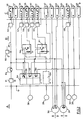
- the monitoring system itself is made up of three basic parts, namely a set of transducers, switches or the like, generally denoted by the reference A, a set of timers and counters generally denoted by the reference C, and circuitry including gating means, denoted by the reference B, interconnecting the components A with the counters and timers C.
- the transducers and switches of section A are suitably mounted on the truck to detect its various physical operations and produce signals in accordance therewith.
- the pressure transducer 28 as previously mentioned, is fitted at the inlet to the lift cylinder and produces an electric signal representative of the pressure in the cylinder and hence the load applied to the vehicle.
- a speed transducer 29, which may be a generator driven by the truck wheels, is suitably mounted to detect motion of the truck by generating a signal in response to motion of the truck.
- a microswitch 30, operated by movements of the control lever 31 ( Figure 1) for extending and retracting the fork arms, is provided to detect such movements.
- a microswitch 32 operated by movements of the control lever 33 ( Figure 1) for tilting the mast 12, is provided to detect such movements.
- a reed switch 34 operated by lifting of the fork lift 13 remains closed for the whole of the lift time.
- a microswitch 35 is preferably mounted so as to be operated by the fitting of such attachment.
- the timers and counters of Section C include a timer 36 for recording "presence time", that is to say, the duration of activation of the system; a counter 37 for counting and recording the number of applications of a load to the vehicle, as detected by the pressure transducer 28; a timer 38 for recording the time in which the truck is driven in an unloaded condition; a timer 39 for recording the time in which the truck is stationary in an unloaded condition; a timer 40 for recording the time in which the truck is driven in a loaded condition; and a timer 41 for recording the time in which the truck is stationary in a loaded condition.
- the section C also includes a counter 42 for recording the number of applications of loads in excess of a first predetermined value corresponding to a predetermined fraction of the specified maximum load; a counter 43 for recording the number of reach operations of the fork arms initiated by the control lever 31; a counter 44 for recording the number of retract operations of the fork arms initiated by the control lever 31; a counter 45 for recording the number of tilt operations of the mast 12 initiated by the control lever 33; a timer 46 for recording the total lift time in response to operation of the reed switch 34; a counter 47 for recording the number of "event” operations in response to the attachments of a special load handling appliance to the fork lift truck; and a counter 48 for recording the number of overloads, that is to say applications of a load to the truck in excess of the specified maximum load value.
- Section B of the monitoring device provides a supply circuit 49 to which the timer circuit of the timer 36 is coupled by a relay 50.
- the supply circuit 49 is conveniently energized from a battery on the fork lift truck, and includes voltage regulators 51,52 for maintaining a constant voltage.
- the supply circuit is activated by operation of an on-off switch 53, which an operator will turn on at the beginning of a working shift.
- the timer 36 is therefore responsive to operation of the switch 53 and so records the "presence time".
- timing circuits of timers 38, 39, 40 and 41 are interconnected with the pressure transducer 28 and the speed transducer 29 by way of gating circuitry which will now be described.
- the pressure transducer 28 in response to the application of a load to the fork lift truck, actuates a selective switching means 54 including a first two-state switch 55 shown as a single-pole, double-throw switch.
- the switch 55 is shown in its normal, no-load condition.
- the common terminal of the switch 55 is connected to the supply circuit.
- One output terminal of the switch 55 is connected to the counter 37 while the other output terminal is connected to the common terminal of a second two-state switch 56.
- the output terminals of the switch 56 are connected respectively to the timer circuits of timers 38,39 via relays 57,58.
- the two-state switch 55 is operated when a minimum load is applied to the truck.
- the switching means 54 also includes a first single-pole, single-throw switch 59 operable by the pressure transducer 28 in response to the application of a load exceeding a first predetermined value.
- a second single-pole, single-throw switch 60 is operable by the pressure transducer 28 in response to the application of a load exceeding a second predetermined value (specified maximum value) higher than the first.
- the switch 55 When a load is applied to the vehicle, the switch 55 is operated so as to disconnect the switch 56 from the supply circuit 49 and to connect the common terminal of a third two-state switch 61 to the supply circuit.
- the output terminals of the switch 61 are connected respectively with the timer circuit of timers 40,41 by way of relays 62,63.
- the switches 56 and 61 are solenoid-operated switches responsive to the speed transducer 29 in accordance with the detection of vehicle motion.
- an interface circuitry 64 between the speed transducer and the switches 56,61 will usually be required.
- the single-pole, double-throw switches 55, 56 and 61 thus constitute a first selective switching means operable in accordance with the presence of a vehicle load, and a second selective switching means operable by the detection of vehicle motion, the switches thus defining four different modes of usage of the fork lift truck, namely stationary/unloaded, stationary/loaded, driven/unloaded, and driven/loaded.
- the duration of each mode of usage is recorded by the respective one of the timers 38, 39, 40, 41 in accordance with the condition of the switches.
- the switch 59 operable by the pressure transducer 28, is interconnected with the counter 42 which responds to the switch operation by recording the number of load applications in excess of the first predetermined value.
- the switch 60 also operable by the pressure transducer 28, is interconnected with the counter 48 which responds to the switch operation by recording the number of load applications in excess of the specified maximum value.
- the microswitch 30 is interconnected with the supply circuit 49 by way of the switch 55 when the truck is loaded, and is operable in accordance with extension and retraction of fork arms to activate a counter 43 for recording the number of reach operations or a counter 44 for recording the number of retract operations.
- microswitch 32 is interconnected with the supply circuit 49 by way of the switch 55 when the truck is loaded, and with the counter 45.
- the counter 45 responds to operation of the microswitch 32, by recording the number of tilt operations performed on the mast 12.
- the reed switch 34 operated by lifting of the fork lift, is used to close a circuit for activating the timer 46, for recording the total lift time.
- the timer 46 is coupled to the circuit via a relay 65.
- the switching device 35 operable by the fitting of an optional load handling attachment, is used to actuate the counter 47 for recording the number of such fittings.
- Sections B and C of the monitoring system may conveniently be housed in a common housing to be mounted on the fork lift truck, the housing being provided with a connector socket carrying the electrical connections to the transducers and switches of Section A and to the truck power supply.
- the monitoring system when activated at the beginning of a working shift and deactivated at the end of the working shift, by operation of the on-off switch 53, records the pattern of truck usage during the shift.
- the timers and counters show: the "presence time”, i.e. duration of the shift; the "truck stationary and unloaded” time; the “truck driven and unloaded” time; the “truck stationary and loaded” time; the “truck driven and loaded” time; the number of load applications; the number of applications of a load exceeding a predetermined amount; the number of load applications exceeding a specified maximum load; the number of "reach” operations; the number of "retract” operations; the number of "tilt” operations; the number of "lift time”; the number of "event” activations.
- a printer facility will be coupled to the monitoring system.
- This facility will include a central processing unit coupled to the system via a buffer interface for processing the signals applied to the timers and counters, and a printer controlled by the central processing unit for printing the respective readings of said timers and counters.
Landscapes
- Engineering & Computer Science (AREA)
- Mechanical Engineering (AREA)
- Sustainable Development (AREA)
- Sustainable Energy (AREA)
- Power Engineering (AREA)
- Transportation (AREA)
- Life Sciences & Earth Sciences (AREA)
- Physics & Mathematics (AREA)
- General Physics & Mathematics (AREA)
- Forklifts And Lifting Vehicles (AREA)
- Electric Propulsion And Braking For Vehicles (AREA)
- Warehouses Or Storage Devices (AREA)
- Transmission Devices (AREA)
- Control Of Conveyors (AREA)
Priority Applications (1)
| Application Number | Priority Date | Filing Date | Title |
|---|---|---|---|
| AT88108150T ATE89941T1 (de) | 1987-06-01 | 1988-05-20 | Elektrisches ueberwachungssystem fuer lasten befoerdernde fahrzeuge. |
Applications Claiming Priority (2)
| Application Number | Priority Date | Filing Date | Title |
|---|---|---|---|
| US07/055,859 US4757712A (en) | 1987-06-01 | 1987-06-01 | Electric monitoring system for load handling vehicles |
| US55859 | 1998-04-06 |
Publications (3)
| Publication Number | Publication Date |
|---|---|
| EP0293697A2 true EP0293697A2 (de) | 1988-12-07 |
| EP0293697A3 EP0293697A3 (en) | 1989-06-28 |
| EP0293697B1 EP0293697B1 (de) | 1993-05-26 |
Family
ID=22000624
Family Applications (1)
| Application Number | Title | Priority Date | Filing Date |
|---|---|---|---|
| EP88108150A Expired - Lifetime EP0293697B1 (de) | 1987-06-01 | 1988-05-20 | Elektrisches Überwachungssystem für Lasten befördernde Fahrzeuge |
Country Status (7)
| Country | Link |
|---|---|
| US (1) | US4757712A (de) |
| EP (1) | EP0293697B1 (de) |
| JP (1) | JPS63305702A (de) |
| AT (1) | ATE89941T1 (de) |
| AU (1) | AU598376B2 (de) |
| CA (1) | CA1304479C (de) |
| DE (1) | DE3881280T2 (de) |
Cited By (2)
| Publication number | Priority date | Publication date | Assignee | Title |
|---|---|---|---|---|
| EP0351453B1 (de) * | 1988-07-18 | 1994-02-09 | Alert-O-Brake Systems Inc. | Überwachungssystem für Lasten bewegende Fahrzeuge |
| WO2001028805A1 (en) * | 1999-10-21 | 2001-04-26 | Tokyo R & D Co., Ltd | Electric vehicle and method for managing the same |
Families Citing this family (16)
| Publication number | Priority date | Publication date | Assignee | Title |
|---|---|---|---|---|
| JPH0610378A (ja) * | 1992-06-26 | 1994-01-18 | Komatsu Ltd | 掘削積込機の作業量検出装置 |
| JP2000109299A (ja) | 1998-10-02 | 2000-04-18 | Nippon Yusoki Co Ltd | カウンタバランス型フォ−クリフトの荷役装置 |
| US6216069B1 (en) * | 1999-03-10 | 2001-04-10 | Daimlerchrysler Corporation | Hidden acquisition module for acquiring data from a vehicle |
| US6263039B1 (en) | 2000-01-04 | 2001-07-17 | Scott A. Ducharme | Load counter for dump truck or the like |
| US20050125247A1 (en) * | 2003-05-13 | 2005-06-09 | Ding Steven A. | Industrial vehicle fleet management system |
| US6758649B1 (en) * | 2003-05-21 | 2004-07-06 | Frank P. Scordilis | Fork lift attachment |
| KR20150106973A (ko) * | 2006-12-13 | 2015-09-22 | 크라운 이큅먼트 코포레이션 | 차대 관리 시스템 |
| US11225404B2 (en) | 2006-12-13 | 2022-01-18 | Crown Equipment Corporation | Information system for industrial vehicles |
| US10600256B2 (en) * | 2006-12-13 | 2020-03-24 | Crown Equipment Corporation | Impact sensing usable with fleet management system |
| US9984341B2 (en) * | 2006-12-13 | 2018-05-29 | Crown Equipment Corporation | Information system for industrial vehicles including cyclical recurring vehicle information message |
| US10013815B2 (en) * | 2006-12-13 | 2018-07-03 | Crown Equipment Corporation | Information system for industrial vehicles |
| MX2012001851A (es) * | 2009-08-12 | 2012-03-07 | Crown Equip Corp | Sistema de informacion para vehiculos industriales. |
| MX2012002649A (es) | 2009-09-01 | 2012-03-21 | Crown Equip Corp | Sistema de informacion para vehiculos industriales incluyendo mensaje de informacion de vehiculo recurrente ciclico. |
| US8196464B2 (en) * | 2010-01-05 | 2012-06-12 | The Raymond Corporation | Apparatus and method for monitoring a hydraulic pump on a material handling vehicle |
| US8635792B2 (en) | 2010-12-14 | 2014-01-28 | Caterpillar Inc. | Cycle counter for wheeled tractor scraper |
| CN108162801A (zh) * | 2017-12-29 | 2018-06-15 | 常州市武起常乐电机有限公司 | 小型纯电动汽车用电机控制器的控制方法 |
Family Cites Families (12)
| Publication number | Priority date | Publication date | Assignee | Title |
|---|---|---|---|---|
| US1414910A (en) * | 1922-05-02 | Means por indicating stopping | ||
| US3792445A (en) * | 1972-12-01 | 1974-02-12 | Mark & Son Ltd | Vehicle data recording system |
| US4068773A (en) * | 1975-04-03 | 1978-01-17 | Allis-Chalmers Corporation | Lift vehicle with fail-safe overload protective system |
| ZA76973B (en) * | 1976-02-18 | 1977-09-28 | Transputer Ltd | An accessory for a vehicle |
| US4206829A (en) * | 1976-12-27 | 1980-06-10 | Towmotor Corporation | Control system for lift trucks or the like |
| US4411577A (en) * | 1980-03-07 | 1983-10-25 | Rapistan Division, Lear Siegler, Inc. | Vehicle sensor monitoring system |
| JPS5790106A (en) * | 1980-11-26 | 1982-06-04 | Nippon Denso Co Ltd | Driving indicator for automobile |
| GB2095862B (en) * | 1981-03-31 | 1984-10-24 | Toyoda Automatic Loom Works | Fork lift control system |
| JPS57175241A (en) * | 1981-04-22 | 1982-10-28 | Caterpillar Mitsubishi Ltd | Car diagnosing system |
| US4478521A (en) * | 1981-11-09 | 1984-10-23 | Perfection Electronic Products Corp. | Digital time meter |
| US4516116A (en) * | 1981-12-16 | 1985-05-07 | Safety Devices (Engineering) Limited | Apparatus for visually displaying the load-moment, axle-load, or payload of a vehicle |
| DE3515422A1 (de) * | 1985-04-29 | 1986-10-30 | Privates Institut für Physikalisch Technische Auftragsforschung GmbH, 6100 Darmstadt | Flurfoerderzeug mit einem zaehlgeraet |
-
1987
- 1987-06-01 US US07/055,859 patent/US4757712A/en not_active Expired - Fee Related
-
1988
- 1988-01-05 JP JP63000171A patent/JPS63305702A/ja active Pending
- 1988-05-20 EP EP88108150A patent/EP0293697B1/de not_active Expired - Lifetime
- 1988-05-20 AT AT88108150T patent/ATE89941T1/de not_active IP Right Cessation
- 1988-05-20 DE DE88108150T patent/DE3881280T2/de not_active Expired - Fee Related
- 1988-05-20 CA CA000567392A patent/CA1304479C/en not_active Expired - Lifetime
- 1988-05-31 AU AU16785/88A patent/AU598376B2/en not_active Ceased
Cited By (2)
| Publication number | Priority date | Publication date | Assignee | Title |
|---|---|---|---|---|
| EP0351453B1 (de) * | 1988-07-18 | 1994-02-09 | Alert-O-Brake Systems Inc. | Überwachungssystem für Lasten bewegende Fahrzeuge |
| WO2001028805A1 (en) * | 1999-10-21 | 2001-04-26 | Tokyo R & D Co., Ltd | Electric vehicle and method for managing the same |
Also Published As
| Publication number | Publication date |
|---|---|
| DE3881280T2 (de) | 1993-12-16 |
| EP0293697B1 (de) | 1993-05-26 |
| US4757712A (en) | 1988-07-19 |
| ATE89941T1 (de) | 1993-06-15 |
| JPS63305702A (ja) | 1988-12-13 |
| DE3881280D1 (de) | 1993-07-01 |
| CA1304479C (en) | 1992-06-30 |
| AU598376B2 (en) | 1990-06-21 |
| EP0293697A3 (en) | 1989-06-28 |
| AU1678588A (en) | 1988-12-01 |
Similar Documents
| Publication | Publication Date | Title |
|---|---|---|
| EP0293697B1 (de) | Elektrisches Überwachungssystem für Lasten befördernde Fahrzeuge | |
| US4949263A (en) | Load handling vehicle monitoring system | |
| US5143386A (en) | Automatic leveling system | |
| EP0786432B1 (de) | Gerät und Verfahren zum Steuern eines Scherenhebers | |
| US4505111A (en) | Hydraulic control system for industrial vehicle | |
| US5240379A (en) | Hydraulic power unit | |
| CA2060344C (en) | Control device for work machine | |
| WO2001081231A1 (en) | A spreader | |
| US5305680A (en) | Control device for hydraulic actuating cylinders of a loading tailgate of a vehicle | |
| US4655039A (en) | Lift system | |
| EP1426207A2 (de) | Radfahrzeug mit einem Drehturm | |
| EP0232073A3 (de) | Güterhandhabungsfahrzeuge | |
| EP0996583A1 (de) | Integrierte steuerung für elektrische hubwagen | |
| JPH06135698A (ja) | フォークリフトの荷役制御装置 | |
| JPH0636075Y2 (ja) | リフト装置 | |
| US20240367718A1 (en) | Four-wheel steering control system and control method therefor | |
| CA1087281A (en) | Lift truck overload protective circuit having override feature | |
| KR910008171B1 (ko) | 자동 유압 속도 제어 시스템 | |
| CN1022904C (zh) | 轮式装载机过载报警装置 | |
| SU1244079A1 (ru) | Указатель нагрузки и вылета стрелы крана | |
| JPS6115102Y2 (de) | ||
| JPH0743215Y2 (ja) | ホイールローダの過積載警報装置 | |
| CA2306734A1 (en) | Control system for powered cargo bed | |
| JPH0669880B2 (ja) | リーチ式フォークリフトの荷役制御装置 | |
| JPH0281108U (de) |
Legal Events
| Date | Code | Title | Description |
|---|---|---|---|
| PUAI | Public reference made under article 153(3) epc to a published international application that has entered the european phase |
Free format text: ORIGINAL CODE: 0009012 |
|
| AK | Designated contracting states |
Kind code of ref document: A2 Designated state(s): AT BE CH DE ES FR GB GR IT LI LU NL SE |
|
| PUAL | Search report despatched |
Free format text: ORIGINAL CODE: 0009013 |
|
| AK | Designated contracting states |
Kind code of ref document: A3 Designated state(s): AT BE CH DE ES FR GB GR IT LI LU NL SE |
|
| 17P | Request for examination filed |
Effective date: 19891218 |
|
| 17Q | First examination report despatched |
Effective date: 19911220 |
|
| GRAA | (expected) grant |
Free format text: ORIGINAL CODE: 0009210 |
|
| RAP1 | Party data changed (applicant data changed or rights of an application transferred) |
Owner name: ALERT-O-BRAKE SYSTEMS INC. |
|
| AK | Designated contracting states |
Kind code of ref document: B1 Designated state(s): AT BE CH DE ES FR GB GR IT LI LU NL SE |
|
| PG25 | Lapsed in a contracting state [announced via postgrant information from national office to epo] |
Ref country code: IT Free format text: LAPSE BECAUSE OF FAILURE TO SUBMIT A TRANSLATION OF THE DESCRIPTION OR TO PAY THE FEE WITHIN THE PRE;WARNING: LAPSES OF ITALIAN PATENTS WITH EFFECTIVE DATE BEFORE 2007 MAY HAVE OCCURRED AT ANY TIME BEFORE 2007. THE CORRECT EFFECTIVE DATE MAY BE DIFFERENT FROM THE ONE RECORDED.SCRIBED TIME-LIMIT Effective date: 19930526 Ref country code: ES Free format text: THE PATENT HAS BEEN ANNULLED BY A DECISION OF A NATIONAL AUTHORITY Effective date: 19930526 Ref country code: GR Free format text: LAPSE BECAUSE OF FAILURE TO SUBMIT A TRANSLATION OF THE DESCRIPTION OR TO PAY THE FEE WITHIN THE PRESCRIBED TIME-LIMIT Effective date: 19930526 Ref country code: SE Effective date: 19930526 Ref country code: NL Effective date: 19930526 Ref country code: LI Effective date: 19930526 Ref country code: CH Effective date: 19930526 Ref country code: AT Effective date: 19930526 Ref country code: BE Effective date: 19930526 |
|
| REF | Corresponds to: |
Ref document number: 89941 Country of ref document: AT Date of ref document: 19930615 Kind code of ref document: T |
|
| REF | Corresponds to: |
Ref document number: 3881280 Country of ref document: DE Date of ref document: 19930701 |
|
| REG | Reference to a national code |
Ref country code: CH Ref legal event code: PL |
|
| ET | Fr: translation filed | ||
| NLV1 | Nl: lapsed or annulled due to failure to fulfill the requirements of art. 29p and 29m of the patents act | ||
| PLBE | No opposition filed within time limit |
Free format text: ORIGINAL CODE: 0009261 |
|
| STAA | Information on the status of an ep patent application or granted ep patent |
Free format text: STATUS: NO OPPOSITION FILED WITHIN TIME LIMIT |
|
| PGFP | Annual fee paid to national office [announced via postgrant information from national office to epo] |
Ref country code: FR Payment date: 19940511 Year of fee payment: 7 Ref country code: GB Payment date: 19940511 Year of fee payment: 7 |
|
| PGFP | Annual fee paid to national office [announced via postgrant information from national office to epo] |
Ref country code: DE Payment date: 19940524 Year of fee payment: 7 |
|
| 26N | No opposition filed | ||
| PG25 | Lapsed in a contracting state [announced via postgrant information from national office to epo] |
Ref country code: LU Free format text: LAPSE BECAUSE OF NON-PAYMENT OF DUE FEES Effective date: 19940531 |
|
| PG25 | Lapsed in a contracting state [announced via postgrant information from national office to epo] |
Ref country code: GB Effective date: 19950520 |
|
| GBPC | Gb: european patent ceased through non-payment of renewal fee |
Effective date: 19950520 |
|
| PG25 | Lapsed in a contracting state [announced via postgrant information from national office to epo] |
Ref country code: DE Effective date: 19960201 |
|
| PG25 | Lapsed in a contracting state [announced via postgrant information from national office to epo] |
Ref country code: FR Effective date: 19960229 |
|
| REG | Reference to a national code |
Ref country code: FR Ref legal event code: ST |
|
| REG | Reference to a national code |
Ref country code: FR Ref legal event code: ST |