EP0293631A2 - Dispositif de fixation d'un premier élément de construction à masse relativement petite sur un deuxième élément de construction à masse relativement grande et application du dispositif - Google Patents
Dispositif de fixation d'un premier élément de construction à masse relativement petite sur un deuxième élément de construction à masse relativement grande et application du dispositif Download PDFInfo
- Publication number
- EP0293631A2 EP0293631A2 EP88107316A EP88107316A EP0293631A2 EP 0293631 A2 EP0293631 A2 EP 0293631A2 EP 88107316 A EP88107316 A EP 88107316A EP 88107316 A EP88107316 A EP 88107316A EP 0293631 A2 EP0293631 A2 EP 0293631A2
- Authority
- EP
- European Patent Office
- Prior art keywords
- spring element
- rubber spring
- rubber
- component
- threaded sleeve
- Prior art date
- Legal status (The legal status is an assumption and is not a legal conclusion. Google has not performed a legal analysis and makes no representation as to the accuracy of the status listed.)
- Granted
Links
Images
Classifications
-
- F—MECHANICAL ENGINEERING; LIGHTING; HEATING; WEAPONS; BLASTING
- F16—ENGINEERING ELEMENTS AND UNITS; GENERAL MEASURES FOR PRODUCING AND MAINTAINING EFFECTIVE FUNCTIONING OF MACHINES OR INSTALLATIONS; THERMAL INSULATION IN GENERAL
- F16F—SPRINGS; SHOCK-ABSORBERS; MEANS FOR DAMPING VIBRATION
- F16F1/00—Springs
- F16F1/36—Springs made of rubber or other material having high internal friction, e.g. thermoplastic elastomers
- F16F1/371—Springs made of rubber or other material having high internal friction, e.g. thermoplastic elastomers characterised by inserts or auxiliary extension or exterior elements, e.g. for rigidification
- F16F1/3713—Springs made of rubber or other material having high internal friction, e.g. thermoplastic elastomers characterised by inserts or auxiliary extension or exterior elements, e.g. for rigidification with external elements passively influencing spring stiffness, e.g. rings or hoops
-
- F—MECHANICAL ENGINEERING; LIGHTING; HEATING; WEAPONS; BLASTING
- F16—ENGINEERING ELEMENTS AND UNITS; GENERAL MEASURES FOR PRODUCING AND MAINTAINING EFFECTIVE FUNCTIONING OF MACHINES OR INSTALLATIONS; THERMAL INSULATION IN GENERAL
- F16F—SPRINGS; SHOCK-ABSORBERS; MEANS FOR DAMPING VIBRATION
- F16F1/00—Springs
- F16F1/36—Springs made of rubber or other material having high internal friction, e.g. thermoplastic elastomers
- F16F1/373—Springs made of rubber or other material having high internal friction, e.g. thermoplastic elastomers characterised by having a particular shape
- F16F1/3732—Springs made of rubber or other material having high internal friction, e.g. thermoplastic elastomers characterised by having a particular shape having an annular or the like shape, e.g. grommet-type resilient mountings
Definitions
- the object of the invention is to show a rubber buffer which can be used in a particularly expedient manner to accommodate parts which are to be mounted in a vibrating manner or to be installed as spacers between surfaces which can be moved against one another.
- the primary object of the invention is to provide a device suitable for this purpose.
- the invention shows a particularly useful application.
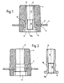
- a rubber buffer according to the invention is shown in a first embodiment as a central longitudinal section in FIG. 1, the two parts of the rubber buffer according to the invention according to FIG. 1 are shown as central longitudinal sections in FIG. 2, namely the rubber spring element and the threaded bushing.
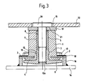
- 3 shows a further embodiment of the rubber buffer according to the invention in the installed state and thus the device according to the invention is again shown as a central longitudinal section.
- the rubber spring element 1 consists of an elastic material, in particular rubber, which is why rubber is used in connection with the invention when an elastic material is meant, that is to say, for example, an elastomer can replace the actual rubber.
- the rubber spring element is cylindrical and preferably tapered slightly tapering towards the upper end in the drawing. Near the other, lower in the drawing and consequently the end with the somewhat larger diameter, an annular groove is provided in the rubber spring element 1, the edges of which are slightly turned outward in a lip shape. An annular flange 2 is fixed in this annular groove, which is consequently superimposed by the upper annular groove lip 3 and is underlaid by the lower annular groove lip 4.
- the ring flange 2 consists of metal or a plastic with corresponding properties.
- a likewise essentially cylindrical longitudinal hole 5 is provided concentrically around the longitudinal axis of the rubber spring element 1. This longitudinal hole ends in the solution according to Fig.
- the extension is preferably a polygon, preferably a square.
- the diameter of the basic contour of the extension 6, in the case of a polygon, the diameter of the largest crisis corresponds at least approximately to the inside diameter of the first-mentioned ring flange 2, the outside diameter of which is significantly larger than the (largest) outside diameter of the rubber spring element 1.
- the ring groove for receiving the first-mentioned ring flange 2 lies between the inner surface of the extension 6 or the opening of the hole 5 into the extension 6 and a second ring groove 7. While the ring groove for the ring flange 2 has a rectangular cross-section around the ring flange without play and even with a predetermined bias, the second annular groove 7 has an arcuate cross section.
- a sleeve 8 is rotatably inserted, the upper portion 11 has a slightly larger inner diameter than the lower portion 12, which is provided with a screw thread 12a.
- the sleeve 8 has a radial flange 9 at the lower end to prevent rotation and to bear against the underside of the sleeve 8, whose outer contour and diameter corresponds to the outer contour and the diameter of the extension 6.
- the sleeve 8 is provided with an annular bead 10 with a spherical cross section, which is assigned to the flange 9 in the manner in which the annular groove 7 is associated with the extension 6 and whose cross section corresponds approximately to the cross section of the annular groove 7.
- the rubber spring element 1 is expanded to such an extent that the sleeve 8 can be inserted and is held in the rubber spring element 1 with a press fit after the expansion has ended (FIG. 1).
- the annular bead 10 lies in the annular groove 7, the radial flange 9 lies in the extension 6 in such a way that its inner end surface rests on the inner surface of the extension 6.
- the annular flange 2 and the radial flange 9 do not overlap in the radial direction, or at least to a small extent.
- the radial flange 9 has a significantly larger diameter than in the embodiment according to FIG.
- the rubber spring element 1 has no extension 6 of the longitudinal hole 5, and the radial flange 9 rests on the entire lower end face of the rubber spring element 1 and projects with a circular edge beyond the likewise circular end face of the rubber spring element 1.
- a plate-shaped first component 14 of relatively low mass is to be fixed in relation to any second component 13 of relatively large mass, for example the second component 13 is intended to be part of a vehicle bodywork which is to be made bullet-proof with an armor plate as a plate-shaped first component 14.
- An appropriate plurality of devices according to the invention are used for the determination, only one of which is shown and described in the installed state.
- the component 13 has a hole 15 and a ring 16 of a predetermined height is welded onto the component 14 on the side facing the component 13. Hole 13 and ring 16 are assigned to each other with the same axis.
- the device according to the invention with the flange 9 and the lower end of the rubber spring element 1 is inserted so far that the ring flange 2 on the upper edge of the ring 13 lie and is fixed in this position relative to the component 14 by ring flange 2 and ring 16, for example, permanently glued to one another or releasably connected to one another, for example by ring 16 at the upper end facing inwards and ring flange 2 having corresponding recesses, so that when inserted the cams can pass axially through the recesses and after rotation of the device according to the invention about its longitudinal axis the cams of the ring 16 lie over the non-recessed sections of the ring flange 2 and
- an annular disc 19 is placed on the top of the rubber spring element 1, but this may also have been previously placed on the rubber spring element and connected to it, for example glued.
- the outer diameter of the disk 19 is significantly larger than the diameter of the hole 15 of the component 13, while the inner diameter of the annular disk 18 corresponds approximately to the diameter of the section 11 of the longitudinal hole 5 of the sleeve 8.
- the screw 20 is inserted into the longitudinal hole 5 and screwed into its threaded section 12 until the head of the screw 20 is in the hole 15 has largely disappeared, with the interposition of a spring washer 21 resting on the annular disk 19 and by determining the distance between the radial flange 9 and the annular flange 2 or the first component 14 relative to the second component 13, the position of the lighter component 14 relative to the heavier component 13 is determined is and determines the bias in the rubber spring element 1.
- the outer diameter of the rubber spring element 1 in the area between the ring flange 2 and the end face of the spring element 1 or radial flange 9 closer to it is larger than the outer diameter of the rubber spring element 1 in the area between the ring flange 2 and the other end face of the rubber spring element 1.
- the component 14 is adjustable relative to the component 13 from a defined position. Since there is no metallic connection to each other, the two parts are vibration and temperature insulated from each other. Energy that strikes the component 14 vertically is absorbed in the rubber spring element 1 up to a relatively high value and is not passed on to the component 14.
- the component 14 can be fixed on the component 13 after appropriate preparation of the component 14 solely from the outside A of the component 13, the component 14 does not have to be interrupted in the area of the fastening be so that the connection is particularly suitable for releasably assigning an armor plate 14 to a vehicle structure 13.
- the device can absorb shear forces without the risk of damaging it. In the event of a fire, the rubber spring element 1 may burn, but the attachment of the component 14 to the component 13 would also be retained in principle.
Landscapes
- Engineering & Computer Science (AREA)
- General Engineering & Computer Science (AREA)
- Mechanical Engineering (AREA)
- Springs (AREA)
- Vibration Prevention Devices (AREA)
Applications Claiming Priority (2)
| Application Number | Priority Date | Filing Date | Title |
|---|---|---|---|
| DE8707802U DE8707802U1 (fr) | 1987-06-01 | 1987-06-01 | |
| DE8707802U | 1987-06-01 |
Publications (3)
| Publication Number | Publication Date |
|---|---|
| EP0293631A2 true EP0293631A2 (fr) | 1988-12-07 |
| EP0293631A3 EP0293631A3 (en) | 1990-05-02 |
| EP0293631B1 EP0293631B1 (fr) | 1993-11-10 |
Family
ID=6808709
Family Applications (1)
| Application Number | Title | Priority Date | Filing Date |
|---|---|---|---|
| EP88107316A Expired - Lifetime EP0293631B1 (fr) | 1987-06-01 | 1988-05-06 | Dispositif de fixation d'un premier élément de construction à masse relativement petite sur un deuxième élément de construction à masse relativement grande et application du dispositif |
Country Status (2)
| Country | Link |
|---|---|
| EP (1) | EP0293631B1 (fr) |
| DE (2) | DE8707802U1 (fr) |
Cited By (2)
| Publication number | Priority date | Publication date | Assignee | Title |
|---|---|---|---|---|
| EP0874175A2 (fr) * | 1997-04-25 | 1998-10-28 | Alps Electric Co., Ltd. | Dispositif résistant aux vibrations et dispositif d'entraínement de disque l'utilisant |
| WO2002006696A1 (fr) * | 2000-07-14 | 2002-01-24 | Basf Aktiengesellschaft | Element elastique |
Citations (8)
| Publication number | Priority date | Publication date | Assignee | Title |
|---|---|---|---|---|
| GB482260A (en) * | 1936-03-05 | 1938-03-21 | Hugh Compton Lord | Cushion joints or mountings |
| FR951846A (fr) * | 1946-08-28 | 1949-11-04 | Ford | Montage élastique |
| US2830780A (en) * | 1953-06-30 | 1958-04-15 | Schloss Fred | Low frequency noise and shock isolation mount |
| FR1260978A (fr) * | 1960-06-18 | 1961-05-12 | Goodrich Co B F | Support élastique |
| US3809427A (en) * | 1972-10-03 | 1974-05-07 | Bennett Equipment Corp | Vehicle body mount |
| DE2310560A1 (de) * | 1973-03-02 | 1974-09-05 | Continental Gummi Werke Ag | Membranfoermiges federelement |
| US3881767A (en) * | 1973-09-12 | 1975-05-06 | Gen Motors Corp | Vehicle impact energy absorption and suspension system |
| JPS5586936A (en) * | 1979-11-14 | 1980-07-01 | Showa Electric Wire & Cable Co Ltd | Manufacturing method of multistage anti-vibration rubber |
-
1987
- 1987-06-01 DE DE8707802U patent/DE8707802U1/de not_active Expired
-
1988
- 1988-05-06 DE DE88107316T patent/DE3885510D1/de not_active Expired - Fee Related
- 1988-05-06 EP EP88107316A patent/EP0293631B1/fr not_active Expired - Lifetime
Patent Citations (8)
| Publication number | Priority date | Publication date | Assignee | Title |
|---|---|---|---|---|
| GB482260A (en) * | 1936-03-05 | 1938-03-21 | Hugh Compton Lord | Cushion joints or mountings |
| FR951846A (fr) * | 1946-08-28 | 1949-11-04 | Ford | Montage élastique |
| US2830780A (en) * | 1953-06-30 | 1958-04-15 | Schloss Fred | Low frequency noise and shock isolation mount |
| FR1260978A (fr) * | 1960-06-18 | 1961-05-12 | Goodrich Co B F | Support élastique |
| US3809427A (en) * | 1972-10-03 | 1974-05-07 | Bennett Equipment Corp | Vehicle body mount |
| DE2310560A1 (de) * | 1973-03-02 | 1974-09-05 | Continental Gummi Werke Ag | Membranfoermiges federelement |
| US3881767A (en) * | 1973-09-12 | 1975-05-06 | Gen Motors Corp | Vehicle impact energy absorption and suspension system |
| JPS5586936A (en) * | 1979-11-14 | 1980-07-01 | Showa Electric Wire & Cable Co Ltd | Manufacturing method of multistage anti-vibration rubber |
Non-Patent Citations (1)
| Title |
|---|
| PATENT ABSTRACTS OF JAPAN, Band 4, Nr. 128 (M-31)[610], 9. September 1980; & JP-A-55 86 936 (SHOWA DENSEN DENRAN K.K.) 01-07-1980 * |
Cited By (5)
| Publication number | Priority date | Publication date | Assignee | Title |
|---|---|---|---|---|
| EP0874175A2 (fr) * | 1997-04-25 | 1998-10-28 | Alps Electric Co., Ltd. | Dispositif résistant aux vibrations et dispositif d'entraínement de disque l'utilisant |
| EP0874175A3 (fr) * | 1997-04-25 | 2000-04-12 | Alps Electric Co., Ltd. | Dispositif résistant aux vibrations et dispositif d'entraínement de disque l'utilisant |
| CN1111864C (zh) * | 1997-04-25 | 2003-06-18 | 阿尔卑斯电气株式会社 | 防振机构及采用该防振机构的盘驱动装置 |
| WO2002006696A1 (fr) * | 2000-07-14 | 2002-01-24 | Basf Aktiengesellschaft | Element elastique |
| US6857626B2 (en) | 2000-07-14 | 2005-02-22 | Basf Aktiengesellschaft | Spring element |
Also Published As
| Publication number | Publication date |
|---|---|
| EP0293631B1 (fr) | 1993-11-10 |
| EP0293631A3 (en) | 1990-05-02 |
| DE3885510D1 (de) | 1993-12-16 |
| DE8707802U1 (fr) | 1987-07-23 |
Similar Documents
| Publication | Publication Date | Title |
|---|---|---|
| DE2718170C3 (de) | Befestigungsclip für verkleidete Abdeckplatten, insbesondere für Kraftfahrzeuge | |
| EP0937311B1 (fr) | Dispositif de fixation d'un capteur de distance sur un vehicule automobile | |
| DE4406270C1 (de) | Federnde Scheibe zum Sichern von Schrauben, Muttern oder dergleichen | |
| EP1104852A1 (fr) | Dispositif de fixation detachable de deux pieces antivibratoire avec une goupille, un ressort de retenue et un anneau antivibratoire | |
| EP1086289A1 (fr) | Dispositif de fixation d'une plaque de verre sur un support place du cote d'un batiment | |
| DE2054998A1 (de) | Karosserie Rahmenverbindungselement fur Kraftfahrzeuge | |
| DE2818790C2 (de) | Zerlegbarer Tisch | |
| DE3132855A1 (de) | Rosetten-unterteil | |
| EP3153725B1 (fr) | Procede et dispositif de fixation d'un composant en plastique sur un composant porteur | |
| DE3739663A1 (de) | Einstellbares federbein fuer kraftfahrzeuge | |
| DE3822322C2 (de) | Pralldämpfer mit einer Sollbruchstelle | |
| DE3207922C1 (de) | Schwenklagerung für ein Türhalteband eines Türfeststellers für Kraftfahrzeugtüren | |
| DE3138534C2 (fr) | ||
| DE2109812C3 (de) | Halter zum elastischen Befestigen von Vorsatzplatten an Wänden oder Fußböden in Räumen | |
| EP0293631B1 (fr) | Dispositif de fixation d'un premier élément de construction à masse relativement petite sur un deuxième élément de construction à masse relativement grande et application du dispositif | |
| EP0047961B1 (fr) | Accouplement de rotule d'attelage pour véhicules moteur | |
| DE3811401C2 (fr) | ||
| DE1683207B1 (de) | Befestigungsvorrichtung fuer im Abstand veraenderliche Bauwerksverkleidungen | |
| DE69720665T2 (de) | Aufhängungsvorrichtung für ein Kraftfahrzeug | |
| DE19647607C2 (de) | Vorrichtung zur Festlegung von zweischaligen Isolierglasscheiben an Tragkonstruktionen | |
| DE4136598A1 (de) | Gummi-metall-federelement | |
| EP1096156B1 (fr) | Système de fixation à vis pré-montée | |
| DE3910644C2 (fr) | ||
| DE2946993C2 (fr) | ||
| DE4321708A1 (de) | Heizkörperkonsole |
Legal Events
| Date | Code | Title | Description |
|---|---|---|---|
| PUAI | Public reference made under article 153(3) epc to a published international application that has entered the european phase |
Free format text: ORIGINAL CODE: 0009012 |
|
| AK | Designated contracting states |
Kind code of ref document: A2 Designated state(s): CH DE FR GB LI |
|
| RIN1 | Information on inventor provided before grant (corrected) | ||
| PUAL | Search report despatched |
Free format text: ORIGINAL CODE: 0009013 |
|
| AK | Designated contracting states |
Kind code of ref document: A3 Designated state(s): CH DE FR GB LI |
|
| 17P | Request for examination filed |
Effective date: 19901025 |
|
| 17Q | First examination report despatched |
Effective date: 19920428 |
|
| GRAA | (expected) grant |
Free format text: ORIGINAL CODE: 0009210 |
|
| AK | Designated contracting states |
Kind code of ref document: B1 Designated state(s): CH DE FR GB LI |
|
| ET | Fr: translation filed | ||
| GBT | Gb: translation of ep patent filed (gb section 77(6)(a)/1977) |
Effective date: 19931111 |
|
| REF | Corresponds to: |
Ref document number: 3885510 Country of ref document: DE Date of ref document: 19931216 |
|
| PLBE | No opposition filed within time limit |
Free format text: ORIGINAL CODE: 0009261 |
|
| STAA | Information on the status of an ep patent application or granted ep patent |
Free format text: STATUS: NO OPPOSITION FILED WITHIN TIME LIMIT |
|
| 26N | No opposition filed | ||
| PGFP | Annual fee paid to national office [announced via postgrant information from national office to epo] |
Ref country code: GB Payment date: 20000508 Year of fee payment: 13 |
|
| PGFP | Annual fee paid to national office [announced via postgrant information from national office to epo] |
Ref country code: CH Payment date: 20000510 Year of fee payment: 13 |
|
| PGFP | Annual fee paid to national office [announced via postgrant information from national office to epo] |
Ref country code: FR Payment date: 20000530 Year of fee payment: 13 |
|
| PG25 | Lapsed in a contracting state [announced via postgrant information from national office to epo] |
Ref country code: GB Free format text: LAPSE BECAUSE OF NON-PAYMENT OF DUE FEES Effective date: 20010506 |
|
| PG25 | Lapsed in a contracting state [announced via postgrant information from national office to epo] |
Ref country code: LI Free format text: LAPSE BECAUSE OF NON-PAYMENT OF DUE FEES Effective date: 20010605 Ref country code: CH Free format text: LAPSE BECAUSE OF NON-PAYMENT OF DUE FEES Effective date: 20010605 |
|
| PGFP | Annual fee paid to national office [announced via postgrant information from national office to epo] |
Ref country code: DE Payment date: 20010608 Year of fee payment: 14 |
|
| GBPC | Gb: european patent ceased through non-payment of renewal fee |
Effective date: 20010506 |
|
| REG | Reference to a national code |
Ref country code: CH Ref legal event code: PL |
|
| PG25 | Lapsed in a contracting state [announced via postgrant information from national office to epo] |
Ref country code: FR Free format text: LAPSE BECAUSE OF NON-PAYMENT OF DUE FEES Effective date: 20020131 |
|
| PG25 | Lapsed in a contracting state [announced via postgrant information from national office to epo] |
Ref country code: DE Free format text: LAPSE BECAUSE OF NON-PAYMENT OF DUE FEES Effective date: 20021203 |