EP0293387B1 - Method of forming hard facings on materials - Google Patents
Method of forming hard facings on materials Download PDFInfo
- Publication number
- EP0293387B1 EP0293387B1 EP87901529A EP87901529A EP0293387B1 EP 0293387 B1 EP0293387 B1 EP 0293387B1 EP 87901529 A EP87901529 A EP 87901529A EP 87901529 A EP87901529 A EP 87901529A EP 0293387 B1 EP0293387 B1 EP 0293387B1
- Authority
- EP
- European Patent Office
- Prior art keywords
- substrate
- hard material
- relatively
- edge
- relatively hard
- Prior art date
- Legal status (The legal status is an assumption and is not a legal conclusion. Google has not performed a legal analysis and makes no representation as to the accuracy of the status listed.)
- Expired
Links
- 239000000463 material Substances 0.000 title claims abstract description 38
- 238000005552 hardfacing Methods 0.000 title claims abstract description 16
- 238000000034 method Methods 0.000 title claims description 30
- 239000000758 substrate Substances 0.000 claims abstract description 52
- 229910001315 Tool steel Inorganic materials 0.000 claims abstract description 9
- 238000002844 melting Methods 0.000 claims abstract description 5
- 230000008018 melting Effects 0.000 claims abstract description 5
- 239000011159 matrix material Substances 0.000 claims description 12
- 229910052751 metal Inorganic materials 0.000 claims description 11
- 239000002184 metal Substances 0.000 claims description 11
- 150000001247 metal acetylides Chemical class 0.000 claims description 11
- 230000008569 process Effects 0.000 claims description 11
- PXHVJJICTQNCMI-UHFFFAOYSA-N Nickel Chemical compound [Ni] PXHVJJICTQNCMI-UHFFFAOYSA-N 0.000 claims description 6
- 229910001220 stainless steel Inorganic materials 0.000 claims description 6
- 239000010935 stainless steel Substances 0.000 claims description 6
- 238000000227 grinding Methods 0.000 claims description 5
- 229910000734 martensite Inorganic materials 0.000 claims description 5
- 239000011651 chromium Substances 0.000 claims description 4
- 239000010941 cobalt Substances 0.000 claims description 4
- 229910017052 cobalt Inorganic materials 0.000 claims description 4
- GUTLYIVDDKVIGB-UHFFFAOYSA-N cobalt atom Chemical compound [Co] GUTLYIVDDKVIGB-UHFFFAOYSA-N 0.000 claims description 4
- 238000005520 cutting process Methods 0.000 claims description 4
- 239000002023 wood Substances 0.000 claims description 4
- VYZAMTAEIAYCRO-UHFFFAOYSA-N Chromium Chemical compound [Cr] VYZAMTAEIAYCRO-UHFFFAOYSA-N 0.000 claims description 3
- 229910052804 chromium Inorganic materials 0.000 claims description 3
- 229910052759 nickel Inorganic materials 0.000 claims description 3
- 239000004033 plastic Substances 0.000 claims description 3
- 229920003023 plastic Polymers 0.000 claims description 3
- 229910001339 C alloy Inorganic materials 0.000 claims description 2
- 229910001080 W alloy Inorganic materials 0.000 claims description 2
- QVYYOKWPCQYKEY-UHFFFAOYSA-N [Fe].[Co] Chemical compound [Fe].[Co] QVYYOKWPCQYKEY-UHFFFAOYSA-N 0.000 claims description 2
- 239000010937 tungsten Substances 0.000 claims description 2
- WFKWXMTUELFFGS-UHFFFAOYSA-N tungsten Chemical compound [W] WFKWXMTUELFFGS-UHFFFAOYSA-N 0.000 claims description 2
- 238000003825 pressing Methods 0.000 claims 4
- 230000001131 transforming effect Effects 0.000 claims 1
- 238000000576 coating method Methods 0.000 abstract description 45
- 239000011248 coating agent Substances 0.000 abstract description 39
- 229910001347 Stellite Inorganic materials 0.000 abstract description 13
- AHICWQREWHDHHF-UHFFFAOYSA-N chromium;cobalt;iron;manganese;methane;molybdenum;nickel;silicon;tungsten Chemical compound C.[Si].[Cr].[Mn].[Fe].[Co].[Ni].[Mo].[W] AHICWQREWHDHHF-UHFFFAOYSA-N 0.000 abstract description 13
- 230000008021 deposition Effects 0.000 abstract 1
- 229910001209 Low-carbon steel Inorganic materials 0.000 description 12
- 235000019589 hardness Nutrition 0.000 description 11
- 229910045601 alloy Inorganic materials 0.000 description 7
- 239000000956 alloy Substances 0.000 description 7
- XEEYBQQBJWHFJM-UHFFFAOYSA-N Iron Chemical compound [Fe] XEEYBQQBJWHFJM-UHFFFAOYSA-N 0.000 description 4
- 230000015572 biosynthetic process Effects 0.000 description 4
- 229910000831 Steel Inorganic materials 0.000 description 3
- 229910000725 T1 high speed steel Inorganic materials 0.000 description 3
- 238000010438 heat treatment Methods 0.000 description 3
- 239000011122 softwood Substances 0.000 description 3
- 239000010959 steel Substances 0.000 description 3
- 238000003466 welding Methods 0.000 description 3
- IJGRMHOSHXDMSA-UHFFFAOYSA-N Atomic nitrogen Chemical compound N#N IJGRMHOSHXDMSA-UHFFFAOYSA-N 0.000 description 2
- 229910000997 High-speed steel Inorganic materials 0.000 description 2
- 229910001566 austenite Inorganic materials 0.000 description 2
- 230000008901 benefit Effects 0.000 description 2
- 238000005219 brazing Methods 0.000 description 2
- 229910052742 iron Inorganic materials 0.000 description 2
- 238000004519 manufacturing process Methods 0.000 description 2
- 238000001000 micrograph Methods 0.000 description 2
- 239000002245 particle Substances 0.000 description 2
- 230000002093 peripheral effect Effects 0.000 description 2
- 239000007787 solid Substances 0.000 description 2
- 238000005496 tempering Methods 0.000 description 2
- 238000011282 treatment Methods 0.000 description 2
- 238000009827 uniform distribution Methods 0.000 description 2
- 229910000531 Co alloy Inorganic materials 0.000 description 1
- 230000008859 change Effects 0.000 description 1
- 238000001816 cooling Methods 0.000 description 1
- 230000007547 defect Effects 0.000 description 1
- 239000012895 dilution Substances 0.000 description 1
- 238000010790 dilution Methods 0.000 description 1
- 238000009826 distribution Methods 0.000 description 1
- 238000000635 electron micrograph Methods 0.000 description 1
- QFXZANXYUCUTQH-UHFFFAOYSA-N ethynol Chemical group OC#C QFXZANXYUCUTQH-UHFFFAOYSA-N 0.000 description 1
- 230000004927 fusion Effects 0.000 description 1
- 230000020169 heat generation Effects 0.000 description 1
- 238000003384 imaging method Methods 0.000 description 1
- 230000000977 initiatory effect Effects 0.000 description 1
- 238000005304 joining Methods 0.000 description 1
- 239000007788 liquid Substances 0.000 description 1
- 230000014759 maintenance of location Effects 0.000 description 1
- 150000002739 metals Chemical class 0.000 description 1
- 238000002156 mixing Methods 0.000 description 1
- 230000004048 modification Effects 0.000 description 1
- 238000012986 modification Methods 0.000 description 1
- 229910052757 nitrogen Inorganic materials 0.000 description 1
- 238000001878 scanning electron micrograph Methods 0.000 description 1
- 239000006104 solid solution Substances 0.000 description 1
- 230000009466 transformation Effects 0.000 description 1
- 239000011800 void material Substances 0.000 description 1
Images

Classifications
-
- B—PERFORMING OPERATIONS; TRANSPORTING
- B23—MACHINE TOOLS; METAL-WORKING NOT OTHERWISE PROVIDED FOR
- B23K—SOLDERING OR UNSOLDERING; WELDING; CLADDING OR PLATING BY SOLDERING OR WELDING; CUTTING BY APPLYING HEAT LOCALLY, e.g. FLAME CUTTING; WORKING BY LASER BEAM
- B23K35/00—Rods, electrodes, materials, or media, for use in soldering, welding, or cutting
- B23K35/22—Rods, electrodes, materials, or media, for use in soldering, welding, or cutting characterised by the composition or nature of the material
- B23K35/24—Selection of soldering or welding materials proper
- B23K35/32—Selection of soldering or welding materials proper with the principal constituent melting at more than 1550 degrees C
- B23K35/327—Selection of soldering or welding materials proper with the principal constituent melting at more than 1550 degrees C comprising refractory compounds, e.g. carbides
-
- B—PERFORMING OPERATIONS; TRANSPORTING
- B23—MACHINE TOOLS; METAL-WORKING NOT OTHERWISE PROVIDED FOR
- B23K—SOLDERING OR UNSOLDERING; WELDING; CLADDING OR PLATING BY SOLDERING OR WELDING; CUTTING BY APPLYING HEAT LOCALLY, e.g. FLAME CUTTING; WORKING BY LASER BEAM
- B23K20/00—Non-electric welding by applying impact or other pressure, with or without the application of heat, e.g. cladding or plating
- B23K20/12—Non-electric welding by applying impact or other pressure, with or without the application of heat, e.g. cladding or plating the heat being generated by friction; Friction welding
- B23K20/1215—Non-electric welding by applying impact or other pressure, with or without the application of heat, e.g. cladding or plating the heat being generated by friction; Friction welding for other purposes than joining, e.g. built-up welding
-
- Y—GENERAL TAGGING OF NEW TECHNOLOGICAL DEVELOPMENTS; GENERAL TAGGING OF CROSS-SECTIONAL TECHNOLOGIES SPANNING OVER SEVERAL SECTIONS OF THE IPC; TECHNICAL SUBJECTS COVERED BY FORMER USPC CROSS-REFERENCE ART COLLECTIONS [XRACs] AND DIGESTS
- Y10—TECHNICAL SUBJECTS COVERED BY FORMER USPC
- Y10S—TECHNICAL SUBJECTS COVERED BY FORMER USPC CROSS-REFERENCE ART COLLECTIONS [XRACs] AND DIGESTS
- Y10S148/00—Metal treatment
- Y10S148/902—Metal treatment having portions of differing metallurgical properties or characteristics
- Y10S148/905—Cutting tool
Definitions
- This invention relates to the formation of hard facings along edges on materials by friction surfacing.
- British Patent Specification No.572789 (Hans Klopstock) describes a method for joining or welding metals in which a rotating rod or bar of weld metal is fed into contact with the metal part or parts to be treated with such continuity of pressure and is moved relatively thereto at such speed that the frictional heat generated causes the end of the rod or bar and the metal to attain welding temperature. The result is that the metal of the rod or bar becomes deposited on the metal under treatment to form a local enlargement or joins two juxtaposed metal parts together or fills in blow-holes or the like.
- edge tools such as blades, knives and guillotines have been made by three routes, one involving carburising and heat-treating the surface of the tool, the second involving brazing or roll-bonding to the tool an insert of high speed tool steel, and a third using solid high speed steel or other typical cutting alloys.
- GB-A- 1 018 412 discloses a method for applying a hard facing along an edge of an agricultural blade by friction surfacing hard material onto a substrate.
- This invention provides a method of this kind, characterised in that the substrate edge is formed with a recess of angular profile with its back face inclined at an angle of 35 to 55 o to its other face and is joined to the other face by a radiused region and the relatively hard material is deposited in the recess in intimate contact with the back face and the radiused region and fills the recess.
- the relatively hard material provides metal carbides in a matrix based on a metal selected from the group consisting of iron cobalt and nickel.
- the process of the invention which operates at high rates of strain and at high temperatures below the melting points of the relatively hard material and the substrate gives rise to very finely divided carbides uniformly distributed in a matrix of very fine microstructure, resulting in unexpectedly good mechanical properties and service life, even when deposited on a mild steel or stainless steel substrate.
- the method provides for effective use of the relatively hard material because mixing at the interface with the substrate occures to a minimal extent, and a very good union at the interface is achieved.
- the coating may be applied to substrates of thickness as low as 3mm without damage or unacceptable distortion, depending upon the particular hard material and substrate, suitable substrate materials being mild steel and stainless steel.
- the articles that may be made by the method of this invention include cutting blades which have shown unexpectedly long service lives and ease of re-grinding, skates, valves and valve seats. Further, a wear resistant face can be formed on the flight edges of exturder screws (used extensively in food and plastics industries both as an original equipment process and as a reclamation process).
- the invention provides also uses of such articles for planing wood or as an industrial guillotine blade.
- the invention may be employed for forming edge tool surfaces on hand tools such as screw drivers and chisels that may benefit from hard facing.
- the formation of surface coatings on substrates by friction coating is known.
- the material from which the coating is formed on existing machines using a round-section bar or rod is between 3 and 25 mm diameter depending upon the application and it is believed that this can be increased to over 40 mm required with an appropriately powerful machine.
- the bar is rotated at a typical peripheral speed of from 1-2 metres per second under pressure, to form a hot plasticised layer in the bar where it interfaces with the substrate.
- By moving the substrate which may be a plate or rod across the face of the rotating bar, termed a "mechtrode"
- This invention is based on the discovery that hard facings of carbide-containing, iron-based, cobalt-based or less commonly nickel-based alloys can usefully be deposited along a milled edge channel of a workpiece.
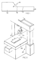
- a mild steel workpiece 10 is cut to length, and a recess 12 is formed along an edge 13 thereof.
- the recess 12 is generally of angular profile with its back face inclined at an angle typically from 35 degrees to 55 degrees to the cut face, preferably about 45 degrees and joined to the cut face 14 by a radiused region 15.
- the angle of the back face of the workpiece takes the natural geometry of the hot plasticised mechtrode material as it progresses along the recess, and the radiused region 15 maintains intimate contact for heat generation continuously across the profile of the groove avoiding development in the finished workpiece of a linear region of poorly bonded coating.
- the depth and width of the channel 12 will depend on the nature of the workpiece 10 and of the type of blade which it is intended to provide.
- the blade 10 is clamped by clamping means (not shown) firmly onto a bed 20 of a coating machine 22 having a mechtrode 24 firmly fixed in a rotary chuck 26.
- Figure 2 shows the general machine format with the blade 10 in place for coating.
- the coating machine will normally be provided with sensors providing inputs to a feedback control loop so that a defined mechtrode pressure in N/mm2, a defined rate of rotation and a defined rate of feed of the mechtrode 24 relative to the workpiece 10 is maintained.
- the initial or “touchdown" phase of the coating process in which friction heating of the mechtrode 24 up to its equilibrium condition takes place is important, as is the phase in which the mechtrode 24 is lifted from contact with the blade 10 at the end of the run.
- the touchdown phase will occupy five seconds and the coating phase will occupy 200 seconds, the spindle speed being about 1250 rpm and the workpiece 10 feed rate 4 mm per second the force on the mechtrode 24 being about 12 kN.
- the result is to produce a coating about 0.7 mm thick or more and of length typically 800 mm.
- the thickness of the layer produced depends on the material of the mechtrode 24, the diameter of the mechtrode and to a lesser extent the material and thickness of the substrate 10.
- a 10 mm mechtrode may typically produce a coating in the range 0.2 to 1 mm thick whereas a 25 mm diameter mechtrode may produce a coating in the range 0.5 to 2 mm thick. Any desired thickness may be built up by means of repeated coating.
- the width of the layer produced will be similar to the diameter of the mechtrode employed. Mechtrodes of diameter up to 50 mm can be employed, wider coatings if required being produced by parallel tracks, eg. in the production of large industrial guillotine blades for the paper and plastics industries.
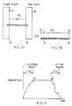
- the blade 10 has lines A and B defining completion of touchdown and initiation of liftoff respectively.
- the touchdown period occupies five seconds and the liftoff period is less than 1 second.
- a coating having consistent properties is produced.
- touchdown and liftoff occur on a start plate 7 and an end plate 8, substantially the whole of the workpiece 10 having an effective coating.
- touchdown and liftoff occur at the ends 9 of the workpiece which are subsequently removed.
- a heat treatment step is required in the case of high speed tool steels in order to temper the coating back from its as deposited high hardness.
- tempering is carried out for two periods of one hour at a temperature of 560 o C when secondary hardening occurs.
- the blade 10 After completion of the coating formation and heat treatment steps the blade 10 is ground along its edge to clean and sharpen the coating. Because the present process does not involve melting, the degree of distortion of the workpiece 10 is much less than in conventional brazing or welding processes.
- a significant feature of the process is that it copes with the two different types of hardfacing alloys.
- allotropic transformation takes place to relatively soft austenite at high temperatures which is quenched to hard martensite as a result of the process.
- Stellite type alloys undergo no allotropic change and simply experience high temperature softening to enable coating to take place.
- a feature of the friction coating process is that the coating parameters are selected to generate the intended heat flow characteristics. Parameters are optimised to generate sufficient heat to enable the friction interface to rise from a position in contact with the substrate 10 to a position along the mechtrode 24 spaced a small distance from the substrate 10.
- a significant metallurgical advantage is that the alloy is hot worked during coating so that the fine structure resulting has attendant good properties.
- the resulting microstructure is a very fine array of angular complex carbide particles in a matrix of, in the case of a high speed transformable tool steel, very fine martensite which on subsequent tempering is enhanced by secondary hardening.
- the size of the carbides in the matrix is such that there are relatively few carbides of size above two microns with a very uniform distribution of the carbides through the matrix, the fineness of the microstructure giving the observed better edge retention properties.
- Normally high speed tool steels have a much coarser microstructure with large carbide particles in a banded form and a coarse martensitic matrix.
- the austenite which is present at the equilibrium condition of the mechtrode during coating is hot worked at very high strain rates, it has a very fine microstructure which on the immediately following rapid cooling transforms to an equally fine martensitic structure.
- the resulting microstructure is uniform with a very uniform array of angular complex carbides in a solid solution matrix of cobalt/chromium.
- a mild steel blade for a knife of a wood planing machine was coated with a 12 mm edge coating of T1 high speed tool steel (18:4:1 type).
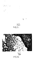
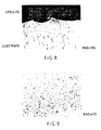
- the coated blade was sectioned, ground, polished and examined in a scanning electron microscope fitted with a back-scatter detector that gives atomic number contrast to the micrographs dark contrast from low atomic number (2) and light areas from high Z regions.
- Figure 5 which is a scanning electron micrograph there may be seen an upper plain region of mild steel connected by a well-defined interface to a high speed tool steel layer which has finely divided uniformly distributed carbides.
- Figure 6 is an enlarged interface area of Figure 5 in back-scatter imaging mode, showing that any interface void (black area) is about one micron in size, such voids being of infrequent occurrence.
- the homogeneity of matrix is also evident from its uniform appearance.
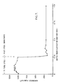
- the hardness of the T1 coating normal to the tool surface and a scan across the interface on the polished section were carried out using a Vickers bench microhardness tester.
- the hardness of the coating and mild steel substrate, measured at 1000 gms, were 860 ⁇ 30 and 173 ⁇ 9 respectively.
- the scan of hardness, measured at 50 gms load, across the interface is plotted in Figure 7.
- a solid T1 blade has a life of typically 4,000 metres of softwood.
- Blades were manufactured as in Example 1 except that immediately after coating, the blade was immersed in liquid nitrogen for 24 hours followed by two one-hour treatments at 560 o C.
- the resulting blades when fitted to the same machine as in Example 1 were in useable condition after 50,000 metres of softwood had been planed, after which the blades were removed.
- a blade according to Example 1 was re-sharpened by grinding to remove 0.4 mm of material.
- a conventional T1 blade typically loses 1-2 mm during re-grinding.
- the Vickers hardness of Stellite 6 as cast was 410 whereas the deposited coating had a surface Vickers hardness using a 30 Kg load of 665 and a section hardness of 640, the increase in hardness being attributable to the fine carbide distribution and the very fine matrix structure.
- a skater's blade 30 (Figures 10, 11) of mild steel is formed along both lower sides with recesses in which BT1 high speed tool steel is deposited to form hard facings 32 as described in Figure 1, followed by grinding and finishing.
- a poppet valve 34 for an engine exhaust is formed with a peripheral recess 36 into which is deposited a layer 38 of Stellite 6. It is envisaged that other hard facing alloys such as those in the Tristelle range (iron based alloys available from Stoody Deloro Stellite) may be used in place of Stellite 6.
Landscapes
- Engineering & Computer Science (AREA)
- Mechanical Engineering (AREA)
- Other Surface Treatments For Metallic Materials (AREA)
- Pressure Welding/Diffusion-Bonding (AREA)
- Coating By Spraying Or Casting (AREA)
Priority Applications (1)
| Application Number | Priority Date | Filing Date | Title |
|---|---|---|---|
| AT87901529T ATE79318T1 (de) | 1986-02-17 | 1987-02-13 | Verfahren zum auftragen von hartmetall auf materialien. |
Applications Claiming Priority (2)
| Application Number | Priority Date | Filing Date | Title |
|---|---|---|---|
| GB868603832A GB8603832D0 (en) | 1986-02-17 | 1986-02-17 | Forming hard edges on materials |
| GB8603832 | 1986-02-17 |
Publications (2)
| Publication Number | Publication Date |
|---|---|
| EP0293387A1 EP0293387A1 (en) | 1988-12-07 |
| EP0293387B1 true EP0293387B1 (en) | 1992-08-12 |
Family
ID=10593176
Family Applications (1)
| Application Number | Title | Priority Date | Filing Date |
|---|---|---|---|
| EP87901529A Expired EP0293387B1 (en) | 1986-02-17 | 1987-02-13 | Method of forming hard facings on materials |
Country Status (7)
| Country | Link |
|---|---|
| US (1) | US4930675A (enExample) |
| EP (1) | EP0293387B1 (enExample) |
| JP (1) | JPH01502097A (enExample) |
| CA (1) | CA1263573A (enExample) |
| DE (1) | DE3781145T2 (enExample) |
| GB (2) | GB8603832D0 (enExample) |
| WO (1) | WO1987004957A1 (enExample) |
Families Citing this family (41)
| Publication number | Priority date | Publication date | Assignee | Title |
|---|---|---|---|---|
| DE3873772T2 (de) * | 1987-04-15 | 1993-03-18 | Frictec Ltd | Verfahren zum auftragsschweissen von materialien. |
| GB8808479D0 (en) * | 1988-04-11 | 1988-05-11 | Welding Inst | Bimetal faceplates |
| GB2222378B (en) * | 1988-08-30 | 1992-01-08 | Friction Technology Ltd | Forming hard facings on materials |
| GB2242848A (en) * | 1990-04-12 | 1991-10-16 | Frictec Ltd | Depositing coating on materials |
| EP0460901A3 (en) * | 1990-06-06 | 1993-09-29 | The Welding Institute | Surfacing a convex substrate |
| CA2043739A1 (en) * | 1990-06-06 | 1991-12-07 | Wayne Morris Thomas | Forming composite materials |
| GB9025696D0 (en) * | 1990-11-27 | 1991-01-09 | Welding Inst | Friction surfacing with in-process forging/forming |
| MY109553A (en) * | 1991-01-10 | 1997-02-28 | Bhp Steel Jla Pty Ltd | Continuously coating a moving metal strip |
| US5183390A (en) * | 1991-07-10 | 1993-02-02 | Westinghouse Electric Corp. | Method of forming a trailing edge on a steam turbine blade and the blade made thereby |
| GB2268430B (en) * | 1992-07-07 | 1996-02-07 | Frictec Ltd | Method of coating materials |
| GB9325135D0 (en) * | 1993-12-08 | 1994-02-09 | Rolls Royce Plc | Manufacture of wear resistant components |
| NO941144D0 (no) * | 1994-03-28 | 1994-03-28 | Norsk Hydro As | Fremgangsmåte ved friksjonssveising og anordning for samme |
| US5653299A (en) * | 1995-11-17 | 1997-08-05 | Camco International Inc. | Hardmetal facing for rolling cutter drill bit |
| JPH10141019A (ja) * | 1996-11-15 | 1998-05-26 | Fuji Oozx Inc | 内燃機関用タペット及びその製造方法 |
| EP1153156B1 (de) | 1999-01-22 | 2002-09-11 | Elpatronic Ag | Verfahren zum abdecken von verletzten schutzschichtstellen, vorrichtung zur durchführung des verfahrens und ein transportsystem |
| ES2211528T3 (es) * | 1999-03-24 | 2004-07-16 | Framatome Anp Gmbh | Procedimiento y dispositivo para la soldadura de dos piezas. |
| US6457629B1 (en) | 1999-10-04 | 2002-10-01 | Solidica, Inc. | Object consolidation employing friction joining |
| US6398883B1 (en) * | 2000-06-07 | 2002-06-04 | The Boeing Company | Friction stir grain refinement of structural members |
| US7560067B2 (en) * | 2001-07-16 | 2009-07-14 | Sherman Andrew J | Powder friction forming |
| US6948784B2 (en) | 2002-03-06 | 2005-09-27 | Deere & Company | Track pin bushing having a metallurgically bonded coating |
| US9138805B2 (en) | 2002-03-06 | 2015-09-22 | Deere & Company | Method for applying wear resistant coating to mechanical face seal |
| US9616951B2 (en) * | 2002-03-06 | 2017-04-11 | Deere & Company | Non-carburized components of track-type machines having a metallurgically bonded coating |
| US8684475B2 (en) * | 2002-03-06 | 2014-04-01 | Deere & Company | Components of track-type machines having a metallurgically bonded coating |
| US7163754B2 (en) * | 2003-10-23 | 2007-01-16 | Deere & Company | Sprocket wheel having a metallurgically bonded coating and method for producing same |
| US20080041921A1 (en) | 2005-09-26 | 2008-02-21 | Kevin Creehan | Friction stir fabrication |
| US9266191B2 (en) | 2013-12-18 | 2016-02-23 | Aeroprobe Corporation | Fabrication of monolithic stiffening ribs on metallic sheets |
| US8875976B2 (en) | 2005-09-26 | 2014-11-04 | Aeroprobe Corporation | System for continuous feeding of filler material for friction stir welding, processing and fabrication |
| US8632850B2 (en) | 2005-09-26 | 2014-01-21 | Schultz-Creehan Holdings, Inc. | Friction fabrication tools |
| US9511445B2 (en) | 2014-12-17 | 2016-12-06 | Aeroprobe Corporation | Solid state joining using additive friction stir processing |
| US9511446B2 (en) | 2014-12-17 | 2016-12-06 | Aeroprobe Corporation | In-situ interlocking of metals using additive friction stir processing |
| US20110113950A1 (en) * | 2006-01-10 | 2011-05-19 | Reed Charles K | Composite material having a layer including entrained particles and method of making same |
| RU2350443C2 (ru) * | 2006-07-10 | 2009-03-27 | Вячеслав Владимирович Алексеев | Способ сварки трением алюминиевых сплавов |
| US9003681B2 (en) * | 2006-09-18 | 2015-04-14 | Deere & Company | Bucket teeth having a metallurgically bonded coating and methods of making bucket teeth |
| DE102008044763A1 (de) * | 2008-08-28 | 2010-03-04 | Hochschule Für Angewandte Wissenschaften - Fachhochschule Kempten | Beschichtungsverfahren |
| JP5289990B2 (ja) * | 2009-01-28 | 2013-09-11 | 日立建機株式会社 | 丸軸表面の改質方法及びこれに用いる改質装置 |
| DE102010054453A1 (de) * | 2010-12-14 | 2012-06-14 | Hochschule Für Angewandte Wissenschaften - Fachhochschule Kempten | Verfahren zum Fügen von Werkstücken |
| CN104185531B (zh) | 2011-12-16 | 2017-09-19 | 肯普滕应用技术大学-高等专科学校 | 通过摩擦挤压焊接连结两个基本金属片状工件的方法 |
| CN103805929B (zh) * | 2013-12-16 | 2016-06-08 | 湖北工业大学 | 一种工件涂层的表面处理方法和装置 |
| CN111655403B (zh) | 2017-10-31 | 2022-10-14 | 梅尔德制造公司 | 固态增材制造系统和材料的组成与结构 |
| JP6960329B2 (ja) * | 2017-12-26 | 2021-11-05 | 日立Geニュークリア・エナジー株式会社 | 耐食耐摩耗盛金の形成方法および耐食耐摩耗弁の製造方法 |
| US12291784B2 (en) * | 2022-10-07 | 2025-05-06 | Goodrich Corporation | Corrosion protection using metallic coating |
Family Cites Families (7)
| Publication number | Priority date | Publication date | Assignee | Title |
|---|---|---|---|---|
| GB1018412A (en) * | 1963-05-31 | 1966-01-26 | Valentin Dmitrievich Voznesens | Welding |
| GB1102601A (en) * | 1964-04-07 | 1968-02-07 | Hopkinsons Ltd | Improvements relating to formation of non-corrodible and/or resistant seating surfaces on metal valve components |
| US3537172A (en) * | 1967-08-21 | 1970-11-03 | Valentin Dmitrievich Voznesens | Method of friction welding |
| DE2219406A1 (de) * | 1971-04-22 | 1972-11-09 | The British Oxygen Co. Ltd., London | Metallhärtungsverfahren und nach diesem Verfahren hergestelltes Hartmetall |
| AU516925B2 (en) * | 1977-03-08 | 1981-07-02 | The Commonwealth Industrial Gases Limited | Subzero heat (cold) treatment of tool tips |
| DE3219260A1 (de) * | 1982-05-21 | 1983-11-24 | Lawton GmbH & Co KG, 7200 Tuttlingen | Verfahren zum einbringen eines harten materials in den ausgesparten beanspruchungsbereich des grundkoerpers eines chirurgischen instruments und chirurgisches instrument |
| US4625401A (en) * | 1984-06-25 | 1986-12-02 | Amp Incorporated | Method of gold coating an article |
-
1986
- 1986-02-17 GB GB868603832A patent/GB8603832D0/en active Pending
-
1987
- 1987-02-13 WO PCT/GB1987/000107 patent/WO1987004957A1/en not_active Ceased
- 1987-02-13 EP EP87901529A patent/EP0293387B1/en not_active Expired
- 1987-02-13 JP JP62501302A patent/JPH01502097A/ja active Granted
- 1987-02-13 DE DE8787901529T patent/DE3781145T2/de not_active Expired - Fee Related
- 1987-02-16 CA CA000529813A patent/CA1263573A/en not_active Expired
-
1988
- 1988-02-13 GB GB8817851A patent/GB2210572B/en not_active Expired
-
1989
- 1989-09-26 US US07/412,418 patent/US4930675A/en not_active Expired - Lifetime
Also Published As
| Publication number | Publication date |
|---|---|
| GB2210572B (en) | 1990-10-17 |
| DE3781145D1 (de) | 1992-09-17 |
| DE3781145T2 (de) | 1993-01-21 |
| JPH0478415B2 (enExample) | 1992-12-11 |
| GB2210572A (en) | 1989-06-14 |
| GB8817851D0 (en) | 1988-09-28 |
| US4930675A (en) | 1990-06-05 |
| WO1987004957A1 (en) | 1987-08-27 |
| GB8603832D0 (en) | 1986-03-26 |
| CA1263573A (en) | 1989-12-05 |
| EP0293387A1 (en) | 1988-12-07 |
| JPH01502097A (ja) | 1989-07-27 |
Similar Documents
| Publication | Publication Date | Title |
|---|---|---|
| EP0293387B1 (en) | Method of forming hard facings on materials | |
| US8096221B2 (en) | Method of producing a cutting blade and cutting blade thus produced | |
| US4117302A (en) | Method for fusibly bonding a coating material to a metal article | |
| US4725512A (en) | Materials transformable from the nonamorphous to the amorphous state under frictional loadings | |
| US9393984B2 (en) | Utility knife blade | |
| US4755237A (en) | Methods for making cutting tools | |
| Vedani | Microstructural evolution of tool steels after Nd-YAG laser repair welding | |
| US20030127086A1 (en) | Method and apparatus for cutting granite | |
| Wilks | Performance of diamonds as cutting tools for precision machining | |
| Zhang et al. | Investigations of the hybrid laser polishing and high-temperature tribological properties of the 316L stainless steel formed by selective laser melting | |
| GB2222378A (en) | Forming hard facings on materials | |
| EP0377562B1 (en) | Method of surfacing materials | |
| Sharipov et al. | Interactive methods for increasing wear resistance of cutting tool blades | |
| Keen | Some observations on the wear of diamond tools used in piston machining | |
| Stephenson et al. | Surface finishing of Ni–Cr–B–Si composite coatings by precision grinding | |
| Ambroza et al. | Formation of build up layers microstructure by arc automatic overlay welding using secondary raw material powders | |
| GB2242848A (en) | Depositing coating on materials | |
| Liyanage | Microstructure and properties of Ni-alloy and Ni-WC composite overlays | |
| Yen-Hung et al. | Wear behaviour and microstructure of laser-processed low carbon steel with chromium | |
| EP1872896B1 (en) | A method for producing a sharp-edged tool | |
| KR100569896B1 (ko) | 내마모습동부품의 제조방법_ | |
| RU1815057C (ru) | Способ восстановлени режущих элементов рабочих органов машин | |
| Parisianto et al. | Effect of laser power and steel and nickel-based alloy substrates on hardness and wear resistance of laser-deposited stellite coatings | |
| van Kalken | Friction Surfacing | |
| Abbas et al. | Wear studies of laser produced alloy and composite deposits |
Legal Events
| Date | Code | Title | Description |
|---|---|---|---|
| PUAI | Public reference made under article 153(3) epc to a published international application that has entered the european phase |
Free format text: ORIGINAL CODE: 0009012 |
|
| 17P | Request for examination filed |
Effective date: 19880729 |
|
| AK | Designated contracting states |
Kind code of ref document: A1 Designated state(s): AT BE CH DE FR GB IT LI LU NL SE |
|
| RAP1 | Party data changed (applicant data changed or rights of an application transferred) |
Owner name: FRICTECH LIMITED |
|
| RAP1 | Party data changed (applicant data changed or rights of an application transferred) |
Owner name: FRICTEC LIMITED |
|
| 17Q | First examination report despatched |
Effective date: 19900418 |
|
| GRAA | (expected) grant |
Free format text: ORIGINAL CODE: 0009210 |
|
| AK | Designated contracting states |
Kind code of ref document: B1 Designated state(s): AT BE CH DE FR GB IT LI LU NL SE |
|
| PG25 | Lapsed in a contracting state [announced via postgrant information from national office to epo] |
Ref country code: IT Free format text: LAPSE BECAUSE OF FAILURE TO SUBMIT A TRANSLATION OF THE DESCRIPTION OR TO PAY THE FEE WITHIN THE PRE;WARNING: LAPSES OF ITALIAN PATENTS WITH EFFECTIVE DATE BEFORE 2007 MAY HAVE OCCURRED AT ANY TIME BEFORE 2007. THE CORRECT EFFECTIVE DATE MAY BE DIFFERENT FROM THE ONE RECORDED.SCRIBED TIME-LIMIT Effective date: 19920812 Ref country code: NL Effective date: 19920812 Ref country code: CH Effective date: 19920812 Ref country code: BE Effective date: 19920812 Ref country code: LI Effective date: 19920812 Ref country code: AT Effective date: 19920812 |
|
| REF | Corresponds to: |
Ref document number: 79318 Country of ref document: AT Date of ref document: 19920815 Kind code of ref document: T |
|
| REF | Corresponds to: |
Ref document number: 3781145 Country of ref document: DE Date of ref document: 19920917 |
|
| ET | Fr: translation filed | ||
| REG | Reference to a national code |
Ref country code: CH Ref legal event code: PL |
|
| NLV1 | Nl: lapsed or annulled due to failure to fulfill the requirements of art. 29p and 29m of the patents act | ||
| PG25 | Lapsed in a contracting state [announced via postgrant information from national office to epo] |
Ref country code: LU Free format text: LAPSE BECAUSE OF NON-PAYMENT OF DUE FEES Effective date: 19930228 |
|
| PLBE | No opposition filed within time limit |
Free format text: ORIGINAL CODE: 0009261 |
|
| STAA | Information on the status of an ep patent application or granted ep patent |
Free format text: STATUS: NO OPPOSITION FILED WITHIN TIME LIMIT |
|
| 26N | No opposition filed | ||
| EAL | Se: european patent in force in sweden |
Ref document number: 87901529.5 |
|
| REG | Reference to a national code |
Ref country code: GB Ref legal event code: IF02 |
|
| PGFP | Annual fee paid to national office [announced via postgrant information from national office to epo] |
Ref country code: GB Payment date: 20040203 Year of fee payment: 18 |
|
| PGFP | Annual fee paid to national office [announced via postgrant information from national office to epo] |
Ref country code: FR Payment date: 20040220 Year of fee payment: 18 |
|
| PGFP | Annual fee paid to national office [announced via postgrant information from national office to epo] |
Ref country code: SE Payment date: 20040225 Year of fee payment: 18 |
|
| PGFP | Annual fee paid to national office [announced via postgrant information from national office to epo] |
Ref country code: DE Payment date: 20040310 Year of fee payment: 18 |
|
| PG25 | Lapsed in a contracting state [announced via postgrant information from national office to epo] |
Ref country code: GB Free format text: LAPSE BECAUSE OF NON-PAYMENT OF DUE FEES Effective date: 20050213 |
|
| PG25 | Lapsed in a contracting state [announced via postgrant information from national office to epo] |
Ref country code: SE Free format text: LAPSE BECAUSE OF NON-PAYMENT OF DUE FEES Effective date: 20050214 |
|
| PG25 | Lapsed in a contracting state [announced via postgrant information from national office to epo] |
Ref country code: DE Free format text: LAPSE BECAUSE OF NON-PAYMENT OF DUE FEES Effective date: 20050901 |
|
| EUG | Se: european patent has lapsed | ||
| GBPC | Gb: european patent ceased through non-payment of renewal fee |
Effective date: 20050212 |
|
| PG25 | Lapsed in a contracting state [announced via postgrant information from national office to epo] |
Ref country code: FR Free format text: LAPSE BECAUSE OF NON-PAYMENT OF DUE FEES Effective date: 20051031 |
|
| REG | Reference to a national code |
Ref country code: FR Ref legal event code: ST Effective date: 20051031 |