EP0293173B1 - Rotoranordnung eines Drehflügelflugzeuges - Google Patents
Rotoranordnung eines Drehflügelflugzeuges Download PDFInfo
- Publication number
- EP0293173B1 EP0293173B1 EP88304704A EP88304704A EP0293173B1 EP 0293173 B1 EP0293173 B1 EP 0293173B1 EP 88304704 A EP88304704 A EP 88304704A EP 88304704 A EP88304704 A EP 88304704A EP 0293173 B1 EP0293173 B1 EP 0293173B1
- Authority
- EP
- European Patent Office
- Prior art keywords
- rotor
- blade
- rotorcraft
- rotors
- shafts
- Prior art date
- Legal status (The legal status is an assumption and is not a legal conclusion. Google has not performed a legal analysis and makes no representation as to the accuracy of the status listed.)
- Expired
Links
- 230000033001 locomotion Effects 0.000 claims description 10
- 230000007246 mechanism Effects 0.000 claims description 8
- 230000005540 biological transmission Effects 0.000 claims description 3
- 238000000034 method Methods 0.000 description 5
- 125000004122 cyclic group Chemical group 0.000 description 2
- 238000013016 damping Methods 0.000 description 2
- 230000000694 effects Effects 0.000 description 2
- 238000011065 in-situ storage Methods 0.000 description 2
- 238000013459 approach Methods 0.000 description 1
- 238000006243 chemical reaction Methods 0.000 description 1
- 238000002485 combustion reaction Methods 0.000 description 1
- 150000001875 compounds Chemical class 0.000 description 1
- 230000008878 coupling Effects 0.000 description 1
- 238000010168 coupling process Methods 0.000 description 1
- 238000005859 coupling reaction Methods 0.000 description 1
- 230000005484 gravity Effects 0.000 description 1
- 230000002093 peripheral effect Effects 0.000 description 1
Images



Classifications
-
- B—PERFORMING OPERATIONS; TRANSPORTING
- B64—AIRCRAFT; AVIATION; COSMONAUTICS
- B64C—AEROPLANES; HELICOPTERS
- B64C27/00—Rotorcraft; Rotors peculiar thereto
- B64C27/04—Helicopters
- B64C27/08—Helicopters with two or more rotors
Definitions
- This invention relates to a rotor arrangement for a rotorcraft and in particular to an arrangement which comprises a plurality of intermeshing rotors having single lift surface blades.
- the invention has broad application to various types of rotorcraft, including conventionally powered free flying helicopters, although it has been developed primarily for use in a craft which is intended to hover at the end of a tether.
- the craft may be held aloft by the reaction between the rotors and high velocity winds or by motor drive applied to the rotors.
- Motor drive may be derived from an internal combustion engine or from one or more electric motors and, in the case of a tethered craft, energy may be supplied to the engine or motor by way of the tether.
- the motor may be operated in a generating mode and be used to harness wind energy acting on the rotors.
- the craft whether free flying or tethered, may be used simply to carry a sensor, such as a remotely controlled camera, or other device and, thus, the craft may be constructed in a size and manner appropriate to an unmanned craft.
- multi-rotor craft including one which incorporates two intermeshing, two-bladed counter-rotating rotors with a 90° phase difference between the rotors.
- craft have been developed which use rotors having blades which have a single lifting surface, including one craft which uses two spaced-apart such rotors with separate drive units for each of the rotors.
- US-A-3,053,480 discloses a helicopter drone which has four intermeshing two-bladed rotors which are driven such that one diagonally disposed pair of the rotors co-rotate in a first direction whilst the other diagonally disposed pair of rotors co-rotate in the opposite direction.
- the present invention is directed to one which employs four intermeshing rotors, with each rotor having a single blade, or, alternatively expressed, having a blade with a single lifting surface. Also, the rotors are mounted to respective rotor shafts which are divergently inclined with respect to one another in the direction of the rotors. This arrangement provides a compact drive to all rotors from a single power source or from a number of coupled power sources.
- the present invention may be defined broadly as providing a rotor craft comprising four intermeshing rotors coupled to common drive unit, each rotor being connected to an associated rotor shaft by way of a mechanism which provides for torque transmission and which permits rotor flapping and pitch adjustment.
- One pair of diagonally positioned rotors is arranged to be driven so as to co-rotate in one direction and the other pair of diagonally positioned rotors is arranged to be driven so as to co-rotate in the opposite direction, and means are provided for adjusting the pitch angle of each rotor.
- the rotorcraft is characterized in that the rotors are coupled to the driven unit by respective said rotor shafts, in that each rotor comprises a single rotatable blade having a lifting surface and an oppositely projecting substantially non-lifting balance arm, and in that the rotor shafts are inclined with respect to one another in a manner such that the rotor shafts diverge in the direction of the rotors whereby the path surface traced by each blade during rotation is inclined with respect to each other path surface.
- the four-rotor arrangement of the present invention facilitates the employment of a relatively simple control system for the rotors, and the arrangement obviates the need for cyclic pitch control and complex mechanical systems which normally are required to effect cyclic pitch control. It is envisaged that collective pitch control only will be applied to the rotors, with differential such control being applied to various ones of the rotors in order to effect manoeuvring of the craft.
- the rotorcraft comprises a body portion 20 which is mounted upon pods or skids 21.
- the body portion houses a drive motor and associated equipment, to be referred to in more detail below, and it is intended to house a camera (not shown) for use in aerial photography or reconnaissance.
- the craft incorporates four intermeshing rotors 22 to 25 which are rotatable about inclined axes 22A to 25A respectively.
- the two rotors 22 and 24 lie parallel to one another and the other two rotors 23 and 25 lie parallel to one another.
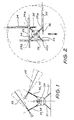
- the rotors 22, 24 and 23, 25 that have diagonally positioned axes of rotation are disposed parallel to ech other, and at four instants in time during each revolution the adjacent rotors will be disposed at rightangles to one another, as shown in Figure 2.
- the dotted outline in Figure 2 indicates the total area which is swept by the four rotors, and the dotted outline shown in Figure 1 indicates the maximum flapping angle through which each rotor blade travels.
- each rotor 22 to 25 are coupled to a common drive unit 26 which is shown in Figure 9, and each rotor comprises a single rotating blade 27 having an oppositely projecting (integrally formed) radial balance arm 28.
- the blade 27 is shaped with a single lifting surface to provide aerodynamic lift.
- the radial balance arm 28 does not have a lifting surface and it serves solely to carry a balance weight 29 which functions to balance centrifugal forces which exist in rotation of the rotor.
- the balance arm 28 preferably has a length in the order of 20% to 35% of the length of the blade 27 and it is expected that the length of the balance arm will never exceed 40% of the length of the blade.
- Each of the rotors 22, 25 extends through and is clamped in a univeral joint 30, which will be described below with reference to Figures 5 and 6, and the rotor is formed with an aperture 31 which is centred on the axis of rotation of the rotor.
- the aperture 31 is intended to provide clearance around a pitch control shaft 32 which projects through the aperture.
- the rotors 22 to 25 are coupled to the drive unit 26 by respective drive shafts (i.e., rotor shafts) 33 to 36 and the shafts are inclined with respect to one another such that the path surface traced by each of the blades 27 is inclined with respect to each other path surface.
- Each of the shafts 33 to 36 is formed along at least a portion of its length as a tube so that it may accommodate the pitch control shaft 32, which extends longitudinally within the rotor shaft.
- the universal joint 30 is fixed to the upper end of each of the rotor shafts 33 to 36 and, as shown in Figures 5 and 6, the universal joint has a yoke 38 which provides a trunnion mounting for a blade carrier 39.
- the blade carrier pivots about the yoke axis 40 and, thus, permits see-sawing pivotal (flapping) movement of the blade 27 and its oppositely projecting radial arm 28.
- the blade 27 and radial arm 28 are connected to the blade carrier 39 by clamp members 41 and 42, and such clamp members are pivotably connected to the blade carrier 39 by way of a pivot pin 43.
- This pivotal mounting allows the rotor blade 27 and the oppositely extending radial arm 28 to pivot about the longitudinal axis 44 of the rotor blade and, therefore, to adjust the pitch angle of the blade.
- the clamp members 41 and 42 have laterally projecting lever arms 45 and the lever arms are connected to a terminal end 46 of the pitch control shaft 32 by a connecting elements 47. Rectilinear movement of the shaft 32 translates to pivotal movement of the lever arm 45 and, thus, upward and downward movement of the shaft 32 causes angular adjustment of the blade pitch.
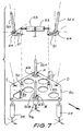
- two of the blade pitch control shafts 32A and 32B are positively but rotatably connected by way of bearings 63 to a tilting plate 50 at points indicated by letters "A" and "B".
- the remaining two pitch control shafts 32C and 32D are rotatably connected to bell-crank levers 51 by way of bearings 64, and they meet (but are not directly connected to) the tilting plate at points "C", and "D".
- the bell-crank levers 51 are pivotably connected to the tilting plate 50 by way of mounting arms 52, and the bell-crank levers 51 are connected to actuators 53. By operating the actuators 53, the pitch control shafts 32C and 32D are caused to move upwardly and downwardly with respect to the tilting plate 50.
- the tilting plate 50 is itself supported by three further actuators 54, 55 and 56 which are located at the apices of a triangle.
- One of the rams 56 connects with a central point in the plate and the other two actuators 54 and 55 connect with the plate at peripheral points.
- Uniform (simultaneous) actuation of all three of the actuators 54, 55 and 56 will result in collective pitch being applied to (or taken from) all four rotor blades.
- differential collective pitch may be applied to the rotors by actuating any one or two of the three actuators 54 to 56.
- roll control of the craft may be exerted by the actuator 55, and pitch control of the craft may be exerted by actuator 54.
- Yaw control may be exercised by the actuators 53 and, of course, simultaneous actuation of a number of the actuators 53 through to 56 will result in compound movement of the craft.
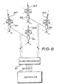
- the pitch control shafts 32 may be actuated by coupling each of the shafts to an associated actuator 60, as shown in Figure 8. Operation of the actuators 60 is in this case controlled by a microprocessor 61 to which inputs are provided from a controller 62.
- the controller 62 may derive its inputs from pilot actuated levers and/or pedals or from a remote transmitter.
- the rotorcraft in accordance with the invention permits enhanced stability and controllability relative to the more conventional forms of rotorcraft.
Landscapes
- Engineering & Computer Science (AREA)
- Mechanical Engineering (AREA)
- Aviation & Aerospace Engineering (AREA)
- Toys (AREA)
- Nozzles For Electric Vacuum Cleaners (AREA)
Claims (9)
- Drehflügel-Flugzeug mit vier ineinandergreifend umlaufenden mit einer gemeinsamen Antriebseinheit (26) gekoppelten Rotoren (22-25), wobei jeder Rotor (22-25) mit einer zugehörigen Rotorwelle (33-36) über einen Mechanismus verbunden ist, der für Drehmomentübertragung sorgt und Einstellung des Schlagens und des Anstellwinkels für den Rotor zuläßt, wobei ein Paar diagonal angeordnete Rotoren (22 und 24) antriebsmäßig so ausgelegt ist, daß sie in einer Richtung miteinander rotieren, und daß andere Paar diagonal angeordnete Rotoren (23 und 25) antriebsmäßig so ausgelegt ist, daß sie in der entgegengesetzten Richtung miteinander rotieren, und Mittel (32) vorgesehen sind zum Einstellen des Anstellwinkels jedes Rotors; dadurch gekennzeichnet, daß die Rotoren (22-25) mit der angetriebenen Einheit durch jeweilige Rotorwellen (33-36) gekoppelt sind, daß jeder Rotor (22-25) ein einziges drehbares Blatt (27) mit einer Auftriebsfläche und einen in entgegengesetzter Richtung abstehenden im wesentlichen nicht zum Auftrieb beitragenden Ausgleichsarm (28) besitzt, und daß die Rotorwellen (33-36) gegeneinander in einer solchen Weise geneigt sind, daß die Rotorwellen in Richtung der Rotoren (22-25) divergieren, wodurch die durch jedes Blatt (27) während der Drehung beschriebene Wegfläche gegen jede andere derartige Wegfläche geneigt ist.
- Drehflügel-Flugzeug nach Anspruch 1, weiter dadurch gekennzeichnet, daß die Rotorwellen (33-36) geometrisch an den Ecken eines Quadrats zentriert sind.
- Drehflügel-Flugzeug nach Anspruch 1 oder 2, weiter dadurch gekennzeichnet, daß die Rotorwellen (33-36) symmetrisch zu beiden Seiten der Mittellinie vorne/hinten des Drehflügel-Flugzeugs angeordnet sind.
- Drehflügel-Flugzeug nach einem der Ansprüche 1 bis 3, weiter dadurch gekennzeichnet, daß die Rotoren (22-24 und 23-25), die jeweils diagonal angeordnete Drehachsen besitzen, in Draufsicht gesehen parallel zueinander angeordnet sind.
- Drehflügel-Flugzeug nach einem der vorangehenden Ansprüche, weiter dadurch gekennzeichnet, daß der Ausgleichsarm (28) jedes Rotors (22-25) eine Länge von nicht mehr als 40% der Länge des entgegengesetzt abstehenden Blattes (27) besitzt und daß der Ausgleichsarm (28) mit einem Ausgleichsgewicht (29) versehen ist, das die Zentrifugalkraft des Blattes während der Drehung des Rotors ausgleicht.
- Drehflügel-Flugzeug nach einem der vorangehenden Ansprüche, weiter dadurch gekennzeichnet, daß die Ausgleichsarm-(28) und Blatt-Abschnitte (27) jedes Rotors (22-25) als ein integraler Aufbau ausgebildet sind, und daß ein Durchbruch (31) innerhalb des Rotors in Ausrichtung mit der Drehachse des Rotors ausgebildet ist, und daß das Mittel (32) zum Einstellen des Anstiegswinkels jedes Blattes durch den Durchbruch (31) vorsteht.
- Drehflügel-Flugzeug nach einem der vorangehenden Ansprüche, weiter dadurch gekennzeichnet, daß der jeden Rotor (22-25) mit seiner zugeordneten Rotorwelle (33-36) verbindende Mechanismus (38, 39) ein Universalgelenk umfaßt, welches Universalgelenk aufweist: ein mit der Rotorwelle verbundenes Joch (38), einen Rotorträger (39), der an dem Joch (38) in einer die die Schlagbewegung des Blattes zulassenden Weise schwenkbar angebracht ist, und Klemmelemente (41 und 42), welche den Rotor (22-25) an dem Rotorträger (39) sicher befestigen, wobei die Klemmelemente (41 und 42) schwenkbar an dem Rotorträger (39) in einer Weise angebracht sind, die eine Einstellung des Blattansellwinkels erlaubt.
- Drehflügel-Flugzeug nach Anspruch 7, weiter dadurch gekennzeichnet, daß die Klemmelemente (41 und 42) abstehende Hebelarme (45) besitzen, die mit dem Mittel (32) zum Einstellen des Anstellwinkels jedes Blattes verbunden sind, wodurch die geradlinige Bewegung des Mittels (32) in die Winkeleinstellung des Blattanstellwinkels übertragen wird.
- Drehflügel-Flugzeug nach einem der vorangehenden Ansprüche, weiter dadurch gekennzeichnet, daß das Mittel zum Einstellen der Anstellwinkel der Blätter Anstellwinkel-Steuerwellen (32) enthält, die jeweils einzeln innerhalb der jeweiligen Rotorwelle (33-36) angeordnet sind, daß jede Anstellwinkel-Steuerwelle (32) zur Übertragung der Anstellwinkel-Einstellbewegung zu dem zugeordneten Blatt geradlinig bewegbar ist und daß Antriebsmechanismen (53-56 oder 60) mit den Anstellwinkel-Steuerwellen (32) gekoppelt sind, um jeder Einstellwinkel-Steuerwelle differentielle kollektive Einstellwinkel-Einstellbewegung zu erteilen.
Priority Applications (1)
| Application Number | Priority Date | Filing Date | Title |
|---|---|---|---|
| AT88304704T ATE78770T1 (de) | 1987-05-25 | 1988-05-24 | Rotoranordnung eines drehfluegelflugzeuges. |
Applications Claiming Priority (2)
| Application Number | Priority Date | Filing Date | Title |
|---|---|---|---|
| AUPI209787 | 1987-05-25 | ||
| AU2097/87 | 1987-05-25 |
Publications (3)
| Publication Number | Publication Date |
|---|---|
| EP0293173A2 EP0293173A2 (de) | 1988-11-30 |
| EP0293173A3 EP0293173A3 (en) | 1989-12-06 |
| EP0293173B1 true EP0293173B1 (de) | 1992-07-29 |
Family
ID=3772188
Family Applications (1)
| Application Number | Title | Priority Date | Filing Date |
|---|---|---|---|
| EP88304704A Expired EP0293173B1 (de) | 1987-05-25 | 1988-05-24 | Rotoranordnung eines Drehflügelflugzeuges |
Country Status (10)
| Country | Link |
|---|---|
| US (1) | US4874291A (de) |
| EP (1) | EP0293173B1 (de) |
| JP (1) | JPS641697A (de) |
| AR (1) | AR240737A1 (de) |
| AT (1) | ATE78770T1 (de) |
| AU (1) | AU621541B2 (de) |
| BR (1) | BR8802535A (de) |
| CA (1) | CA1321379C (de) |
| DE (1) | DE3873176T2 (de) |
| NZ (1) | NZ224757A (de) |
Families Citing this family (20)
| Publication number | Priority date | Publication date | Assignee | Title |
|---|---|---|---|---|
| US5370341A (en) * | 1994-04-05 | 1994-12-06 | Leon; Ross | Ultralight helicopter and control system |
| US6234422B1 (en) * | 1998-12-01 | 2001-05-22 | Alexander A. Bolonkin | Uniblade air rotor and flight and covercraft vehicles with its |
| KR20000049300A (ko) * | 1999-04-13 | 2000-08-05 | 니시야마 쇼고 | 오수의 활성 슬러지 처리 시스템 및 방법 |
| CN100389048C (zh) * | 2006-02-23 | 2008-05-21 | 上海交通大学 | 铰接式双旋翼飞行机器人 |
| KR100812755B1 (ko) | 2006-11-13 | 2008-03-12 | 한국생산기술연구원 | 단동력 제어 쿼드로콥터 |
| CN101491898B (zh) * | 2009-03-09 | 2011-01-05 | 北京航空航天大学 | 一种多旋翼腿轮式多功能空中机器人及其运动规划方法 |
| KR101199536B1 (ko) | 2010-12-13 | 2012-11-12 | 주병규 | 쿼드콥터의 조립구조 |
| WO2012162421A1 (en) * | 2011-05-23 | 2012-11-29 | Sky Windpower Corporation | Flying electric generators with clean air rotors |
| US9388794B2 (en) * | 2011-05-23 | 2016-07-12 | Sky Windpower Corporation | Flying electric generators with clean air rotors |
| US8985951B2 (en) * | 2011-12-13 | 2015-03-24 | Textron Innovations Inc. | Multiple-yoke main rotor assembly |
| RU2598105C1 (ru) * | 2015-08-28 | 2016-09-20 | Дмитрий Сергеевич Дуров | Многовинтовой беспилотный скоростной вертолет |
| RU2601470C1 (ru) * | 2015-09-09 | 2016-11-10 | Дмитрий Сергеевич Дуров | Беспилотный преобразуемый скоростной вертолет |
| CN105599897A (zh) * | 2016-02-04 | 2016-05-25 | 江富余 | 总距控制双主旋翼尾部v型双斜置螺旋桨直升机 |
| US10343770B2 (en) | 2016-03-01 | 2019-07-09 | Joe H. Mullins | Torque and pitch managed quad-rotor aircraft |
| RU2717119C1 (ru) * | 2016-03-10 | 2020-03-18 | Йоав НЕЦЕР | Конвертоплан |
| RU2629483C1 (ru) * | 2016-10-03 | 2017-08-29 | Дмитрий Сергеевич Дуров | Многоцелевой многовинтовой скоростной вертолет |
| DE102017111911A1 (de) * | 2017-05-31 | 2018-12-06 | Dirk Brunner | Antriebssystem für ein Fahrzeug |
| DE102018118275A1 (de) * | 2018-07-27 | 2020-01-30 | Valeo Siemens Eautomotive Germany Gmbh | Rotoranordnung für eine elektrische Maschine, elektrische Maschine für ein Fahrzeug und Fahrzeug |
| JP7115800B1 (ja) * | 2022-05-16 | 2022-08-09 | アラセ・アイザワ・アエロスパシアル合同会社 | 無人航空機 |
| EP4644274A1 (de) * | 2022-12-27 | 2025-11-05 | Kubota Corporation | Fliegende vorrichtung |
Family Cites Families (18)
| Publication number | Priority date | Publication date | Assignee | Title |
|---|---|---|---|---|
| FR17802E (fr) * | 1912-12-07 | 1913-12-01 | Gustave Plaisant | Perfectionnements aux machines agissant sur des fluides par des organes animés de mouvements cycloidaux |
| GB462037A (en) * | 1934-09-04 | 1937-03-01 | Gustav Schwarz G M B H | One-blade air screw propeller or screw wind wheel |
| GB506404A (en) * | 1937-11-26 | 1939-05-26 | Cierva Autogiro Co Ltd | Improvements in and relating to helicopters and gyroplanes |
| US2742095A (en) * | 1948-06-17 | 1956-04-17 | Autogiro Co Of America | Mechanism for balancing single blade aircraft rotor |
| US2540404A (en) * | 1949-01-04 | 1951-02-06 | Pennine Aircraft Ltd | Multirotor helicopter |
| US2695674A (en) * | 1949-09-14 | 1954-11-30 | Kaman Aircraft Corp | Control system for multiple rotor helicopters |
| US3074487A (en) * | 1959-06-12 | 1963-01-22 | Bolkow Entwicklungen K G | Rotors for rotorcraft |
| US3053480A (en) * | 1959-10-06 | 1962-09-11 | Piasecki Aircraft Corp | Omni-directional, vertical-lift, helicopter drone |
| US3384184A (en) * | 1966-07-06 | 1968-05-21 | Buford J. Schramm | Helicopter rotor hub |
| US3762669A (en) * | 1971-11-02 | 1973-10-02 | A Curci | High-speed helicopter |
| CA967538A (en) * | 1973-07-13 | 1975-05-13 | Paul Horsdal | Flying machine |
| US4027999A (en) * | 1975-11-13 | 1977-06-07 | United Technologies Corporation | Analog mixer to vary helicopter rotor phase angle in flight |
| US4025230A (en) * | 1976-05-13 | 1977-05-24 | Lockheed Aircraft Corporation | Advanced control system for a rotor and/or a compound or rotary wing vehicle |
| US4274808A (en) * | 1978-12-21 | 1981-06-23 | Textron, Inc. | Swashplate drive redundancy system |
| US4362085A (en) * | 1979-06-11 | 1982-12-07 | The United States Of America As Represented By The Secretary Of The Army | Flight control system |
| US4297080A (en) * | 1979-12-17 | 1981-10-27 | United Technologies Corporation | Rotor blade pitch control linkage |
| US4445421A (en) * | 1981-11-06 | 1984-05-01 | The Charles Stark Draper Laboratory, Inc. | Helicopter swashplate controller |
| SU1268791A1 (ru) * | 1984-12-14 | 1986-11-07 | Ленинградское Отделение Всесоюзного Ордена Ленина Проектно-Изыскательского И Научно-Исследовательского Института Гидропроект Им.С.Я.Жука | Ветроэнергетическа установка (ее варианты) |
-
1988
- 1988-05-20 US US07/196,987 patent/US4874291A/en not_active Expired - Fee Related
- 1988-05-23 NZ NZ224757A patent/NZ224757A/xx unknown
- 1988-05-23 AU AU16546/88A patent/AU621541B2/en not_active Ceased
- 1988-05-24 AT AT88304704T patent/ATE78770T1/de not_active IP Right Cessation
- 1988-05-24 AR AR31094288A patent/AR240737A1/es active
- 1988-05-24 JP JP63125102A patent/JPS641697A/ja active Pending
- 1988-05-24 DE DE8888304704T patent/DE3873176T2/de not_active Expired - Lifetime
- 1988-05-24 EP EP88304704A patent/EP0293173B1/de not_active Expired
- 1988-05-24 BR BR8802535A patent/BR8802535A/pt not_active IP Right Cessation
- 1988-05-24 CA CA000567880A patent/CA1321379C/en not_active Expired - Fee Related
Also Published As
| Publication number | Publication date |
|---|---|
| EP0293173A3 (en) | 1989-12-06 |
| EP0293173A2 (de) | 1988-11-30 |
| US4874291A (en) | 1989-10-17 |
| AR240737A1 (es) | 1990-10-31 |
| BR8802535A (pt) | 1988-12-20 |
| ATE78770T1 (de) | 1992-08-15 |
| CA1321379C (en) | 1993-08-17 |
| NZ224757A (en) | 1989-06-28 |
| DE3873176D1 (de) | 1992-09-03 |
| AU1654688A (en) | 1988-12-01 |
| JPS641697A (en) | 1989-01-06 |
| AU621541B2 (en) | 1992-03-19 |
| DE3873176T2 (de) | 1992-12-03 |
Similar Documents
| Publication | Publication Date | Title |
|---|---|---|
| EP0293173B1 (de) | Rotoranordnung eines Drehflügelflugzeuges | |
| US6719244B1 (en) | VTOL aircraft control using opposed tilting of its dual propellers or fans | |
| EP3299290B1 (de) | Rotierende proprotoranordnung für ein kipprotorflugzeug | |
| EP2265495B1 (de) | Luftfahrzeug mit koaxialen rotoren | |
| JP5666431B2 (ja) | 対の二重反転垂直軸プロペラを備えるフライングマシン | |
| US5749540A (en) | System for controlling and automatically stabilizing the rotational motion of a rotary wing aircraft | |
| CN101965217B (zh) | 特技旋转翼玩具直升机 | |
| EP2604513B1 (de) | Zyklische Blattsteuerung mit Rückmeldungshebel | |
| US5511947A (en) | Cyclic pitch control having torsion spring system | |
| EP3385160B1 (de) | Hubschrauber mit flügeln für erhöhten auftrieb | |
| EP0038441B1 (de) | Anstellwinkelveränderungsvorrichtung für die Steuerung koaxialer Hubschrauberrotoren | |
| CA2749119C (en) | Improved rotor-blade control system and method | |
| JP2001001995A (ja) | 転換式航空機 | |
| JPH011697A (ja) | ロータクラフト | |
| WO2022113086A1 (en) | Rotorcraft | |
| US5067668A (en) | Compound helicopter with no tail rotor | |
| CN101204991A (zh) | 四通道横列双桨直升机 | |
| CN115285344B (zh) | 一种基于空气动力减速传递动力的方法、结构及其应用 | |
| EP4029779B1 (de) | Elektrisches kipprotorflugzeug mit kippbaren koaxialen motoren und getriebe | |
| US12054255B2 (en) | Drone | |
| US12415632B2 (en) | Apparatus for aerial transportation of payload | |
| SE516367C2 (en) | Unmanned rotor propelled aircraft, controlled by rudders actuated by air flow from rotor, and provided with articulated rotor shaft | |
| US12269586B2 (en) | Hover-capable aircraft | |
| CN118637086A (zh) | 单倾斜操纵的共轴双旋翼无人机 | |
| CN118637097A (zh) | 用于共轴双旋翼飞行器的旋翼倾斜装置 |
Legal Events
| Date | Code | Title | Description |
|---|---|---|---|
| PUAI | Public reference made under article 153(3) epc to a published international application that has entered the european phase |
Free format text: ORIGINAL CODE: 0009012 |
|
| AK | Designated contracting states |
Kind code of ref document: A2 Designated state(s): AT BE CH DE ES FR GB GR IT LI LU NL SE |
|
| PUAL | Search report despatched |
Free format text: ORIGINAL CODE: 0009013 |
|
| AK | Designated contracting states |
Kind code of ref document: A3 Designated state(s): AT BE CH DE ES FR GB GR IT LI LU NL SE |
|
| 17P | Request for examination filed |
Effective date: 19900129 |
|
| 17Q | First examination report despatched |
Effective date: 19910124 |
|
| GRAA | (expected) grant |
Free format text: ORIGINAL CODE: 0009210 |
|
| AK | Designated contracting states |
Kind code of ref document: B1 Designated state(s): AT BE CH DE ES FR GB GR IT LI LU NL SE |
|
| PG25 | Lapsed in a contracting state [announced via postgrant information from national office to epo] |
Ref country code: GR Free format text: LAPSE BECAUSE OF FAILURE TO SUBMIT A TRANSLATION OF THE DESCRIPTION OR TO PAY THE FEE WITHIN THE PRESCRIBED TIME-LIMIT Effective date: 19920729 Ref country code: NL Effective date: 19920729 Ref country code: LI Effective date: 19920729 Ref country code: IT Free format text: LAPSE BECAUSE OF FAILURE TO SUBMIT A TRANSLATION OF THE DESCRIPTION OR TO PAY THE FEE WITHIN THE PRE;WARNING: LAPSES OF ITALIAN PATENTS WITH EFFECTIVE DATE BEFORE 2007 MAY HAVE OCCURRED AT ANY TIME BEFORE 2007. THE CORRECT EFFECTIVE DATE MAY BE DIFFERENT FROM THE ONE RECORDED.SCRIBED TIME-LIMIT Effective date: 19920729 Ref country code: SE Effective date: 19920729 Ref country code: BE Effective date: 19920729 Ref country code: AT Effective date: 19920729 Ref country code: CH Effective date: 19920729 |
|
| REF | Corresponds to: |
Ref document number: 78770 Country of ref document: AT Date of ref document: 19920815 Kind code of ref document: T |
|
| REF | Corresponds to: |
Ref document number: 3873176 Country of ref document: DE Date of ref document: 19920903 |
|
| PG25 | Lapsed in a contracting state [announced via postgrant information from national office to epo] |
Ref country code: ES Free format text: LAPSE BECAUSE OF FAILURE TO SUBMIT A TRANSLATION OF THE DESCRIPTION OR TO PAY THE FEE WITHIN THE PRESCRIBED TIME-LIMIT Effective date: 19921109 |
|
| REG | Reference to a national code |
Ref country code: CH Ref legal event code: PL |
|
| ET | Fr: translation filed | ||
| NLV1 | Nl: lapsed or annulled due to failure to fulfill the requirements of art. 29p and 29m of the patents act | ||
| PGFP | Annual fee paid to national office [announced via postgrant information from national office to epo] |
Ref country code: ES Payment date: 19930526 Year of fee payment: 6 |
|
| PLBE | No opposition filed within time limit |
Free format text: ORIGINAL CODE: 0009261 |
|
| STAA | Information on the status of an ep patent application or granted ep patent |
Free format text: STATUS: NO OPPOSITION FILED WITHIN TIME LIMIT |
|
| PGFP | Annual fee paid to national office [announced via postgrant information from national office to epo] |
Ref country code: LU Payment date: 19930702 Year of fee payment: 6 |
|
| 26N | No opposition filed | ||
| EPTA | Lu: last paid annual fee | ||
| PGFP | Annual fee paid to national office [announced via postgrant information from national office to epo] |
Ref country code: FR Payment date: 19940511 Year of fee payment: 7 |
|
| PGFP | Annual fee paid to national office [announced via postgrant information from national office to epo] |
Ref country code: GB Payment date: 19940516 Year of fee payment: 7 |
|
| PG25 | Lapsed in a contracting state [announced via postgrant information from national office to epo] |
Ref country code: LU Free format text: LAPSE BECAUSE OF NON-PAYMENT OF DUE FEES Effective date: 19940524 |
|
| PGFP | Annual fee paid to national office [announced via postgrant information from national office to epo] |
Ref country code: DE Payment date: 19940524 Year of fee payment: 7 |
|
| PG25 | Lapsed in a contracting state [announced via postgrant information from national office to epo] |
Ref country code: GB Effective date: 19950524 |
|
| GBPC | Gb: european patent ceased through non-payment of renewal fee |
Effective date: 19950524 |
|
| PG25 | Lapsed in a contracting state [announced via postgrant information from national office to epo] |
Ref country code: DE Effective date: 19960201 |
|
| PG25 | Lapsed in a contracting state [announced via postgrant information from national office to epo] |
Ref country code: FR Effective date: 19960229 |
|
| REG | Reference to a national code |
Ref country code: FR Ref legal event code: ST |
|
| REG | Reference to a national code |
Ref country code: FR Ref legal event code: ST |