EP4029779B1 - Elektrisches kipprotorflugzeug mit kippbaren koaxialen motoren und getriebe - Google Patents
Elektrisches kipprotorflugzeug mit kippbaren koaxialen motoren und getriebe Download PDFInfo
- Publication number
- EP4029779B1 EP4029779B1 EP21207937.0A EP21207937A EP4029779B1 EP 4029779 B1 EP4029779 B1 EP 4029779B1 EP 21207937 A EP21207937 A EP 21207937A EP 4029779 B1 EP4029779 B1 EP 4029779B1
- Authority
- EP
- European Patent Office
- Prior art keywords
- aircraft
- gearbox
- rotor
- drive system
- electric motor
- Prior art date
- Legal status (The legal status is an assumption and is not a legal conclusion. Google has not performed a legal analysis and makes no representation as to the accuracy of the status listed.)
- Active
Links
Images



Classifications
-
- B—PERFORMING OPERATIONS; TRANSPORTING
- B64—AIRCRAFT; AVIATION; COSMONAUTICS
- B64C—AEROPLANES; HELICOPTERS
- B64C27/00—Rotorcraft; Rotors peculiar thereto
- B64C27/04—Helicopters
- B64C27/12—Rotor drives
-
- B—PERFORMING OPERATIONS; TRANSPORTING
- B64—AIRCRAFT; AVIATION; COSMONAUTICS
- B64C—AEROPLANES; HELICOPTERS
- B64C29/00—Aircraft capable of landing or taking-off vertically, e.g. vertical take-off and landing [VTOL] aircraft
- B64C29/0008—Aircraft capable of landing or taking-off vertically, e.g. vertical take-off and landing [VTOL] aircraft having its flight directional axis horizontal when grounded
- B64C29/0016—Aircraft capable of landing or taking-off vertically, e.g. vertical take-off and landing [VTOL] aircraft having its flight directional axis horizontal when grounded the lift during taking-off being created by free or ducted propellers or by blowers
- B64C29/0033—Aircraft capable of landing or taking-off vertically, e.g. vertical take-off and landing [VTOL] aircraft having its flight directional axis horizontal when grounded the lift during taking-off being created by free or ducted propellers or by blowers the propellers being tiltable relative to the fuselage
-
- B—PERFORMING OPERATIONS; TRANSPORTING
- B64—AIRCRAFT; AVIATION; COSMONAUTICS
- B64D—EQUIPMENT FOR FITTING IN OR TO AIRCRAFT; FLIGHT SUITS; PARACHUTES; ARRANGEMENT OR MOUNTING OF POWER PLANTS OR PROPULSION TRANSMISSIONS IN AIRCRAFT
- B64D27/00—Arrangement or mounting of power plants in aircraft; Aircraft characterised by the type or position of power plants
- B64D27/02—Aircraft characterised by the type or position of power plants
- B64D27/30—Aircraft characterised by electric power plants
- B64D27/34—All-electric aircraft
-
- B—PERFORMING OPERATIONS; TRANSPORTING
- B64—AIRCRAFT; AVIATION; COSMONAUTICS
- B64D—EQUIPMENT FOR FITTING IN OR TO AIRCRAFT; FLIGHT SUITS; PARACHUTES; ARRANGEMENT OR MOUNTING OF POWER PLANTS OR PROPULSION TRANSMISSIONS IN AIRCRAFT
- B64D29/00—Power-plant nacelles, fairings or cowlings
- B64D29/02—Power-plant nacelles, fairings or cowlings associated with wings
-
- B—PERFORMING OPERATIONS; TRANSPORTING
- B64—AIRCRAFT; AVIATION; COSMONAUTICS
- B64D—EQUIPMENT FOR FITTING IN OR TO AIRCRAFT; FLIGHT SUITS; PARACHUTES; ARRANGEMENT OR MOUNTING OF POWER PLANTS OR PROPULSION TRANSMISSIONS IN AIRCRAFT
- B64D35/00—Transmitting power from power plants to propellers or rotors; Arrangements of transmissions
- B64D35/02—Transmitting power from power plants to propellers or rotors; Arrangements of transmissions specially adapted for specific power plants
- B64D35/021—Transmitting power from power plants to propellers or rotors; Arrangements of transmissions specially adapted for specific power plants for electric power plants
-
- B—PERFORMING OPERATIONS; TRANSPORTING
- B64—AIRCRAFT; AVIATION; COSMONAUTICS
- B64D—EQUIPMENT FOR FITTING IN OR TO AIRCRAFT; FLIGHT SUITS; PARACHUTES; ARRANGEMENT OR MOUNTING OF POWER PLANTS OR PROPULSION TRANSMISSIONS IN AIRCRAFT
- B64D35/00—Transmitting power from power plants to propellers or rotors; Arrangements of transmissions
- B64D35/04—Transmitting power from power plants to propellers or rotors; Arrangements of transmissions characterised by the transmission driving a plurality of propellers or rotors
-
- H—ELECTRICITY
- H02—GENERATION; CONVERSION OR DISTRIBUTION OF ELECTRIC POWER
- H02K—DYNAMO-ELECTRIC MACHINES
- H02K7/00—Arrangements for handling mechanical energy structurally associated with dynamo-electric machines, e.g. structural association with mechanical driving motors or auxiliary dynamo-electric machines
- H02K7/10—Structural association with clutches, brakes, gears, pulleys or mechanical starters
- H02K7/108—Structural association with clutches, brakes, gears, pulleys or mechanical starters with friction clutches
-
- H—ELECTRICITY
- H02—GENERATION; CONVERSION OR DISTRIBUTION OF ELECTRIC POWER
- H02K—DYNAMO-ELECTRIC MACHINES
- H02K7/00—Arrangements for handling mechanical energy structurally associated with dynamo-electric machines, e.g. structural association with mechanical driving motors or auxiliary dynamo-electric machines
- H02K7/10—Structural association with clutches, brakes, gears, pulleys or mechanical starters
- H02K7/116—Structural association with clutches, brakes, gears, pulleys or mechanical starters with gears
-
- F—MECHANICAL ENGINEERING; LIGHTING; HEATING; WEAPONS; BLASTING
- F16—ENGINEERING ELEMENTS AND UNITS; GENERAL MEASURES FOR PRODUCING AND MAINTAINING EFFECTIVE FUNCTIONING OF MACHINES OR INSTALLATIONS; THERMAL INSULATION IN GENERAL
- F16D—COUPLINGS FOR TRANSMITTING ROTATION; CLUTCHES; BRAKES
- F16D41/00—Freewheels or freewheel clutches
-
- F—MECHANICAL ENGINEERING; LIGHTING; HEATING; WEAPONS; BLASTING
- F16—ENGINEERING ELEMENTS AND UNITS; GENERAL MEASURES FOR PRODUCING AND MAINTAINING EFFECTIVE FUNCTIONING OF MACHINES OR INSTALLATIONS; THERMAL INSULATION IN GENERAL
- F16H—GEARING
- F16H1/00—Toothed gearings for conveying rotary motion
- F16H1/28—Toothed gearings for conveying rotary motion with gears having orbital motion
Definitions
- the present invention relates to an aircraft comprising a rotor system.
- US2019135427A1 describes a tailsitter aircraft comprising a fuselage; a plurality of wings extending radially from the fuselage; a plurality of rotors coupled to the plurality of wings, wherein each rotor of the plurality of rotors is coupled to a particular wing of the plurality of wings, and wherein the plurality of rotors consists of three rotors; and at least one engine to power the plurality of rotors.
- EP3738887A1 describes a dual motor input including a common shaft for coupling to a member to be rotationally driven, a first motor rotationally coupled to a first drive shaft, the first drive shaft coupled to the common shaft, and a second motor rotationally coupled to a second drive shaft, the second drive shaft coupled to the common shaft.
- WO2010123601A1 describes a VTOL aircraft including one or more electrical energy stores capable of delivering electrical power to one or more electric motors disposed within one or more rotor housings, where the motors can drive the rotors.
- an aircraft is provided according to claim 1.
- Optional and/or preferable features are laid out in the dependent claims.
- forward may refer to a spatial direction that is closer to a front of an aircraft relative to another component or component aspect(s).
- aft may refer to a spatial direction that is closer to a rear of an aircraft relative to another component or component aspect(s).
- inboard may refer to a location of a component that is within the fuselage of an aircraft and/or a spatial direction that is closer to or along a centerline of the aircraft (wherein the centerline runs between the front and the rear of the aircraft) or other point of reference relative to another component or component aspect.
- outboard may refer to a location of a component that is outside the fuselage of an aircraft and/or a spatial direction that farther from the centerline of the aircraft or other point of reference relative to another component or component aspect.
- the drive system includes one or more tilting electric motors coupled to an off-axis tilting gearbox. Tilting of the motors and gearbox occurs with reference to a wing or other stationary structure of the aircraft.
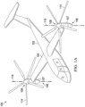
- FIGs. 1A and 1B illustrate an example electric tiltrotor aircraft 100 that is convertible between a helicopter mode (shown in FIG. 1A ), which allows for vertical takeoff and landing, hovering, and low speed directional movement, and an airplane mode (shown in FIG. 1B ), which allows for forward flight as well as horizontal takeoff and landing.
- Aircraft 100 includes a fuselage 102, wing 104, and a propulsion assemblies 106 rotatably coupled to wing 104 on opposite sides of the fuselage 102.
- Each propulsion assembly 106 includes a nacelle or pylon 107 and an open rotor assembly 108 including a plurality of rotor blades 114 connected to a rotor mast ( FIG.
- Each pylon 107 may house one or more electric motors therein configured to produce rotational energy that drives the rotation of rotor assembly 108.
- each pylon 107 may house a gearbox therein that drives the rotation of rotor assembly 108, wherein the gearbox receives rotational energy from a drive shaft.
- Propulsion assemblies 106 are each convertible, relative to fuselage 102, between a vertical position, as shown in FIG. 1A , and a horizontal position, as shown in FIG. 1B .
- Propulsion assemblies 106 are in the vertical position during vertical takeoff and landing mode. Vertical takeoff and landing mode may be considered to include hover operations of aircraft 100.
- Propulsion assemblies 106 are in the horizontal position during forward flight mode, in which aircraft 100 is in forward flight. In forward flight mode, propulsion assemblies 106 direct their respective thrusts in the aft direction to propel aircraft 100 forward.
- Aircraft 100 is operable to fly in all directions during the vertical takeoff and landing mode configuration of FIG. 1A , although faster forward flight is achievable while in the forward flight mode configuration of FIG. 1B .
- Propulsion assemblies 106 may be tiltable between the vertical and horizontal positions by a rotatable shafts (not shown) extending through wing 104 on opposite sides of fuselage 102 that are rotatable in response to commands originating from a pilot and/or a flight control system.
- Each of the propulsion assemblies 106 utilizes an electric motor and gearbox unit (described below) disposed within a respective rotatable pylon 107 as a power source to rotate the respective rotor assembly 108 about rotor axis via a rotor mast.
- Propulsion assemblies 106 are illustrated in the context of aircraft 100; however, propulsion assemblies 106 may be implemented on other types of tiltrotor aircraft.
- an alternative embodiment may include a quad tiltrotor that has an additional wing member aft of wing 104 that can have additional propulsion assemblies similar to propulsion assemblies 106.
- propulsion assemblies 106 may be implemented in connection with an unmanned version of aircraft 100. Further, propulsion assemblies 106 may be integrated into a variety of tiltrotor aircraft configurations.
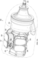
- each of the propulsion assemblies 106 includes a drive system 200 disposed within the pylon 107 for use as a power source for rotating the rotor system 108 about the rotor axis 116.
- the drive system 200 includes a gear box 202 and one or more electric motors 206 and associated power electronics 208.
- electric motors 206 may be implemented as radial flux motors.
- the motors 206 collectively drive (i.e., provide rotational power to) a drive shaft 210.
- Each of the motors 206 may be connected to the drive shaft 210 via a respective one of overrunning clutches 212, each of which transmits torque in one direction only and permits the drive shaft 210 to "freewheel," or continue to rotate, when the respective one of the motors 206 is stopped (e.g., upon failure of the motor).
- a forward end of drive shaft 210 is received within a receptacle 214 of the gearbox 202 for providing rotational power to a second drive shaft 216 disposed within gearbox 204 for driving gearbox gears 218.
- Gearbox gears 218 operate to transfer torque to a rotor shaft 220 connected to rotor assembly 108 ( FIGs. 1A and 1B ) for driving rotor assembly about rotor axis 116 ( FIGs. 1A and 1B ). It will be noted that, although drive system 200 is illustrated as including three electric motors, more or fewer motors may be included.
- gearbox 202 is directly driven by motors 206.
- an adapter 240 is provided between motors 206 and gearbox 202 for facilitating maintenance.
- adapter 240 enables motor assembly 206 and/or gearbox 202 to be removed (e.g., for maintenance) without requiring disassembly of all the major components from the nacelle.
- the adapter 240 is a structural component that includes a conversion spindle 240.
- the adapter 240 is positioned between or next to the gearbox 202 and motor assembly 206 and includes interfaces to attach to each separately.
- a shaft may span across the adapter to transmit the torque between the motor assembly and the gearbox; alternatively, the drive shaft could plug directly into the gearbox 202 through the adapter 240.
- the adapter may be configured in a variety of manners but comprises a structural member that supports multiple systems such that any one of them can be removed without substantially affecting the others.
- a spindle 242 may be integral to the adapter 240.
- spindle 242 may be attached to adapter 240 with a flange or other type of joint.
- gearbox 202 attaches to one side of the adapter 240 and the motors 206 attach to the opposite side of the adapter.
- pylon 107 rotatings relative to the wing 104 or other stationary structure about a tilt axis 230, which in the illustrated embodiment is located between electric motors 206 and gearbox 202, between a vertical position (e.g., as shown in FIG. 1A ) and a horizontal position (e.g., as shown in FIG. 1B ).
- motors 206 and gearbox 202 are coaxial.
- FIG. 3 illustrates an embodiment of aircraft 100' in which the tilt axis is located closer to the top/forward end of pylons 107'.
- FIG. 4 illustrates an embodiment of aircraft 100" in which the tilt axis is located closer to the bottom/aft end of pylons 107".
- propulsion system 106 provides flexibility in arrangement of electric motors 202.
- motors 202 may be configured as cylinders in series, stacked pancakes, or a flat pack.
- motors may be configured as cylinders in series ( FIG. 5A ), stacked pancakes ( FIG. 5B ), or a flat pack ( FIG. 5C ).
- FIG. 5A in the series arrangement, motors are stacked in line with the output shaft of the first motor in the series engaging the input shaft of the next motor in the series. The shafts may be engaged with one another by way of splines or another appropriate method.
- FIG. 5B in a pancake arrangement, multiple motors are stacked and engage a single output shaft. Motors can utilize different methods of engaging the output shaft, such as splines, bolted flanges, or other means.
- FIG. 5C in a flat pack arrangement, a combining gearbox is provided to combine inputs from the motors to a single output shaft.
- aircraft illustrated herein such as aircraft 100
- aircraft 100 is merely illustrative of a variety of aircraft that can implement the embodiments disclosed herein.
- the various embodiments of the electric drive system line replaceable unit described herein may be used on any aircraft that utilizes motors.
- Other aircraft implementations can include hybrid aircraft, tiltrotor aircraft, quad tiltrotor aircraft, unmanned aircraft, gyrocopters, airplanes, helicopters, commuter aircraft, electric aircraft, hybrid-electric aircraft, and the like.
- rotor assemblies 108 may comprise any materials suitable for use with an aircraft rotor.
- rotor blades 114 and other components may comprise carbon fiber or aluminum; and rotor masts 222 and other components may comprise steel or titanium.
- rotor assemblies 108 are shown with five rotor blades 114, respectively, it should be understood that they may have as few as two rotor blades and may have more than five rotor blades. Still further, while only two rotor assemblies 108 are depicted, it will be recognized that embodiments described herein may be implemented in connection with any number of rotor assemblies.
Landscapes
- Engineering & Computer Science (AREA)
- Aviation & Aerospace Engineering (AREA)
- Mechanical Engineering (AREA)
- Power Engineering (AREA)
- Retarders (AREA)
- Connection Of Motors, Electrical Generators, Mechanical Devices, And The Like (AREA)
Claims (8)
- Luftfahrzeug (100; 300; 400), das ein Rotorsystem umfasst, wobei das Rotorsystem Folgendes umfasst:eine offene Rotorbaugruppe (108; 308; 408), die eine Mehrzahl von Rotorblättern (114; 314; 414) umfasst, die über ein Joch mit einem Rotormast (222) verbunden sind, wobei die Rotorbaugruppe (108; 308; 408) relativ zu einem Flügel (104; 304; 404) des Luftfahrzeugs (100; 300; 400) zwischen einer ersten Position, die einem Flugzeugmodus des Luftfahrzeugs (100; 300; 400) entspricht, und einer zweiten Position, die einem Helikoptermodus des Luftfahrzeugs (100; 300; 400) entspricht, neigbar ist; undein Antriebssystem (200) zum Bereitstellen von Drehenergie zu der offenen Rotorbaugruppe (108; 308; 408) über den Rotormast (222), wobei das Antriebssystem (200) Folgendes umfasst:mindestens einen Elektromotor (206) zum Bereitstellen von Drehenergie zu einer Antriebswelle (210);ein Getriebe (202) zum Aufnehmen von Drehenergie von dem mindestens einen Elektromotor (206) über die Antriebswelle (210) und Bereitstellen von Drehenergie zu dem Rotormast (222) über eine Rotorwelle (220); undeinen Adapter (240), der zwischen dem mindestens einen Elektromotor (206) und dem Getriebe (202) zum Vereinfachen einer Wartung bereitgestellt ist, wobei:sich eine Welle über den Adapter (240) zum Übertragen von Drehmoment zwischen dem mindestens einen Elektromotor (206) und dem Getriebe (202) erstreckt oder die Antriebswelle (210) durch den Adapter (240) direkt in das Getriebe (202) gesteckt ist;der Adapter (240) eine erste Schnittfläche, die mit dem mindestens einen Elektromotor (206) verbunden ist, und eine zweite Schnittfläche umfasst, die mit dem Getriebe (202) derart verbunden ist, dass der mindestens eine Motor (206) und das Getriebe (202) entfernbar mit dem Adapter (240) gekoppelt sind;der Adapter (240) ein Strukturbauteil ist, das dazu ausgelegt ist, den mindestens einen Elektromotor (206) und das Getriebe (202) zu tragen; undder Adapter (240) eine Umwandlungsspindel (242) umfasst; wobei das Antriebssystem (200) relativ zu dem Flügel (104; 304; 404) um eine Neigungsachse (230) drehbar ist, wobei die Neigungsachse (230) mit einer Achse der Umwandlungsspindel (242) derart koaxial ist, dass das Antriebssystem (200) relativ zu dem Flügel (104; 304; 404) um die Achse der Umwandlungsspindel (242) drehbar ist; undwobei die Rotorwelle (220) mit der Antriebswelle (210) koaxial ist.
- Luftfahrzeug (100; 300; 400) nach Anspruch 1, wobei sich die Neigungsachse (230) näher an einem vorderen Ende des Antriebssystems (200) als an einem hinteren Ende des Antriebssystems (200) befindet.
- Luftfahrzeug (100; 300; 400) nach Anspruch 1, wobei sich die Neigungsachse (230) näher an einem hinteren Ende des Antriebssystems (200) als an einem vorderen Ende des Antriebssystems (200) befindet.
- Luftfahrzeug (100; 300; 400) nach einem der vorhergehenden Ansprüche, wobei der mindestens eine Elektromotor (206) eine Mehrzahl von Elektromotoren umfasst, die als Zylinder in Reihe angeordnet sind, wobei ein Ausgang eines ersten der Mehrzahl von Elektromotoren mit einem Eingang eines nächsten der Mehrzahl von Elektromotoren in Eingriff steht.
- Luftfahrzeug (100; 300; 400) nach einem der Ansprüche 1 bis 3, wobei der mindestens eine Elektromotor (206) eine Mehrzahl von Elektromotoren umfasst, die als gestapelte Scheiben angeordnet sind, wobei alle der Mehrzahl von Elektromotoren mit einer einzelnen Antriebswelle (210) in Eingriff stehen.
- Luftfahrzeug (100; 300; 400) nach einem der Ansprüche 1 bis 3, wobei der mindestens eine Elektromotor eine Mehrzahl von Elektromotoren umfasst, die als ein Flachgehäuse angeordnet sind, wobei Ausgänge der Mehrzahl von Elektromotoren mit Eingängen eines verbindenden Getriebes zum Antreiben einer Antriebswelle (210) in Eingriff stehen.
- Luftfahrzeug (100; 300; 400) nach einem der vorhergehenden Ansprüche, ferner umfassend eine Gondel (107; 307; 407), in der das Antriebssystem (200) untergebracht ist, wobei die Gondel (107; 307; 407) an der Neigungsachse (230) drehbar mit dem Flügel (104; 304; 404) des Luftfahrzeugs (100; 300; 400) verbunden ist.
- Luftfahrzeug (100; 300; 400) nach einem der vorhergehenden Ansprüche, wobei der mindestens eine Motor (206) über eine Freilaufkupplung (212) mit der Antriebswelle (210) verbunden ist.
Priority Applications (1)
| Application Number | Priority Date | Filing Date | Title |
|---|---|---|---|
| EP24163761.0A EP4361032B1 (de) | 2021-01-13 | 2021-11-12 | Antriebssystem zur bereitstellung von rotationsenergie für eine rotoranordnung eines drehflügelflugzeugs |
Applications Claiming Priority (1)
| Application Number | Priority Date | Filing Date | Title |
|---|---|---|---|
| US17/148,307 US11814163B2 (en) | 2021-01-13 | 2021-01-13 | Electric tiltrotor aircraft with tilting coaxial motors and gearbox |
Related Child Applications (2)
| Application Number | Title | Priority Date | Filing Date |
|---|---|---|---|
| EP24163761.0A Division-Into EP4361032B1 (de) | 2021-01-13 | 2021-11-12 | Antriebssystem zur bereitstellung von rotationsenergie für eine rotoranordnung eines drehflügelflugzeugs |
| EP24163761.0A Division EP4361032B1 (de) | 2021-01-13 | 2021-11-12 | Antriebssystem zur bereitstellung von rotationsenergie für eine rotoranordnung eines drehflügelflugzeugs |
Publications (2)
| Publication Number | Publication Date |
|---|---|
| EP4029779A1 EP4029779A1 (de) | 2022-07-20 |
| EP4029779B1 true EP4029779B1 (de) | 2024-07-17 |
Family
ID=78617273
Family Applications (2)
| Application Number | Title | Priority Date | Filing Date |
|---|---|---|---|
| EP24163761.0A Active EP4361032B1 (de) | 2021-01-13 | 2021-11-12 | Antriebssystem zur bereitstellung von rotationsenergie für eine rotoranordnung eines drehflügelflugzeugs |
| EP21207937.0A Active EP4029779B1 (de) | 2021-01-13 | 2021-11-12 | Elektrisches kipprotorflugzeug mit kippbaren koaxialen motoren und getriebe |
Family Applications Before (1)
| Application Number | Title | Priority Date | Filing Date |
|---|---|---|---|
| EP24163761.0A Active EP4361032B1 (de) | 2021-01-13 | 2021-11-12 | Antriebssystem zur bereitstellung von rotationsenergie für eine rotoranordnung eines drehflügelflugzeugs |
Country Status (2)
| Country | Link |
|---|---|
| US (2) | US11814163B2 (de) |
| EP (2) | EP4361032B1 (de) |
Families Citing this family (2)
| Publication number | Priority date | Publication date | Assignee | Title |
|---|---|---|---|---|
| FR3137894A1 (fr) * | 2022-07-13 | 2024-01-19 | Airbus (S.A.S.) | Ensemble de propulsion électrique comportant au moins un moteur électrique positionné à l’avant d’un système de transmission, aéronef comportant au moins un tel ensemble de propulsion |
| US11787551B1 (en) * | 2022-10-06 | 2023-10-17 | Archer Aviation, Inc. | Vertical takeoff and landing aircraft electric engine configuration |
Citations (1)
| Publication number | Priority date | Publication date | Assignee | Title |
|---|---|---|---|---|
| WO2010123601A1 (en) * | 2009-01-27 | 2010-10-28 | Kuhn Ira F Jr | Purebred and hybrid electric vtol tilt rotor aircraft |
Family Cites Families (67)
| Publication number | Priority date | Publication date | Assignee | Title |
|---|---|---|---|---|
| GB1322169A (en) * | 1969-07-23 | 1973-07-04 | Kisovec A V | Convertiplanes |
| US4168459A (en) | 1977-10-25 | 1979-09-18 | Precise Power Corporation | Non-interruptible power supply systems |
| US4476395A (en) | 1981-10-19 | 1984-10-09 | Lockheed Corporation | Tandem-generator design for aircraft |
| US4757224A (en) | 1985-04-26 | 1988-07-12 | Magnetics Research International Corp. | Full flux reversal variable reluctance machine |
| US5990590A (en) | 1996-09-10 | 1999-11-23 | Precise Power Corporation | Versatile AC dynamo-electric machine |
| US6655631B2 (en) * | 2000-07-28 | 2003-12-02 | John Frederick Austen-Brown | Personal hoverplane with four tiltmotors |
| US6700252B2 (en) | 2000-12-21 | 2004-03-02 | Schlumberger Technology Corp. | Field configurable modular motor |
| WO2004027211A1 (en) | 2002-09-18 | 2004-04-01 | Philip Head | Electric motors for powering downhole tools |
| US6719244B1 (en) * | 2003-02-03 | 2004-04-13 | Gary Robert Gress | VTOL aircraft control using opposed tilting of its dual propellers or fans |
| US6906413B2 (en) | 2003-05-30 | 2005-06-14 | Honeywell International Inc. | Integrated heat spreader lid |
| GB0327023D0 (en) | 2003-11-20 | 2003-12-24 | Head Philip | Electric motors for powering downhole tools |
| CN101027215A (zh) * | 2004-09-30 | 2007-08-29 | 贝尔直升机泰克斯特龙公司 | 紧凑倾转旋翼吊架转换驱动系统 |
| US7309938B1 (en) | 2006-05-31 | 2007-12-18 | Smith Kelly S | Rotary power converter |
| CA2935518A1 (en) | 2008-03-24 | 2009-10-01 | Prime Datum, Inc. | Integrated fan drive system for air-cooled heat exchangers (ache) |
| WO2009126905A1 (en) * | 2008-04-11 | 2009-10-15 | Karem Aircraft, Inc. | Tilt actuation for a rotorcraft |
| GB0903423D0 (en) | 2009-03-02 | 2009-04-08 | Rolls Royce Plc | Variable drive gas turbine engine |
| US8169110B2 (en) | 2009-10-09 | 2012-05-01 | GM Global Technology Operations LLC | Oil cooled motor/generator for an automotive powertrain |
| NO330820B1 (no) | 2009-12-24 | 2011-07-25 | Prox Dynamics As | Rotormekanisme for helikoptere |
| CN101837195B (zh) * | 2010-01-21 | 2012-02-08 | 罗之洪 | 一种垂直起降的模型飞机 |
| TWI401862B (zh) | 2010-07-15 | 2013-07-11 | Univ Nat Cheng Kung | 馬達及電子裝置 |
| GB2491129B (en) | 2011-05-23 | 2014-04-23 | Blue Bear Systems Res Ltd | Air vehicle |
| KR101294071B1 (ko) | 2011-10-27 | 2013-08-07 | 현대자동차주식회사 | 하이브리드 차량용 시스템 |
| TWM439948U (en) | 2012-06-26 | 2012-10-21 | Yen Shen Electric Ind Co Ltd | Motor of built-in actuator |
| JP2014121255A (ja) | 2012-12-12 | 2014-06-30 | Hyundai Motor Company Co Ltd | 環境に優しい自動車の駆動モータ、及びこの駆動モータの回転子構造 |
| US9126678B2 (en) * | 2013-03-13 | 2015-09-08 | Bell Helicopter Textron Inc. | Spindle mounted tiltrotor pylon with fixed engine arrangement |
| US9327831B2 (en) | 2013-05-22 | 2016-05-03 | Bell Helicopter Textron Inc. | Rotorcraft flapping lock |
| GB201320246D0 (en) | 2013-11-15 | 2014-01-01 | Coreteq Ltd | Line start permanent magnet motor using a modular rotor |
| WO2015192040A1 (en) | 2014-06-13 | 2015-12-17 | Tolomatic, Inc. | Coupled capacitive and magnetic servo motor systems |
| US10023318B2 (en) | 2014-07-17 | 2018-07-17 | Japan Aerospace Exploration Agency | Motorized aircraft and method for determining output and number of electric motors in motorized aircraft |
| IL233942B (en) | 2014-08-04 | 2020-01-30 | Israel Aerospace Ind Ltd | Assembly of the drive system |
| DE102014014588A1 (de) | 2014-10-01 | 2016-04-07 | Liebherr-Aerospace Lindenberg Gmbh | Redundanter modularer Schwenkwinkelmotor |
| DE102015222792A1 (de) | 2015-11-18 | 2017-05-18 | Baumüller Nürnberg GmbH | Motorbaugruppe |
| US20170327219A1 (en) * | 2015-12-11 | 2017-11-16 | Sikorsky Aircraft Corporation | Vertical take-off and landing aircraft with hybrid power and method |
| US10926874B2 (en) | 2016-01-15 | 2021-02-23 | Aurora Flight Sciences Corporation | Hybrid propulsion vertical take-off and landing aircraft |
| US10199907B2 (en) | 2016-02-24 | 2019-02-05 | Ge Aviation Systems Llc | Method and assembly of a power generation system |
| CN109565220B (zh) | 2016-06-10 | 2022-04-26 | 菲舍尔和佩克尔应用有限公司 | 直接传动电动机布置 |
| US10737765B2 (en) | 2016-07-01 | 2020-08-11 | Textron Innovations Inc. | Aircraft having single-axis gimbal mounted propulsion systems |
| US10625853B2 (en) | 2016-07-01 | 2020-04-21 | Textron Innovations Inc. | Automated configuration of mission specific aircraft |
| US10700579B2 (en) | 2016-07-20 | 2020-06-30 | Ge Aviation Systems Llc | Method and assembly of a generator |
| US10106253B2 (en) | 2016-08-31 | 2018-10-23 | Bell Helicopter Textron Inc. | Tilting ducted fan aircraft generating a pitch control moment |
| US10800539B2 (en) | 2016-08-19 | 2020-10-13 | General Electric Company | Propulsion engine for an aircraft |
| NO342415B1 (en) | 2016-08-31 | 2018-05-22 | FLIR Unmanned Aerial Systems AS | Controlling blade pitch by a plurality of electric motors |
| US10252797B2 (en) | 2016-09-08 | 2019-04-09 | General Electric Company | Tiltrotor propulsion system for an aircraft |
| DE102016220234A1 (de) | 2016-10-17 | 2018-04-19 | Siemens Aktiengesellschaft | Trennkupplungsvorrichtung zur Fehlerbehebung einer elektrischen Maschine |
| US11731772B2 (en) | 2017-03-02 | 2023-08-22 | Textron Innovations Inc. | Hybrid propulsion drive train system for tiltrotor aircraft |
| JP6447662B2 (ja) | 2017-05-09 | 2019-01-09 | ダイキン工業株式会社 | 電動機システムおよびそれを備えたターボ圧縮機 |
| US10730622B2 (en) | 2017-06-14 | 2020-08-04 | Bell Helicopter Textron Inc. | Personal air vehicle with ducted fans |
| US10689106B2 (en) * | 2017-07-06 | 2020-06-23 | Bell Helicopter Textron Inc. | Fixed outboard engine tiltrotor with leading edge drive system and angled rotation spindle configuration |
| CN111065577A (zh) | 2017-08-23 | 2020-04-24 | 维曼机器人股份有限公司 | 驱动机构 |
| US10988247B2 (en) | 2017-10-19 | 2021-04-27 | Uvionix Aerospace Corporation | Unmanned aerial vehicle and propulsion system for an unmanned aerial vehicle |
| US20190135427A1 (en) | 2017-11-09 | 2019-05-09 | Bell Helicopter Textron Inc. | Tri-rotor tailsitter aircraft |
| US10752373B2 (en) | 2017-11-16 | 2020-08-25 | Textron Innovation Inc. | Air management systems for stacked motor assemblies |
| US10418868B1 (en) | 2018-02-09 | 2019-09-17 | Kitty Hawk Corporation | Modular motor assembly |
| US20190288571A1 (en) | 2018-02-20 | 2019-09-19 | Wright Electric Inc. | Electric motors for aircraft propulsion and associated systems and methods |
| US20190270516A1 (en) | 2018-03-01 | 2019-09-05 | Bell Helicopter Textron Inc. | Propulsion Systems for Rotorcraft |
| CN112313147B (zh) | 2018-03-16 | 2025-07-22 | 杰欧比飞行有限公司 | 飞行器减阻系统和内部冷却电动马达系统及使用它们的飞行器 |
| US11060562B2 (en) | 2018-04-01 | 2021-07-13 | Textron Innovations Inc. | Axially actuated locking system for a retractable driveshaft and method for use thereof |
| US10926873B2 (en) | 2018-06-20 | 2021-02-23 | Lockheed Martin Corporation | Electric powered direct drive rotor motor with integrated mechanical flight control |
| US11613375B2 (en) | 2019-05-16 | 2023-03-28 | Textron Innovations Inc. | Dual motor input with overrunning clutch |
| US12191722B2 (en) | 2019-05-31 | 2025-01-07 | MagniX USA, Inc. | High-torque electric motor assembly |
| JP7265957B2 (ja) | 2019-08-06 | 2023-04-27 | 株式会社Subaru | 冗長系推進装置及び電動航空機 |
| US11738862B2 (en) * | 2020-01-28 | 2023-08-29 | Overair, Inc. | Fail-operational vtol aircraft |
| US11565803B2 (en) | 2020-03-04 | 2023-01-31 | Textron Innovations Inc. | Electric drive system line replaceable unit with integrated cyclic actuation |
| US11831220B2 (en) | 2020-06-22 | 2023-11-28 | Textron Innovations Inc. | Electric motor stack with integral one-piece gearbox input shaft |
| US11702196B2 (en) * | 2020-06-25 | 2023-07-18 | Textron Innovations Inc. | Rotor system with reconfigurable duct |
| US11390395B2 (en) | 2020-06-25 | 2022-07-19 | Textron Innovations Inc. | Aircraft rotor assembly with segmented input shaft for electric motor stack and gearbox unit |
| US11420760B2 (en) | 2020-06-29 | 2022-08-23 | Textron Innovations Inc. | Sealed coaxial input and output shafts |
-
2021
- 2021-01-13 US US17/148,307 patent/US11814163B2/en active Active
- 2021-11-12 EP EP24163761.0A patent/EP4361032B1/de active Active
- 2021-11-12 EP EP21207937.0A patent/EP4029779B1/de active Active
-
2023
- 2023-10-03 US US18/480,338 patent/US12473083B2/en active Active
Patent Citations (1)
| Publication number | Priority date | Publication date | Assignee | Title |
|---|---|---|---|---|
| WO2010123601A1 (en) * | 2009-01-27 | 2010-10-28 | Kuhn Ira F Jr | Purebred and hybrid electric vtol tilt rotor aircraft |
Also Published As
| Publication number | Publication date |
|---|---|
| US20220219817A1 (en) | 2022-07-14 |
| US12473083B2 (en) | 2025-11-18 |
| EP4361032B1 (de) | 2025-12-31 |
| EP4029779A1 (de) | 2022-07-20 |
| EP4361032A3 (de) | 2024-07-31 |
| EP4361032A2 (de) | 2024-05-01 |
| US11814163B2 (en) | 2023-11-14 |
| US20240025542A1 (en) | 2024-01-25 |
Similar Documents
| Publication | Publication Date | Title |
|---|---|---|
| US11970283B2 (en) | Dual motor input with overrunning clutch | |
| US11142310B2 (en) | Dual tiltwing aircraft having a quadrilateral linkage | |
| EP3299290B1 (de) | Rotierende proprotoranordnung für ein kipprotorflugzeug | |
| EP3495260B1 (de) | Doppelrotorantriebssysteme für kipprotorflugzeug | |
| EP3486168B1 (de) | Kipprotorflugzeug mit erweiterter reichweite | |
| EP4036002B1 (de) | Elektrisches kipprotorflugzeug mit feststehenden motoren | |
| EP3875375B1 (de) | Rotorsystem mit einer taumelscheibe und einem elektrischen antriebssystem als eine einzige integrierte einheit. | |
| EP3929089B1 (de) | Elektromotorstapel mit integrierter einteiliger getriebeeingangswelle | |
| EP3290338B1 (de) | Flugzeug mit fähigkeiten zur rotor-zu-flügel-umwandlung | |
| EP4091940B1 (de) | Elektrisches kipprotorflugzeug | |
| EP3876400A1 (de) | Elektrische antriebssystem austauscheinheit mit integrierter thermischer kühlung | |
| CN111003166A (zh) | 一种纵列式电动双旋翼直升机及其控制系统 | |
| US20230234703A1 (en) | Convertiplane with stopped rotors, and repositionable rotor blades | |
| US20190023383A1 (en) | Tilting coaxial rotor for a rotary wing aircraft | |
| EP3587258B1 (de) | Motor und drehbare proprotorkonfigurationen für ein kipprotorflugzeug | |
| RU2548304C1 (ru) | Многовинтовой преобразуемый скоростной вертолет | |
| US12473083B2 (en) | Electric tiltrotor aircraft with tilting coaxial motors and gearbox | |
| RU2521090C1 (ru) | Скоростной турбоэлектрический вертолет | |
| US11807357B2 (en) | Tilting hexrotor aircraft | |
| CN107685856B (zh) | 碟形飞行机 | |
| US11772804B2 (en) | Electric tiltrotor aircraft with offset tilting motors | |
| CN211642595U (zh) | 一种纵列式电动双旋翼直升机 | |
| CN120986666A (zh) | 一种可垂直起降的自旋翼机及其控制方法 |
Legal Events
| Date | Code | Title | Description |
|---|---|---|---|
| PUAI | Public reference made under article 153(3) epc to a published international application that has entered the european phase |
Free format text: ORIGINAL CODE: 0009012 |
|
| STAA | Information on the status of an ep patent application or granted ep patent |
Free format text: STATUS: EXAMINATION IS IN PROGRESS |
|
| 17P | Request for examination filed |
Effective date: 20211112 |
|
| AK | Designated contracting states |
Kind code of ref document: A1 Designated state(s): AL AT BE BG CH CY CZ DE DK EE ES FI FR GB GR HR HU IE IS IT LI LT LU LV MC MK MT NL NO PL PT RO RS SE SI SK SM TR |
|
| REG | Reference to a national code |
Ref country code: DE Ref legal event code: R079 Free format text: PREVIOUS MAIN CLASS: B64C0027120000 Ipc: F16H0001280000 Ref document number: 602021015760 Country of ref document: DE |
|
| GRAP | Despatch of communication of intention to grant a patent |
Free format text: ORIGINAL CODE: EPIDOSNIGR1 |
|
| RIC1 | Information provided on ipc code assigned before grant |
Ipc: B64C 27/12 20060101ALI20230918BHEP Ipc: B64D 35/02 20060101ALI20230918BHEP Ipc: B64D 27/24 20060101ALI20230918BHEP Ipc: F16H 1/28 20060101AFI20230918BHEP |
|
| STAA | Information on the status of an ep patent application or granted ep patent |
Free format text: STATUS: GRANT OF PATENT IS INTENDED |
|
| INTG | Intention to grant announced |
Effective date: 20231026 |
|
| GRAJ | Information related to disapproval of communication of intention to grant by the applicant or resumption of examination proceedings by the epo deleted |
Free format text: ORIGINAL CODE: EPIDOSDIGR1 |
|
| STAA | Information on the status of an ep patent application or granted ep patent |
Free format text: STATUS: EXAMINATION IS IN PROGRESS |
|
| RAP1 | Party data changed (applicant data changed or rights of an application transferred) |
Owner name: TEXTRON INNOVATIONS INC. |
|
| GRAP | Despatch of communication of intention to grant a patent |
Free format text: ORIGINAL CODE: EPIDOSNIGR1 |
|
| STAA | Information on the status of an ep patent application or granted ep patent |
Free format text: STATUS: GRANT OF PATENT IS INTENDED |
|
| INTC | Intention to grant announced (deleted) | ||
| INTG | Intention to grant announced |
Effective date: 20240226 |
|
| GRAS | Grant fee paid |
Free format text: ORIGINAL CODE: EPIDOSNIGR3 |
|
| GRAA | (expected) grant |
Free format text: ORIGINAL CODE: 0009210 |
|
| STAA | Information on the status of an ep patent application or granted ep patent |
Free format text: STATUS: THE PATENT HAS BEEN GRANTED |
|
| AK | Designated contracting states |
Kind code of ref document: B1 Designated state(s): AL AT BE BG CH CY CZ DE DK EE ES FI FR GB GR HR HU IE IS IT LI LT LU LV MC MK MT NL NO PL PT RO RS SE SI SK SM TR |
|
| REG | Reference to a national code |
Ref country code: CH Ref legal event code: EP |
|
| REG | Reference to a national code |
Ref country code: DE Ref legal event code: R096 Ref document number: 602021015760 Country of ref document: DE |
|
| REG | Reference to a national code |
Ref country code: IE Ref legal event code: FG4D |
|
| REG | Reference to a national code |
Ref country code: LT Ref legal event code: MG9D |
|
| REG | Reference to a national code |
Ref country code: NL Ref legal event code: MP Effective date: 20240717 |
|
| PG25 | Lapsed in a contracting state [announced via postgrant information from national office to epo] |
Ref country code: PT Free format text: LAPSE BECAUSE OF FAILURE TO SUBMIT A TRANSLATION OF THE DESCRIPTION OR TO PAY THE FEE WITHIN THE PRESCRIBED TIME-LIMIT Effective date: 20241118 |
|
| REG | Reference to a national code |
Ref country code: AT Ref legal event code: MK05 Ref document number: 1704416 Country of ref document: AT Kind code of ref document: T Effective date: 20240717 |
|
| PG25 | Lapsed in a contracting state [announced via postgrant information from national office to epo] |
Ref country code: NL Free format text: LAPSE BECAUSE OF FAILURE TO SUBMIT A TRANSLATION OF THE DESCRIPTION OR TO PAY THE FEE WITHIN THE PRESCRIBED TIME-LIMIT Effective date: 20240717 |
|
| PG25 | Lapsed in a contracting state [announced via postgrant information from national office to epo] |
Ref country code: PT Free format text: LAPSE BECAUSE OF FAILURE TO SUBMIT A TRANSLATION OF THE DESCRIPTION OR TO PAY THE FEE WITHIN THE PRESCRIBED TIME-LIMIT Effective date: 20241118 Ref country code: NL Free format text: LAPSE BECAUSE OF FAILURE TO SUBMIT A TRANSLATION OF THE DESCRIPTION OR TO PAY THE FEE WITHIN THE PRESCRIBED TIME-LIMIT Effective date: 20240717 |
|
| PG25 | Lapsed in a contracting state [announced via postgrant information from national office to epo] |
Ref country code: NO Free format text: LAPSE BECAUSE OF FAILURE TO SUBMIT A TRANSLATION OF THE DESCRIPTION OR TO PAY THE FEE WITHIN THE PRESCRIBED TIME-LIMIT Effective date: 20241017 |
|
| PG25 | Lapsed in a contracting state [announced via postgrant information from national office to epo] |
Ref country code: PL Free format text: LAPSE BECAUSE OF FAILURE TO SUBMIT A TRANSLATION OF THE DESCRIPTION OR TO PAY THE FEE WITHIN THE PRESCRIBED TIME-LIMIT Effective date: 20240717 Ref country code: FI Free format text: LAPSE BECAUSE OF FAILURE TO SUBMIT A TRANSLATION OF THE DESCRIPTION OR TO PAY THE FEE WITHIN THE PRESCRIBED TIME-LIMIT Effective date: 20240717 Ref country code: GR Free format text: LAPSE BECAUSE OF FAILURE TO SUBMIT A TRANSLATION OF THE DESCRIPTION OR TO PAY THE FEE WITHIN THE PRESCRIBED TIME-LIMIT Effective date: 20241018 |
|
| PG25 | Lapsed in a contracting state [announced via postgrant information from national office to epo] |
Ref country code: BG Free format text: LAPSE BECAUSE OF FAILURE TO SUBMIT A TRANSLATION OF THE DESCRIPTION OR TO PAY THE FEE WITHIN THE PRESCRIBED TIME-LIMIT Effective date: 20240717 |
|
| PG25 | Lapsed in a contracting state [announced via postgrant information from national office to epo] |
Ref country code: LV Free format text: LAPSE BECAUSE OF FAILURE TO SUBMIT A TRANSLATION OF THE DESCRIPTION OR TO PAY THE FEE WITHIN THE PRESCRIBED TIME-LIMIT Effective date: 20240717 |
|
| PG25 | Lapsed in a contracting state [announced via postgrant information from national office to epo] |
Ref country code: IS Free format text: LAPSE BECAUSE OF FAILURE TO SUBMIT A TRANSLATION OF THE DESCRIPTION OR TO PAY THE FEE WITHIN THE PRESCRIBED TIME-LIMIT Effective date: 20241117 Ref country code: AT Free format text: LAPSE BECAUSE OF FAILURE TO SUBMIT A TRANSLATION OF THE DESCRIPTION OR TO PAY THE FEE WITHIN THE PRESCRIBED TIME-LIMIT Effective date: 20240717 |
|
| PG25 | Lapsed in a contracting state [announced via postgrant information from national office to epo] |
Ref country code: HR Free format text: LAPSE BECAUSE OF FAILURE TO SUBMIT A TRANSLATION OF THE DESCRIPTION OR TO PAY THE FEE WITHIN THE PRESCRIBED TIME-LIMIT Effective date: 20240717 |
|
| PG25 | Lapsed in a contracting state [announced via postgrant information from national office to epo] |
Ref country code: RS Free format text: LAPSE BECAUSE OF FAILURE TO SUBMIT A TRANSLATION OF THE DESCRIPTION OR TO PAY THE FEE WITHIN THE PRESCRIBED TIME-LIMIT Effective date: 20241017 Ref country code: ES Free format text: LAPSE BECAUSE OF FAILURE TO SUBMIT A TRANSLATION OF THE DESCRIPTION OR TO PAY THE FEE WITHIN THE PRESCRIBED TIME-LIMIT Effective date: 20240717 |
|
| PG25 | Lapsed in a contracting state [announced via postgrant information from national office to epo] |
Ref country code: RS Free format text: LAPSE BECAUSE OF FAILURE TO SUBMIT A TRANSLATION OF THE DESCRIPTION OR TO PAY THE FEE WITHIN THE PRESCRIBED TIME-LIMIT Effective date: 20241017 Ref country code: PL Free format text: LAPSE BECAUSE OF FAILURE TO SUBMIT A TRANSLATION OF THE DESCRIPTION OR TO PAY THE FEE WITHIN THE PRESCRIBED TIME-LIMIT Effective date: 20240717 Ref country code: NO Free format text: LAPSE BECAUSE OF FAILURE TO SUBMIT A TRANSLATION OF THE DESCRIPTION OR TO PAY THE FEE WITHIN THE PRESCRIBED TIME-LIMIT Effective date: 20241017 Ref country code: LV Free format text: LAPSE BECAUSE OF FAILURE TO SUBMIT A TRANSLATION OF THE DESCRIPTION OR TO PAY THE FEE WITHIN THE PRESCRIBED TIME-LIMIT Effective date: 20240717 Ref country code: IS Free format text: LAPSE BECAUSE OF FAILURE TO SUBMIT A TRANSLATION OF THE DESCRIPTION OR TO PAY THE FEE WITHIN THE PRESCRIBED TIME-LIMIT Effective date: 20241117 Ref country code: HR Free format text: LAPSE BECAUSE OF FAILURE TO SUBMIT A TRANSLATION OF THE DESCRIPTION OR TO PAY THE FEE WITHIN THE PRESCRIBED TIME-LIMIT Effective date: 20240717 Ref country code: GR Free format text: LAPSE BECAUSE OF FAILURE TO SUBMIT A TRANSLATION OF THE DESCRIPTION OR TO PAY THE FEE WITHIN THE PRESCRIBED TIME-LIMIT Effective date: 20241018 Ref country code: FI Free format text: LAPSE BECAUSE OF FAILURE TO SUBMIT A TRANSLATION OF THE DESCRIPTION OR TO PAY THE FEE WITHIN THE PRESCRIBED TIME-LIMIT Effective date: 20240717 Ref country code: ES Free format text: LAPSE BECAUSE OF FAILURE TO SUBMIT A TRANSLATION OF THE DESCRIPTION OR TO PAY THE FEE WITHIN THE PRESCRIBED TIME-LIMIT Effective date: 20240717 Ref country code: BG Free format text: LAPSE BECAUSE OF FAILURE TO SUBMIT A TRANSLATION OF THE DESCRIPTION OR TO PAY THE FEE WITHIN THE PRESCRIBED TIME-LIMIT Effective date: 20240717 Ref country code: AT Free format text: LAPSE BECAUSE OF FAILURE TO SUBMIT A TRANSLATION OF THE DESCRIPTION OR TO PAY THE FEE WITHIN THE PRESCRIBED TIME-LIMIT Effective date: 20240717 |
|
| PG25 | Lapsed in a contracting state [announced via postgrant information from national office to epo] |
Ref country code: RO Free format text: LAPSE BECAUSE OF FAILURE TO SUBMIT A TRANSLATION OF THE DESCRIPTION OR TO PAY THE FEE WITHIN THE PRESCRIBED TIME-LIMIT Effective date: 20240717 Ref country code: DK Free format text: LAPSE BECAUSE OF FAILURE TO SUBMIT A TRANSLATION OF THE DESCRIPTION OR TO PAY THE FEE WITHIN THE PRESCRIBED TIME-LIMIT Effective date: 20240717 Ref country code: SM Free format text: LAPSE BECAUSE OF FAILURE TO SUBMIT A TRANSLATION OF THE DESCRIPTION OR TO PAY THE FEE WITHIN THE PRESCRIBED TIME-LIMIT Effective date: 20240717 |
|
| REG | Reference to a national code |
Ref country code: DE Ref legal event code: R097 Ref document number: 602021015760 Country of ref document: DE |
|
| PG25 | Lapsed in a contracting state [announced via postgrant information from national office to epo] |
Ref country code: EE Free format text: LAPSE BECAUSE OF FAILURE TO SUBMIT A TRANSLATION OF THE DESCRIPTION OR TO PAY THE FEE WITHIN THE PRESCRIBED TIME-LIMIT Effective date: 20240717 |
|
| PG25 | Lapsed in a contracting state [announced via postgrant information from national office to epo] |
Ref country code: CZ Free format text: LAPSE BECAUSE OF FAILURE TO SUBMIT A TRANSLATION OF THE DESCRIPTION OR TO PAY THE FEE WITHIN THE PRESCRIBED TIME-LIMIT Effective date: 20240717 |
|
| PG25 | Lapsed in a contracting state [announced via postgrant information from national office to epo] |
Ref country code: SK Free format text: LAPSE BECAUSE OF FAILURE TO SUBMIT A TRANSLATION OF THE DESCRIPTION OR TO PAY THE FEE WITHIN THE PRESCRIBED TIME-LIMIT Effective date: 20240717 |
|
| PLBE | No opposition filed within time limit |
Free format text: ORIGINAL CODE: 0009261 |
|
| STAA | Information on the status of an ep patent application or granted ep patent |
Free format text: STATUS: NO OPPOSITION FILED WITHIN TIME LIMIT |
|
| 26N | No opposition filed |
Effective date: 20250422 |
|
| REG | Reference to a national code |
Ref country code: CH Ref legal event code: PL |
|
| PG25 | Lapsed in a contracting state [announced via postgrant information from national office to epo] |
Ref country code: MC Free format text: LAPSE BECAUSE OF FAILURE TO SUBMIT A TRANSLATION OF THE DESCRIPTION OR TO PAY THE FEE WITHIN THE PRESCRIBED TIME-LIMIT Effective date: 20240717 |
|
| PG25 | Lapsed in a contracting state [announced via postgrant information from national office to epo] |
Ref country code: LU Free format text: LAPSE BECAUSE OF NON-PAYMENT OF DUE FEES Effective date: 20241112 |
|
| REG | Reference to a national code |
Ref country code: CH Ref legal event code: PL |
|
| PG25 | Lapsed in a contracting state [announced via postgrant information from national office to epo] |
Ref country code: CH Free format text: LAPSE BECAUSE OF NON-PAYMENT OF DUE FEES Effective date: 20241130 |
|
| REG | Reference to a national code |
Ref country code: BE Ref legal event code: MM Effective date: 20241130 |
|
| PG25 | Lapsed in a contracting state [announced via postgrant information from national office to epo] |
Ref country code: SE Free format text: LAPSE BECAUSE OF FAILURE TO SUBMIT A TRANSLATION OF THE DESCRIPTION OR TO PAY THE FEE WITHIN THE PRESCRIBED TIME-LIMIT Effective date: 20240717 |
|
| PG25 | Lapsed in a contracting state [announced via postgrant information from national office to epo] |
Ref country code: BE Free format text: LAPSE BECAUSE OF NON-PAYMENT OF DUE FEES Effective date: 20241130 |
|
| PG25 | Lapsed in a contracting state [announced via postgrant information from national office to epo] |
Ref country code: IE Free format text: LAPSE BECAUSE OF NON-PAYMENT OF DUE FEES Effective date: 20241112 |
|
| PGFP | Annual fee paid to national office [announced via postgrant information from national office to epo] |
Ref country code: DE Payment date: 20251128 Year of fee payment: 5 |
|
| PGFP | Annual fee paid to national office [announced via postgrant information from national office to epo] |
Ref country code: GB Payment date: 20251127 Year of fee payment: 5 |
|
| PGFP | Annual fee paid to national office [announced via postgrant information from national office to epo] |
Ref country code: FR Payment date: 20251125 Year of fee payment: 5 |
|
| PG25 | Lapsed in a contracting state [announced via postgrant information from national office to epo] |
Ref country code: IT Free format text: LAPSE BECAUSE OF FAILURE TO SUBMIT A TRANSLATION OF THE DESCRIPTION OR TO PAY THE FEE WITHIN THE PRESCRIBED TIME-LIMIT Effective date: 20240717 |
|
| PG25 | Lapsed in a contracting state [announced via postgrant information from national office to epo] |
Ref country code: HU Free format text: LAPSE BECAUSE OF FAILURE TO SUBMIT A TRANSLATION OF THE DESCRIPTION OR TO PAY THE FEE WITHIN THE PRESCRIBED TIME-LIMIT; INVALID AB INITIO Effective date: 20211112 |
|
| PG25 | Lapsed in a contracting state [announced via postgrant information from national office to epo] |
Ref country code: CY Free format text: LAPSE BECAUSE OF FAILURE TO SUBMIT A TRANSLATION OF THE DESCRIPTION OR TO PAY THE FEE WITHIN THE PRESCRIBED TIME-LIMIT; INVALID AB INITIO Effective date: 20211112 |