EP0292103B1 - Bobine de mesure à fibre optique - Google Patents
Bobine de mesure à fibre optique Download PDFInfo
- Publication number
- EP0292103B1 EP0292103B1 EP88302679A EP88302679A EP0292103B1 EP 0292103 B1 EP0292103 B1 EP 0292103B1 EP 88302679 A EP88302679 A EP 88302679A EP 88302679 A EP88302679 A EP 88302679A EP 0292103 B1 EP0292103 B1 EP 0292103B1
- Authority
- EP
- European Patent Office
- Prior art keywords
- coil
- fiber
- spool
- turns
- layers
- Prior art date
- Legal status (The legal status is an assumption and is not a legal conclusion. Google has not performed a legal analysis and makes no representation as to the accuracy of the status listed.)
- Expired - Lifetime
Links
Images


Classifications
-
- G—PHYSICS
- G01—MEASURING; TESTING
- G01C—MEASURING DISTANCES, LEVELS OR BEARINGS; SURVEYING; NAVIGATION; GYROSCOPIC INSTRUMENTS; PHOTOGRAMMETRY OR VIDEOGRAMMETRY
- G01C19/00—Gyroscopes; Turn-sensitive devices using vibrating masses; Turn-sensitive devices without moving masses; Measuring angular rate using gyroscopic effects
- G01C19/58—Turn-sensitive devices without moving masses
- G01C19/64—Gyrometers using the Sagnac effect, i.e. rotation-induced shifts between counter-rotating electromagnetic beams
- G01C19/72—Gyrometers using the Sagnac effect, i.e. rotation-induced shifts between counter-rotating electromagnetic beams with counter-rotating light beams in a passive ring, e.g. fibre laser gyrometers
- G01C19/721—Details
- G01C19/722—Details of the mechanical construction
-
- G—PHYSICS
- G02—OPTICS
- G02B—OPTICAL ELEMENTS, SYSTEMS OR APPARATUS
- G02B6/00—Light guides; Structural details of arrangements comprising light guides and other optical elements, e.g. couplings
- G02B6/44—Mechanical structures for providing tensile strength and external protection for fibres, e.g. optical transmission cables
- G02B6/4439—Auxiliary devices
- G02B6/4457—Bobbins; Reels
Definitions
- This invention relates to sensing coils for fiber optic rotation sensing devices and tooling therefor.
- Fiber optic rotation sensing devices such as gyroscopes, comprise two main components, (1) an interferometer (including a light source, beamsplitter, and detector) and (2) a fiber optic sensing coil, that are mounted to a rotatable platform.
- an interferometer including a light source, beamsplitter, and detector
- a fiber optic sensing coil that are mounted to a rotatable platform.
- Light from the interferometer's light source is split by the beamsplitter into two beams, which are coupled into respective opposed ends of the sensing coil.
- the interferometer and associated electronics process the phase relationship between the two interfering, counter-propagating, beams of light when they emerge from (opposite ends of) the coil.
- a phase shift difference between the two beams results from (1) coil rotation and (2) so-called "environmental" factors.
- Environmental factors include such variables as temperature, vibration (both acoustical and mechanical), and magnetic fields. These factors can induce phase shifts between the counter-rotating beams which are indistinguishable from those that are induced by rotation. Environment- induced phase shifts reflect the effects of such factors upon variations in the optical light path that each beam encounters as it travels through the coil. Environmental factors are both time varying and unevenly distributed throughout the coil. As it takes a finite amount of time for a beam's wave front to pass a particular point, the effects upon the two beams are unequal, producing an undesirable (phase-shift) effect that is not later cancelled out.
- particualr coil winding arrangements have been utilized in attempts to minimize the effects of environmental interference factors and thereby enhance the accuracy of the sensor.
- Symmetric windings are arranged so that the center of the fiber forms the central turns of the coil while the ends of the fiber form its outer turns.
- fiber optic sensing coils are commonly wound in a helix-type configuration.
- turns of the fiber cross the coil axis at ninety degrees plus or minus a so-called "helix angle".
- the turns are generally wound from left to right, forming a left-handed helix.
- the fiber of the second layer which rests atop the first layer, runs from right to left to form a right-handed helix.
- the reversal of the senses of the windings of adjacent layers tends to destroy the desired symmetry and regularity of the coil.
- EP-A-207844 discloses a helical winding process for a fiber optical coil.
- the fiber is wound onto a cylindrical tube, having a middle channel, to form a first helicoid winding layer of constant pitch.
- the optic fiber is passed through the channel whilst making a single turn and is then wound in the same direction as the first layer to form a second layer.
- the remaining coil layers are built up in a similar manner.
- the formation of turns within the cylinder tube may be undesirable in certain situations such as in the case of self-supporting coils.
- the invention relates to a coil of the kind described in EP-A-056858 (Weinlich) comprising a continuous fiber of substantially round and uniform cross section arranged into a cylindrical coil having an axis, said coil comprising a plurality of layers of turns of said fiber whereby grooves are formed by adjacent turns, each of said turns including a first major portion oriented perpendicular to the axis of said coil and a second portion angularly disposed with respect thereto, each of said layers comprising a plurality of turns wherein said first portions are adjacent one another and said second portions are adjacent one another and the first portions of turns of a layer lie in the grooves between the first portions of the turns of the immediately underlying layer.
- Weinlich makes no disclosure of use of the coil with a fiber optic sensor and instead addresses himself generally to the winding of filamentary winding material and in particular cables on to spools for transport and storage.
- the invention is characterised in that said fiber segments is an optical fiber such that said coil is suitable for use in a fiber optic rotation sensor and said fiber comprises two segments with substantially symmetrical configuration with respect to the centre of the coil.
- a spool for use in orthogonally winding an optical coil according to the first aspect of the invention and comprising a cylindrical core having a pair of substantially circular flanges positioned at opposed ends of said core, characterised in that each of said flanges has at least one aperture extending from said core to the periphery, the innersides of the flanges being tapered and curved adjacent said apertures for accommodating the optical fiber.
- Figure 1 is a perspective view of a sensing coil 10 for incorporation into a fiber optic gyroscope.
- a sensing coil 10 for incorporation into a fiber optic gyroscope.
- the self-supporting coil 10 comprise a continuous strand of optical fiber 12 (shown somewhat enlarged in diameter for clarity) that was previously formed upon a spool or like support (not shown) to comprise a plurality of concentric coil turns about a central axis 14.
- the coil 10 forms an optical cavity for counter-rotating beams of optical energy which are coupled into respective opposed ends 16,18 of the single continuous coil fiber 12.
- An operational embodiment of a coil 10 has been formed of a total of 1056 turns (22 layers, each of 48 turns) of average turn radius approximately 7.5 centimeters.
- the fiber 12 has representative dimensions of, for example, 250 microns (outer diameter) by 75 microns (cladding diameter) for use with a 0.825 micron wavelength laser. Such dimensions and quantifying numbers are given solely as representative of a known application of the invention and by no means do they represent or imply any limitation upon the scope of this invention.
- the fiber that forms the coil 10 is wound symmetrically about the axis 14. As will become further apparent, the winding is accomplished in such a way that the fiber's turns are symmetrical about its center or midpoint 20 with the ends 16, 18 of the fiber 12 radiating therefrom in a symmetrical configuration of the orthogonal (quadrupole embodiment) type.
- the continuous optical fiber 12 is transferred in equal amounts according to a selected protocol, from two different supply reels to a single take-up reel or spool (discussed below) of preselected configuration so that two equal "supply" segments 22, 24 of the fiber 12 extend, in opposite directions, from its center 20.
- Each layer of the coil 10 comprises a plurality of turns of only one of the oppositely-directed segments 22 or 24.
- the coil 10 may be either self-supporting (as shown in Figure 1) or may remain wound about a spool when in use as an element of a sensor.
- a self-supporting coil 10 the contiguous coil turns are fixed by appropriate adhesive prior to removal from a winding spool. Removal is normally accomplished by application of a thermoplastic coating to the fiber (prior to winding) followed by heating the wound coil to fuse and bond the coatings of contiguous turns.
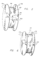
- Figure 2 is a perspective view of a support or take-up spool 26 for use in forming the sensing coil 10.
- the spool 26 includes a pair of generally- circular flanges 28 and 30 mounted to opposed ends of a cylindrical hollow core 32 to form boundaries for retaining turns of the optical fiber as the sensing coil 10 is wound thereon.
- An orthogonally wound layer 34 of nylon fiber, of uniform diameter and roundness, may be fixed (by gluing or like means) to the surface of the core 32.
- the diameter of such fiber is preferably at least as great as that of the optical fiber of the coil and should not exceed it by more than three (3) per cent to assure that an identical number of turns per layer is achieved in the winding of the coil upon the spool.
- the equivalent pattern may be formed by machining, molding or the like, at the surface of the core 32. It will become apparent from the discussion that follows that such texturing of the surface of the core promotes the winding of orthogonal layers onto the spool.
- the flanges 28, 30 may be either permanently or removably fixed to the core 32. In a detachable assembly, the flanges 28, 30 may be fixed by means of conventional spring-like metal fingers or the like that are arranged to engage the inner surface of the core 32.
- An exemplary embodiment of the spool 26 includes flanges of 15 centimeter diameters and 2.5 millimeter thickness with an outer core diameter of 14 centimeters and core thickness of 2.5 millimeters.
- the spool 26 is preferably of relatively high thermal conductivity and low thermal expansion coefficient material.
- Elongated apertures 36 and 38 are located in flanges 28 and 30 respectively. As will be shown below, such apertures provide a means for displacing the fiber supply segments beyond the flanges during the coil winding process to prevent undesired interferences with the coil formation process.
- the apertures 36, 38 extend from the surface of the core 32 to the flange's outer edges and are laterally displaced by a distance x. The significance of the relative displacements of the apertures 36, 38 will become apparent below.
- the apertures are not radial but rather separated by x throughout their lengths so that the size of a crossover region (discussed bleow) remains constant throughout the coil.
- Figure 3 is an partial broken front elevation view of a fiber optic sensing coil 10 wound upon a spool as illustrated in Figure 2.
- fiber of the supply segment 24 is displaced outside the flange 28 through the aperture 36.
- Fiber from supply segment 22, having "climbed" or risen from a preceding layer is wound orthogonally into the first turn of the next coil layer.
- the fiber material 12 is shown in exaggerated proportion with respect to flange thickness, the ratio of flange thickness to fiber diameter in an actual embodiment being approximately 10 to 1.
- each coil turn is oriented substantially perpendicular to the coil axis.
- a right angle 40 exists between the major portion 42 of each turn forming a layer and the coil axis 14.
- This alignment utilizes the grooves formed between adjacent turns (or an end turn that the adjacent flange) of adjacent coil layers to secure or anchor a substantial percentage of the length of each turn.
- Such grooves provide interlocking channels for guiding the turns of overlying layers.
- Such an interlocking effect can be seen quite clearly at the lower sectional portion of the coil of Figure 3.
- the substantially round fibers of adjacent layers are seen to fit neatly into the grooves that exist between the round fibers of the preceding layer.
- the number of turns of the optical fiber determines the distance d between the opposed interior surfaces of the flanges 28 and 30.
- the distance d is calculated as:
- each coil turn is orthogonal to the coil axis 14.
- a "cross-over" region of turn segments that are angularly-inclined with respect to the major orthogonal turn segments is formed in each layer.
- the angularly-inclined segments (each of which comprises between five to ten per cent of a coil turn depending on coil diameter) of overlying coil layers do not interlock as to the orthogonal turn segments. Rather, the design of the coil is effectively "anchored” throughout ninety (90) to ninety-five (95) percent of the windings so that both the beginning and the end of each angularly-inclined turn section is reliably secured. As a result, inconsistencies (in terms of angular orientations) between the crossover regions of overlying coil layers do not degrade the structure.
- a cutaway section for exposing a portion of the cross-over region of the underlying fiber layer the fibers of this region are oppositely directed.
- such a reversal can be sustained in Applicant's coil unlike a helically-wound coil wherein an anchoring orthogonal turn section is not provided.
- a cross-over region of the fiber layer is formed between taper point 46 and taper point 48 of the interior surfaces of the flanges 28 and 30 respectively that define the beginnings of tapers in the flanges towards the apertures 36 and 38.
- the tapers and the apertures provide room for the fiber to "climb" up and around the end turns of preceding layers without disturbing the layer.
- a bend 50 of the fiber occurs as the fiber of a supply segment climbs from the underlying layer formed from that supply segment.
- the geometry of the flange 30 is arranged so that its interior surfaces begin to taper at 48, 52 while the exterior surfaces of the flange 30 begin to taper at 54, 56 toward the rounded apexes 58, 60 that define the sides of the aperture 38.
- a like arrangement is provided with respect to the region of the aperture 36 of the flange 28.
- the exterior tapers of the flanges provide a measure of protection when the supply segments are displaced outside or within an aperture preventing undesirable "pinching" of the optical fiber.
- the rounded apexes provide further protection against damage to the fiber during the winding of the coil.
- FIG 4 a partially broken side elevation view taken at 4-4 of Figure 3.
- end turns each from a different coil layer adjacent the flange 30 are numbered sequentially from 62 to 78.
- Figure 4 relates to a coil of quadrupole symmetry wherein the end turns 62, 68, 70, 76, and 78 (i.e.
- every fourth layer, beginning with the layer adjacent the core of the spool) are wound from one supply segment while the layers of the turns 64, 66, 72, and 74 are wound from the other supply segment.
- the inclined section 80 of fiber of the first supply segment climbs around the edge turns (and layers aligned therewith) to reach and thereby initiate the formation of an overlying layer indicated by the end turn 68.
- an inclined section 82 begins with the end turn 70 that is shown to lie atop the layer 68 and climbs above the two layers of end turns 72 and 74 to begin the end turn 76 that initiates the corresponding overlying layer.
- the identical climbing process occurs at the opposed edge or "cheek" of the coil.
- the two sequences are staggered as a result of the occurrence of an initial one-layer step from the innermost layer to an overlying layer. Thereafter, the climbing or winding proceeds by the illustrated "jumping" of two overlying layers.
- the second supply segment climbs from layer 62 to layer 64, then from layer 66 to layer 72, etc.
- Figure 5 corresponds generally to the preceding figure for illustrating an orthogonally wound optical fiber having alternative dualpole symmetry.
- each adjacent layer is wound from a different supply segment alternating with every layer rather than with every other layer as in the coil of the quadrupole symmetry described above.
- this variation of the winding process is enhanced by a spool design that differs from the spool utilized for forming a quadrupole wound coil.
- inclined segments originating with each supply segment, extend from each end turn at each of the opposed cheeks of the coil.
- inclined segments 84 from the first supply climb from layers 86 to 90, 94 to 98, and 102 to 106 respectively while the oppositely inclined fiber segments 110 of the second supply climb from layers 88 to 92, 96 to 100 and 104 to 108 respectively.
- the turns of both quadrupole and dualpole wound coils are characterized by substantially larger orthogonal portions than the angular portions that comprise the cross-over regions of each layer.
- the major portion of each turn interlocks with those of underlying layers so that the beginnings and ends of crossover region segments are secured and their preferred orientations preserved.
- both embodiments avoid the harmful distortion of turns that occurs in the formation of a helically wound coil.
- FIG. 6 is a perspective view of a spool 112 adapted for use in forming a dualpole wound coil.
- flanges 114, 116 include elongated apertures separated by an identical distance x for permitting and assisting the above described fiber climbing process.
- a pair of apertures 118, 120 are formed in each of the flanges 114, 116 rather than a single opening.
- the additional aperture is provided to prevent interference between the oppositely-directed supplies during the winding process.
- the positions of the oppositely-inclined "climbing" portions of turns are separated preventing undesirable crossing of the inclined segments 84 and 110 of Figure 5.
- the fiber is wound from two supplies onto the spool.
- one supply is clamped coaxially to the spool and rotated therewith to wind one or more layers from the other supply.
- a shuttle is used to guide the fiber on the desired path.
- the one supply is released and the other clamped coaxially to the spool so that one or more layers can be wound from the one supply.
- This process is repeated, alternating between the supplies, until all the layers are complete and an orthocyclic winding is achieved.
- the center of the fiber will lie at the centre of the innermost layer. It thus follows that the supply used to form the innermost layer will have supplied one half a layer more than the other supply. It is also a result that, commencing from the center of the fiber, the two paths to the free ends are substantially symmetrical, this resulting from the use of two supplies for the one fiber.
Landscapes
- Physics & Mathematics (AREA)
- Optics & Photonics (AREA)
- Engineering & Computer Science (AREA)
- General Physics & Mathematics (AREA)
- Electromagnetism (AREA)
- Power Engineering (AREA)
- Radar, Positioning & Navigation (AREA)
- Remote Sensing (AREA)
- Light Guides In General And Applications Therefor (AREA)
- Gyroscopes (AREA)
Claims (16)
Applications Claiming Priority (2)
| Application Number | Priority Date | Filing Date | Title |
|---|---|---|---|
| US07/030,593 US4793708A (en) | 1987-03-27 | 1987-03-27 | Fiber optic sensing coil |
| US30593 | 1987-03-27 |
Publications (3)
| Publication Number | Publication Date |
|---|---|
| EP0292103A2 EP0292103A2 (fr) | 1988-11-23 |
| EP0292103A3 EP0292103A3 (en) | 1989-04-05 |
| EP0292103B1 true EP0292103B1 (fr) | 1991-02-06 |
Family
ID=21854958
Family Applications (1)
| Application Number | Title | Priority Date | Filing Date |
|---|---|---|---|
| EP88302679A Expired - Lifetime EP0292103B1 (fr) | 1987-03-27 | 1988-03-25 | Bobine de mesure à fibre optique |
Country Status (5)
| Country | Link |
|---|---|
| US (1) | US4793708A (fr) |
| EP (1) | EP0292103B1 (fr) |
| JP (1) | JPS646720A (fr) |
| CA (1) | CA1289230C (fr) |
| DE (1) | DE3861744D1 (fr) |
Families Citing this family (40)
| Publication number | Priority date | Publication date | Assignee | Title |
|---|---|---|---|---|
| US4883337A (en) * | 1988-08-29 | 1989-11-28 | The Charles Stark Draper Laboratory, Inc. | Low strain optical fiber coil |
| US5072965A (en) * | 1989-05-31 | 1991-12-17 | Mitsubishi Denki K.K. | Suspension control device |
| JP2908496B2 (ja) * | 1990-02-14 | 1999-06-21 | 株式会社デンソー | ショックアブソーバの減衰力制御装置 |
| DE69212650T2 (de) * | 1991-11-25 | 1997-01-16 | Honeywell Inc | Glasfaserwicklung |
| US5506923A (en) * | 1991-11-25 | 1996-04-09 | Honeywell Inc. | Apparatus and method for trimming of fiber optic winding |
| RU94027291A (ru) * | 1991-11-25 | 1996-06-20 | Ханивелл Инк. (Us) | Волоконнооптическая катушка, способ ее намотки и многослойная катушка |
| EP0651876B1 (fr) * | 1992-07-21 | 1998-04-22 | Honeywell Inc. | Ajustage d'un enroulement de fibres optiques |
| US5371593A (en) * | 1992-08-31 | 1994-12-06 | Litton Systems, Inc. | Sensor coil for low bias fiber optic gyroscope |
| US5351900A (en) * | 1992-10-21 | 1994-10-04 | Optelecom, Inc. | Method of manufacture of quadrupole-wound fiber optic sensing coil |
| DE4301480C1 (de) * | 1993-01-21 | 1994-05-26 | Deutsche Aerospace | Verfahren und Vorrichtung zum Wickeln von Faserspulen für optische Faserkreisel |
| US5333214A (en) * | 1993-02-12 | 1994-07-26 | Litton Systems, Inc. | Apparatus for reducing magnetic field-induced bias errors in a fiber optic gyroscope |
| JPH078806U (ja) * | 1993-07-08 | 1995-02-07 | 日本航空電子工業株式会社 | 光ファイバコイル |
| EP0641996A1 (fr) * | 1993-09-03 | 1995-03-08 | Litton Systems, Inc. | Bobine captrice d'un gyroscope à fibre optique |
| US5841932A (en) * | 1996-06-21 | 1998-11-24 | Honeywell Inc. | Optical fiber coil and method of winding |
| US5405485A (en) * | 1994-01-14 | 1995-04-11 | Litton Systems, Inc. | Robotic fiber optic quadrupole coil winder |
| US5778016A (en) | 1994-04-01 | 1998-07-07 | Imra America, Inc. | Scanning temporal ultrafast delay methods and apparatuses therefor |
| US5545892A (en) * | 1994-09-01 | 1996-08-13 | Litton Systems, Inc. | Gyro sensor coil with low-friction hub interface |
| US5486922A (en) * | 1994-12-20 | 1996-01-23 | Litton Systems, Inc. | Sensor coil with thermomechanically-matched spool for fiber optic gyroscope |
| US5657411A (en) * | 1995-12-15 | 1997-08-12 | Honeywell Inc. | Negative trimming of fiber optic winding |
| US5767509A (en) * | 1996-12-24 | 1998-06-16 | Litton Systems, Inc. | Fiber optic sensor coil including buffer regions |
| JPH10206675A (ja) * | 1997-01-24 | 1998-08-07 | Ngk Insulators Ltd | ファイバコイル用リール |
| US5781301A (en) * | 1997-03-31 | 1998-07-14 | The United States Of America As Represented By The Secretary Of The Army | Thermally symmetric, crossover-free fiber optic sensor coils and method for winding them |
| US5870194A (en) * | 1997-08-01 | 1999-02-09 | Litton Systems, Inc. | Gyro sensor coil with filled optical fiber |
| US20020003936A1 (en) * | 1998-10-19 | 2002-01-10 | Andrew W. Kaliszek | Fine spaced winding pattern for fiber optic coil |
| US6005665A (en) * | 1998-12-29 | 1999-12-21 | Honeywell, Inc. | Job zone for a high performance navigation grade rate sensing coil |
| US6215933B1 (en) | 1999-07-15 | 2001-04-10 | Litton Systems, Inc. | Bifilar fog coil winding pattern with improved shupe bias canceling properties |
| US6883744B2 (en) | 2001-11-19 | 2005-04-26 | Sonoco Development, Inc. | Spool for optical fiber media |
| US6663876B2 (en) | 2002-04-29 | 2003-12-16 | Piedmont Pharmaceuticals, Llc | Methods and compositions for treating ectoparasite infestation |
| US7237746B2 (en) * | 2003-12-08 | 2007-07-03 | Sonoco Development, Inc. | Spool having reversing spiral guide |
| US7713196B2 (en) | 2007-03-09 | 2010-05-11 | Nellcor Puritan Bennett Llc | Method for evaluating skin hydration and fluid compartmentalization |
| US8560059B2 (en) * | 2007-03-09 | 2013-10-15 | Covidien Lp | System and methods for optical sensing and drug delivery using microneedles |
| US7903255B2 (en) * | 2007-08-16 | 2011-03-08 | Celight, Inc. | Sagnac sensor with nested waveguides |
| US7626762B2 (en) * | 2007-11-13 | 2009-12-01 | Honeywell International Inc. | Jog zone free fiber optic coil |
| CN101551249B (zh) * | 2008-11-19 | 2011-04-27 | 北京航天时代光电科技有限公司 | 一种可分离式骨架及利用该骨架实现的光纤线圈制备方法 |
| US8958074B1 (en) | 2012-08-27 | 2015-02-17 | The Boeing Company | Low strain optical fiber coil and associated fiber optic gyroscope and method |
| CN105158864A (zh) * | 2015-09-10 | 2015-12-16 | 国家电网公司 | 一种保护光纤尾纤的安全支架 |
| US11047688B2 (en) | 2017-10-13 | 2021-06-29 | Northrop Grumman Systems Corporation | Flange-bonded loopback for fiber-optic gyroscope (FOG) |
| US11079230B2 (en) | 2019-05-10 | 2021-08-03 | Northrop Grumman Systems Corporation | Fiber-optic gyroscope (FOG) assembly |
| CN110824643A (zh) * | 2019-11-21 | 2020-02-21 | 中国船舶重工集团公司第七0五研究所 | 一种全海深光纤线团 |
| CN116885536B (zh) * | 2023-07-03 | 2024-05-07 | 广州芯朋科技有限公司 | 一种光纤放大器的盘纤组件 |
Citations (1)
| Publication number | Priority date | Publication date | Assignee | Title |
|---|---|---|---|---|
| US4410275A (en) * | 1981-03-31 | 1983-10-18 | The Board Of Trustees Of The Leland Stanford Junior University | Fiber optic rotation sensor |
Family Cites Families (7)
| Publication number | Priority date | Publication date | Assignee | Title |
|---|---|---|---|---|
| US3635421A (en) * | 1969-11-20 | 1972-01-18 | Western Electric Co | Spool assemblies |
| DE3101126A1 (de) * | 1981-01-15 | 1982-07-29 | Leopold 6831 Reilingen Weinlich | "verfahren zum aufwickeln von fadenfoermigem wickelgut, insbesondere kabeln" |
| IL65344A (en) * | 1981-03-31 | 1987-08-31 | Univ Leland Stanford Junior | Single continuous optical fiber rotation sensor |
| CA1160611A (fr) * | 1981-06-15 | 1984-01-17 | Masamichi Yataki | Bobine reglable |
| US4408882A (en) * | 1981-07-02 | 1983-10-11 | The United States Of America As Represented By The Secretary Of The Navy | Optical gyroscope with time dependent wavelength |
| DE3332718C2 (de) * | 1983-09-10 | 1994-12-22 | Sel Alcatel Ag | Einrichtung zur Messung der Drehgeschwindigkeit |
| FR2583872B1 (fr) * | 1985-06-21 | 1987-08-07 | Thomson Csf | Procede de bobinage d'un gyroscope a fibre optique et bobine de fibre optique ainsi obtenue. |
-
1987
- 1987-03-27 US US07/030,593 patent/US4793708A/en not_active Expired - Fee Related
-
1988
- 1988-03-25 DE DE8888302679T patent/DE3861744D1/de not_active Expired - Fee Related
- 1988-03-25 CA CA000562538A patent/CA1289230C/fr not_active Expired - Fee Related
- 1988-03-25 JP JP63069895A patent/JPS646720A/ja active Pending
- 1988-03-25 EP EP88302679A patent/EP0292103B1/fr not_active Expired - Lifetime
Patent Citations (1)
| Publication number | Priority date | Publication date | Assignee | Title |
|---|---|---|---|---|
| US4410275A (en) * | 1981-03-31 | 1983-10-18 | The Board Of Trustees Of The Leland Stanford Junior University | Fiber optic rotation sensor |
Also Published As
| Publication number | Publication date |
|---|---|
| EP0292103A3 (en) | 1989-04-05 |
| US4793708A (en) | 1988-12-27 |
| DE3861744D1 (de) | 1991-03-14 |
| CA1289230C (fr) | 1991-09-17 |
| JPS646720A (en) | 1989-01-11 |
| EP0292103A2 (fr) | 1988-11-23 |
Similar Documents
| Publication | Publication Date | Title |
|---|---|---|
| EP0292103B1 (fr) | Bobine de mesure à fibre optique | |
| US4856900A (en) | Quadrupole-wound fiber optic sensing coil and method of manufacture thereof | |
| JPH0612261B2 (ja) | 光フアイバジヤイロスコ−プのコイル形成方法及び該方法によつて形成される光フアイバコイル | |
| JP3365285B2 (ja) | Szスロット型光ファイバケーブルの製造方法及び装置 | |
| US4688888A (en) | Optical cable | |
| US5279474A (en) | Mandrel for high density filament winding | |
| US4826279A (en) | Optical fiber unit | |
| US7090162B2 (en) | Apparatus and method of winding optical fiber sensor coil for fiber optic gyroscope | |
| GB2040063A (en) | A fibre optic cable and its method of manufacture | |
| US7168646B2 (en) | Trapezoidal coil for fiber optic gyroscopes | |
| JPH05134126A (ja) | 光ケーブル及び/又は光ケーブルコアを接続する継手 | |
| PL117868B1 (en) | Deflector coil for tv receivers | |
| US5154366A (en) | High density filament winding and method for producing improved crossovers and inside payout | |
| US5221060A (en) | Thermal expansion compensated winding of optical fiber canisters | |
| US4925125A (en) | Deep nested filament winding | |
| EP0396735B1 (fr) | Enroulement de filament de haute densite et procede de production de croisements et de deroulement interieur ameliores | |
| EP0396705B1 (fr) | Appareil et procede permettant d'enrouler des materiaux filiformes, tels que des fibres optiques, en bobines plates | |
| KR100657187B1 (ko) | 광 케이블 | |
| EP0321578B1 (fr) | Element d'ecartement et de support de fibres optiques | |
| EP0825465B1 (fr) | Câble électrique monocoeur avec un élément à fibre optique | |
| CA1333130C (fr) | Enroulement filamentaire tres dense et methode servant a produire des croisements ameliores et a permettre le devidage par l'interieur | |
| US6215933B1 (en) | Bifilar fog coil winding pattern with improved shupe bias canceling properties | |
| JPH03142405A (ja) | 余分な長さの光学的リードを収容する装置 | |
| CA1315139C (fr) | Separateur a fibres optiques | |
| GB1595664A (en) | Reel of tape for winding on cable |
Legal Events
| Date | Code | Title | Description |
|---|---|---|---|
| PUAI | Public reference made under article 153(3) epc to a published international application that has entered the european phase |
Free format text: ORIGINAL CODE: 0009012 |
|
| AK | Designated contracting states |
Kind code of ref document: A2 Designated state(s): DE FR GB |
|
| PUAL | Search report despatched |
Free format text: ORIGINAL CODE: 0009013 |
|
| AK | Designated contracting states |
Kind code of ref document: A3 Designated state(s): DE FR GB |
|
| 17P | Request for examination filed |
Effective date: 19890906 |
|
| 17Q | First examination report despatched |
Effective date: 19890126 |
|
| GRAA | (expected) grant |
Free format text: ORIGINAL CODE: 0009210 |
|
| AK | Designated contracting states |
Kind code of ref document: B1 Designated state(s): DE FR GB |
|
| REF | Corresponds to: |
Ref document number: 3861744 Country of ref document: DE Date of ref document: 19910314 |
|
| ET | Fr: translation filed | ||
| PLBE | No opposition filed within time limit |
Free format text: ORIGINAL CODE: 0009261 |
|
| STAA | Information on the status of an ep patent application or granted ep patent |
Free format text: STATUS: NO OPPOSITION FILED WITHIN TIME LIMIT |
|
| PGFP | Annual fee paid to national office [announced via postgrant information from national office to epo] |
Ref country code: FR Payment date: 19911211 Year of fee payment: 5 |
|
| PGFP | Annual fee paid to national office [announced via postgrant information from national office to epo] |
Ref country code: GB Payment date: 19911225 Year of fee payment: 5 |
|
| 26N | No opposition filed | ||
| PGFP | Annual fee paid to national office [announced via postgrant information from national office to epo] |
Ref country code: DE Payment date: 19920331 Year of fee payment: 5 |
|
| PG25 | Lapsed in a contracting state [announced via postgrant information from national office to epo] |
Ref country code: GB Effective date: 19930325 |
|
| GBPC | Gb: european patent ceased through non-payment of renewal fee |
Effective date: 19930325 |
|
| PG25 | Lapsed in a contracting state [announced via postgrant information from national office to epo] |
Ref country code: FR Effective date: 19931130 |
|
| PG25 | Lapsed in a contracting state [announced via postgrant information from national office to epo] |
Ref country code: DE Effective date: 19931201 |
|
| REG | Reference to a national code |
Ref country code: FR Ref legal event code: ST |