EP0291654B1 - Hydraulic door opening or closing device - Google Patents
Hydraulic door opening or closing device Download PDFInfo
- Publication number
- EP0291654B1 EP0291654B1 EP88103891A EP88103891A EP0291654B1 EP 0291654 B1 EP0291654 B1 EP 0291654B1 EP 88103891 A EP88103891 A EP 88103891A EP 88103891 A EP88103891 A EP 88103891A EP 0291654 B1 EP0291654 B1 EP 0291654B1
- Authority
- EP
- European Patent Office
- Prior art keywords
- ports
- cylinder
- piston
- sets
- valved
- Prior art date
- Legal status (The legal status is an assumption and is not a legal conclusion. Google has not performed a legal analysis and makes no representation as to the accuracy of the status listed.)
- Expired - Lifetime
Links
- 239000012530 fluid Substances 0.000 claims abstract description 83
- 238000004891 communication Methods 0.000 claims abstract description 3
- 230000002441 reversible effect Effects 0.000 claims description 17
- 230000033001 locomotion Effects 0.000 claims description 9
- 230000001105 regulatory effect Effects 0.000 claims description 3
- 230000009977 dual effect Effects 0.000 abstract description 3
- 101100411643 Saccharomyces cerevisiae (strain ATCC 204508 / S288c) RAD5 gene Proteins 0.000 description 4
- 239000003990 capacitor Substances 0.000 description 3
- 230000008859 change Effects 0.000 description 3
- 238000004519 manufacturing process Methods 0.000 description 3
- 230000009467 reduction Effects 0.000 description 3
- 230000009471 action Effects 0.000 description 2
- 238000010276 construction Methods 0.000 description 2
- 230000026058 directional locomotion Effects 0.000 description 2
- 230000000694 effects Effects 0.000 description 2
- 238000009434 installation Methods 0.000 description 2
- 239000007788 liquid Substances 0.000 description 2
- 238000012423 maintenance Methods 0.000 description 2
- 230000002028 premature Effects 0.000 description 2
- 230000004043 responsiveness Effects 0.000 description 2
- 238000007789 sealing Methods 0.000 description 2
- 230000001133 acceleration Effects 0.000 description 1
- 230000003213 activating effect Effects 0.000 description 1
- 230000001276 controlling effect Effects 0.000 description 1
- 230000001351 cycling effect Effects 0.000 description 1
- 230000003247 decreasing effect Effects 0.000 description 1
- 238000001514 detection method Methods 0.000 description 1
- 238000010586 diagram Methods 0.000 description 1
- 238000007667 floating Methods 0.000 description 1
- 230000006870 function Effects 0.000 description 1
- 238000003780 insertion Methods 0.000 description 1
- 230000037431 insertion Effects 0.000 description 1
- 239000000463 material Substances 0.000 description 1
- 230000007246 mechanism Effects 0.000 description 1
- 238000007665 sagging Methods 0.000 description 1
- 230000011664 signaling Effects 0.000 description 1
- 230000000153 supplemental effect Effects 0.000 description 1
- 230000001360 synchronised effect Effects 0.000 description 1
- 238000004804 winding Methods 0.000 description 1
Images





Classifications
-
- B—PERFORMING OPERATIONS; TRANSPORTING
- B66—HOISTING; LIFTING; HAULING
- B66B—ELEVATORS; ESCALATORS OR MOVING WALKWAYS
- B66B13/00—Doors, gates, or other apparatus controlling access to, or exit from, cages or lift well landings
-
- B—PERFORMING OPERATIONS; TRANSPORTING
- B66—HOISTING; LIFTING; HAULING
- B66B—ELEVATORS; ESCALATORS OR MOVING WALKWAYS
- B66B13/00—Doors, gates, or other apparatus controlling access to, or exit from, cages or lift well landings
- B66B13/02—Door or gate operation
- B66B13/06—Door or gate operation of sliding doors
- B66B13/08—Door or gate operation of sliding doors guided for horizontal movement
-
- E—FIXED CONSTRUCTIONS
- E05—LOCKS; KEYS; WINDOW OR DOOR FITTINGS; SAFES
- E05F—DEVICES FOR MOVING WINGS INTO OPEN OR CLOSED POSITION; CHECKS FOR WINGS; WING FITTINGS NOT OTHERWISE PROVIDED FOR, CONCERNED WITH THE FUNCTIONING OF THE WING
- E05F15/00—Power-operated mechanisms for wings
- E05F15/50—Power-operated mechanisms for wings using fluid-pressure actuators
- E05F15/56—Power-operated mechanisms for wings using fluid-pressure actuators for horizontally-sliding wings
-
- E—FIXED CONSTRUCTIONS
- E05—LOCKS; KEYS; WINDOW OR DOOR FITTINGS; SAFES
- E05Y—INDEXING SCHEME ASSOCIATED WITH SUBCLASSES E05D AND E05F, RELATING TO CONSTRUCTION ELEMENTS, ELECTRIC CONTROL, POWER SUPPLY, POWER SIGNAL OR TRANSMISSION, USER INTERFACES, MOUNTING OR COUPLING, DETAILS, ACCESSORIES, AUXILIARY OPERATIONS NOT OTHERWISE PROVIDED FOR, APPLICATION THEREOF
- E05Y2900/00—Application of doors, windows, wings or fittings thereof
- E05Y2900/10—Application of doors, windows, wings or fittings thereof for buildings or parts thereof
- E05Y2900/104—Application of doors, windows, wings or fittings thereof for buildings or parts thereof for elevators
Definitions
- the invention relates to a door opening and closing device to be operated by fluid pressure, comprising:
- the invention relates to the field of designing closure apparatus for overhead sliding doors and, more particularly, to a hydraulic door opening or closing device.
- a hydraulic fluid-filled cylinder could be sequentially emptied and filled so as to drive a door opening and closure.
- a valved cylinder drives a piston by fluid pressure and a dash pot retards the final closing of the door.
- power door openers using single speed AC motors provide a constant opening and closing speed checked and slowed by air or oil checks.
- the air and oil check speed control arrangements must be particularly adjusted and often require supplemental control arrangements.
- AC motor systems are complicated to construct and comprise a large number parts. Many of these parts are susceptible to wear and require frequent maintenance.
- the invention provides a door opening and closing device of the type mentioned in the beginning, which is characterized in that said closed wall portion of said cylinder extending for at least the predetermined length of the head portion of said piston, so that said head portion successively covers and uncovers all of said ports of said sets of ports when moving from one end to the other end of said cylinder, and vice versa; and said ports of said sets of ports are designed such that by far the majority of the hydraulic fluid transmitted via one of said passages is being by-passed through the cylinder directly back to the pump via the other end of said passages when the piston head is near the end of its respective travel distance.
- each of said valves has a head seated in a bore and threadably engages with a manifold comprising one of said sets of ports and one of said valved ports positioned adjacent thereto, said head having a stem projecting therefrom and including a tapered end adjacent to said valved port, so that a rotation of said head causes said tapered end to move with respect to the valved port, thereby variably restricting or regulating the passage of fluid through said valved port.
- the invention provides a door opening and closing device of the type mentioned in the beginning, which is characterized in that the ports of said two sets of ports are valved ports, each provided with a check valve and each of said sets of ports being by-passed by a respective branch line which contains a directional valve and opens into the respective end of said cylinder.
- a preferred embodiment of this device according to the second aspect of the invention is characterized in that said closed wall portion of said cylinder extending for at least the predetermined length of the head portion of said piston, so that said head portion successively covers and uncovers all of said ports of said sets of ports when moving from one end to the other end of said cylinder, and vice versa; and said ports of said sets of ports are designed such that by far the majority of the hydraulic fluid transmitted via one of said pump ports being by-passed through the cylinder directly back to the pump via that passage associated with the other of said pump ports when the piston head is near the end of its respective travel distance.
- each of said valves comprises a setting screw and a ball, the setting screw having a longitudinal extension limiting the upward movement of the ball and, consequently, the degree of fluid flow through each port.
- the present arrangement comprises an inherent door speed control arrangement without any requirement for additional speed control-related circuits or systems.
- the device can be coupled to a control circuit providing three modes of door operation: door opening, door closing and door reversing, in particular, from closing to opening operation.
- the present control circuit is not concerned with speed control. Consequently, the associated circuitry is simplified and, in particular, can be constructed in plug-in modular circuit board form.
- the control circuit comprises a pair of micro-switches signaling a fully extended or fully retracted position of the piston rod and a plurality of plug-in relays activating a reversible rotation of the hydraulic fluid pump depending on the mode of door operation.
- the control system can include a timer for shutting down the pump motor in the event door travel is restricted by mechanical means for an unduly long period.
- FIG.'s 1 to 11B similar elements have been identified with the same reference numerals or characters wherever possible.
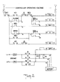
- the hydraulic door opening or closing device of the present invention is particularly shown in FIG.'s 1 and 3 to 11B, while a control circuit for the hydraulic door opening or closing device is shown in FIG. 2.
- FIG. 1 there is shown a front view of an elevator car 1 having sliding doors 2, 3 which close in the center of the car hung on a track 4.
- Pulleys 5, 6 are arranged on each side of the top of the elevator car 1 such that a left-hand door 2 is drawn to the left upon track while a right hand door 3 is drawn to the right upon opening.
- the doors are hung from track 4 and guided along the track by upper and lower roller sets.
- Some elevator car sliding doors comprise two pairs of doors opening from one side to the other.
- the door that must travel the farthest to open is typically geared so that it travels twice as fast as the other.
- Such an arrangement is not shown in the drawings nor are other arrangements well known in the art. However, all such arrangements may be easily adapted for application of the present device and the center sliding door arrangement shown is merely exemplary of such arrangements.
- the present hydraulic door opening or closing device is equally suited to application in any door system such as those installed in train cars or as warehouse doors.
- the hydraulic door opening or closing device comprises a rotary gear pump motor 7 having two ports which, responsive to a change in power feed, pumps in reverse direction. That is, at one point in time, hydraulic fluid line 12 connected to one port may be a pressure line while fluid line 11 connected to the other port will be a suction line and, upon a change in power feed, fluid line 11 becomes a pressure line and line 12 becomes a suction line.
- Hy Pack (div. of WEAVER Corp.) which may be driven by a Franklin Electric Model 1903180400 PR1, a 220 volt, single phase motor rated at 425 watts with a full load.
- This Franklin Electric motor requires a run capacitor C1 of approximately fifteen microfarads.
- Resistor R1 (15,000 ohm, zwatt) is installed across the terminals of capacitor C1 to bleed charge from the capacitor reducing arcing of the contacts during rapid cycling.
- Fluid line 11 couples pump motor 7 to a first manifold 8 which drives a piston 14 inside cylinder or barrel 10 to close doors 2 and 3 via rod 13.
- Rod 13 is attached in a well known manner to the doors 2 or 3 and is most conveniently in a line approximately parallel to the line of directional door movement represented, for example, by the track 4.
- the pump motor 7 and its connection to the barrel 10 should be arranged so that the fluid lines 11, 12 are as short as possible.
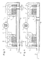
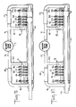
- FIG. 2 there is shown a control circuit for the hydraulic door opening or closing device shown in FIG. 1 which will be further explained by aid of FIGs. 3 to 10 showing the hydraulic door opening or closing device in operation.
- the control circuit of FIG. 2 is connected via fuses F1 and F2 and terminals L1, L2 to a controlled operating voltage that is chosen appropriately for operating parallel-connected relays XC, C, REV, 0, and XO which, in turn are connected in series via relay DPT with one power feed line to the pump motor 7.
- Power for pump motor 7 is provided via fuses F3 and F4 and 220 VAC single phase line terminals L11 and L12. As will be subsequently explained, a reversal of pump motor 7 is accomplished by an alternate feeding of power via terminal M14 or terminal M15 of motor 7 while terminal M13 of motor 7 is always coupled to line terminal L12.
- relays employed in the practice of this invention may be KU Series, Plug-in type relays available from Potter & Brumfield.
- Microswitches DOL an DCL are mounted in relationship to rod 13 such that switch DOL identifies a fully retracted or door open position while switch DCL identifies a fully extended or door closed position.
- An example of a commercially available microswitch useful in the practice of this invention is Burgess At. No. CT2KR2-A2.
- Timer circuit T1 e.g., Potter & Brumfield Type CB
- relay DPT e.g., Potter & Brumfield Type CB
- the control circuit of FIG. 2 may be most conveniently implemented in the form of a single printed circuit board equipped with plug-in relays, fuses, microswitch contacts and other components, greatly reducing the amount of separate components required by the present invention.
- control circuit shown in FIG. 2 provides three modes of operation of the hydraulic door opening or closing device of FIG. 1: a door opening mode, a door closing mode and a door reversing mode such that upon certain conditions, a door closing is reversed to a door opening operation.
- a door opening mode a door opening mode
- a door closing mode a door closing mode
- a door reversing mode such that upon certain conditions, a door closing is reversed to a door opening operation.
- rotary gear pump 7 coupled to first and second manifolds 8 and 9 via hydraulic fluid lines 11 and 12 respectively, cylinder or barrel 10 and rod 13 as shown in FIG. 1.
- rod 13 is coupled to a piston head 14 driven within barrel 10 by fluid pressure.
- Fluid lines 11 and 12 each branch into two branch lines.
- Branch lines 15 and 16 are connected to opposite ends of barrel 10 via two directional flow valves 17 and 18 respectively.
- the other branch lines 19 and 20 each run to a plurality of ball valves linearly spaced along each end of barrel 10.
- First manifold 8 comprises five such ball valves 21 to 25 and second manifold 9 also comprises five such ball valves 26 to 30.
- Each such ball valve is fluidly coupled between an associated branch line and the barrel 10 via a ball such that in a down position an opening to barrel 10 is closed and in an up position fluid flow is permitted between barrel 10 and an associated branch line in accordance with a screw adjustment as will be more particularly described in a discussion of FIGs. 11A and 11B.
- branch line 19 parallels barrel 10 in the vicinity of ball check valves 21 to 25.
- these ball check valves 21 to 25 provide a fluid bypass to a flow of fluid via branch line 15.
- ball check valves 26-30 provide a fluid bypass to a flow of fluid via branch line 16.
- Useful flow control check valves are commercially available, e.g., Detroit Fluid Products part no. EC10B.
- a command signal to close the elevator doors is generated from a main elevator control panel, typically in an elevator machine room (not shown).
- the command signal is transmitted to the control circuit of FIG. 2 via control signal terminal CS.
- the receipt of the control signal at terminal CS closes the contacts CLOSE between terminals COM 1 and CS3. This is accomplished, for example, by relay actuation.
- terminal CS The contacts CLOSE of terminal CS being closed, an electrical path is formed via terminal L1, fuse F1, closed contacts DPT2 and DPT10, normally closed contacts O2 and O10, and normally closed contacts REV2 and REV10 to the parallel connection of hold closed relay XC with close relay C via normally closed door close limit switch DCL contacts DCL6 and DCL7.
- close relay C is actuated via the normally closed contacts DCL6, DCL7 of door close limit switch DCL.
- Normally open close relay contacts C5, C9 now close a path providing power via terminal L11 and terminal M14 to pump motor 7 and via close relay contacts C8, C12 to power terminal L12.
- the power connection of motor terminals M14, M13 ensures that the pump motor 7 runs in such a direction as to close the elevator doors.
- the applied voltage from line 12 is connected to the line side of delay time T1. If either of the O or C relays are energized longer than the time constant value for TI then the DPT relay is energized.
- the rotary gear pump 7 establishes a pressure in fluid line 11 and a suction in fluid line 12. Fluid is at first pumped through directional flow control valve 17 into the barrel 10 by way of branch line 15.
- the piston 14 and rod 13 have traveled outward at a constant velocity driven by the continuous operation of pump motor 7.
- the pressurized side of piston seal 14 passes the first opening in the wall of the barrel 10 to the first ball check valve 26, the velocity of the piston 14 and rod 13 reduces.
- This reduction in piston velocity relates to a reduction in pressure on the drive side of piston 14 caused by a portion of the hydraulic fluid under pressure being by-passed directly back to the pump motor 7 via branch line 20 and fluid line 12.
- a further decrease in piston velocity follows as the piston 14 passes each ball check valve 26 to 29.
- the second manifold 9 automatically converts to a bypassing operation from a completely directional operation providing an inherent speed control.
- valves 26 to 29 are all bypassing fluid back to pump motor 7 and only ball valve 30 is releasing fluid pressure on the driven side of the piston 14. With this slow release of fluid through ball valve 30 there is a correspondingly slow directional movement of piston 14. Consequently, by far the majority of the hydraulic fluid transmitted via line 11 is being bypassed through the reservoir formed in the barrel 10 directly back to the pump motor 7 when the piston 14 is near the end of its travel distance.
- the door close limit switch DCL is mechanically actuated. Normally closed contacts DCL6, DCL7 open at this time de-energizing close relay C. This de-energization of close relay C results in the opening of close relay contacts C5, C9, C8, C12 turning power off to pump motor 7.
- relay XC provides a latching memory circuit which safeguards against opening, for example, passengers pulling the car door open while the elevator is in motion or a condition known as door sag, an unintentional, premature opening (or closing) of the doors.
- the door close microswitch contacts DCL6 and DCL7 return to their normally closed position energizing close relay C and turning power back on feeding pump motor 7 via motor terminals M13 and M14. In this manner, the correct, closed door position is maintained until a command to open is transmitted to control signal terminal CS.
- a command signal to open the elevator door is transmitted to control signal terminal CS from the main elevator controller.
- open contacts OPEN are closed and a path is established by line terminal L1 through normally closed switch DOL energizing open relay 0.
- hold open relay XO is energized holding open relay O and hold open relay XO energized. This holding open is caused by way of the closure of normally open hold open relay contacts XO5 and XO9.
- the several ball check valves 26 to 30 in the second manifold 9 are forced into their closed or down position. In particular, this is accomplished by the effects of the pump motor pressure applied to the surface area of the balls of the ball check valves 26 to 30 on the manifold side of the balls as compared with the reduced pressure effects on the surface area of the barrel side of the balls via the small holes in the barrel wall.
- the piston 14 and rod 13 continue to retract at a relatively constant velocity.
- the pressurized side of the piston passes the first ball check valve 21 of the first manifold 8, a portion of the pressurized fluid can bypass via open ball check valve 21 and branch line 19 directly to rotary gear pump 7. Consequently, there is a reduction in the velocity of piston 14.
- set screws of ball check valves 21 to 25 may be preset at the location of manufacture of the present device to establish a particular deceleration of piston 14 for the door opening operation. Eventually, the piston reaches its limit actuating the door open limit switch DOL.
- door open limit switch DOL has normally closed contacts DOL5, DOL9 which open at this time. This contact opening deenergizes open relay O turning off the pump motor 7.
- Hold open relay XO does not deenergize at this time as a hold open path is preserved through normally closed close relay contacts C2, C10.
- the hold open path including hold open relay XO creates a path to normally closed switch DOL such that in the event door open limit switch contacts DOL5, DOL9 are re-closed, the open relay O is automatically energized reopening the door. Consequently, hold open relay XO provides a safeguard against a door sagging, that is, a premature door closing caused by door closing spring action or an intentional passenger intervention.
- the pump motor 7 continuously runs generating a pressure in line 12 to reopen the door no matter what position the piston was in during its closing cycle, that is, as shown in FIGS. 3-6, at the time the reversal command signal is received.
- the hold open relay XO maintains the doors in an open position until a command signal to close is transmitted to command signal terminal CS.
- protection timing circuit comprising delay timer T1 and protection relay DPT.
- the purpose of the protection timing circuit is to turn off the pump motor 7 in the event that door travel is restricted by, for example, obstructions in the sliding door sill, the doors being knocked off track 4 or other obstructions.
- Delay timer T1 is connected on one side to motor terminal M13 and on the other side to protection relay DPT.
- protection relay DPT comprises normally closed contacts DPT2, DPT10 which are wired in series between the line voltage applied at terminal L1 and the controller circuit.
- the time constant of delay timer T1 is established at the predetermined travel time for one door cycle, either opening or closing.
- the delay timer T1 is energized and, at the same time, protection relay DPT is energized.
- the energization of relay DPT in turn causes normally closed protection relay contacts DP2, DP10 to open. Consequently, the entire controller is deenergized. Power is turned off to pump motor 7 due to the deenergized open relay O or close relay C.
- the controller circuit may be reactuated by turning the emergency stop switch (located within the elevator cabin) to OFF (not shown). This would automatically return protection relay contacts DPT2, DPT10 to their normally closed position. When such a emergency stop switch is returned to a RUN position, the controller circuit is already initialized and prepared to receive a door open, door close, or door reverse signal at terminal CS.
- the device shown in FIG. 11A is assembled from a barrel 10 into which is inserted a piston 14 and rod 13.
- Piston 14 is provided before its insertion with first and second O ring seals not particularly shown.
- annular grooves 31,32 are shown for seating the pair of O rings.
- An end cap 33 seals the barrel 10 at one end while, at the same time, provides an opening to fluid branch line 15.
- the end cap 33 is sealed inside the barrel 10 by an O-ring which is seated in annular groove 34 of the end cap.
- End cap 33 is also provided with an annular recessed shoulder 35 at its open end to the barrel 10. The recess of the shoulder 35 permits hydraulic fluid to flow to the final ball check valve 25 while at the same time is a stop for the full retraction of the rod 13.
- These O rings are the only parts susceptible to wear and, hence, replacement in the present hydraulic device.
- a similar end cap is provided at the other end of the barrel 10 but additionally comprises a third opening which is fluidly sealed about the rod 13. It also is sealed with the barrel 10, by an O ring and comprises a shoulder similar to shoulder 35.
- each manifold comprises two blocks, an upper ball check valve containing block 36 and a lower clamping block 37. These are clamped together by bolts or other fastening devices about barrel 10.
- branch fluid line 19 terminates in that block at pressure seal 38 which is seated in an annular shoulder of the block.
- First manifold 8 comprises five ball check valves 21-25.
- each ball check valve comprises a set screw and a floating ball valve portion for fluidly communicating via opening 41 with barrel 10.
- the set screw is fluidly sealed in a cylindrical channel of the manifold by way of a washer seated in an annular groove.
- a longitudinal extension of the screw limits the extent of opening or the upward movement of ball 40.
- barrel opening 41 to the ball valve is sealed to the upper block of the manifold 8 by a sealing washer seated in an annular groove of the manifold.
- the entire integral unit can be preassembled as described and preadjusted at the location of manufacture for a particular application. Subsequently, it can be appropriately installed to an elevator car via a holding clamp 38 or other securing device. After the motor is coupled via the supply and branch feed lines, fluid such as oil may be appropriately introduced and all the air removed from the lines in accordance with known practice.
- FIG. 11B there is shown a cross section of the first manifold 8 along the axis A-A. From this perspective, barrel 10, upper valve containing block 36, and clamping block 37 may be seen held together by way of clamp block screws 42. Also, ball check valve 25 can be seen in detail comprising adjusting set screw 39 and ball 40 fluidly communicating with barrel opening 41. The longitudinal extension of the set screw 39 can be seen to limit the upward ascent of ball 40 and, consequently, the degree of opening of ball check valve 25.
- FIG. 12 there is shown a rotary pump 7 fluidly coupled to first and second manifolds 8′ and 9′ via hydraulic fluid lines 11, 19, 12 and 20, respectively and barrel 10 for driving piston 14 as discussed above in connection with the other FIGS.
- FIG. 12 includes a hydraulic cylinder having an integral manifold it differs from the embodiment described above in that the ball valves 21 to 24, and 26 to 29, and replaced with ports or openings 21′ to 24′ and 26′ to 27′, and flow valves 17 and 18 and the branch lines 15 and 16 have been eliminated.
- the ports 21′ to 24′ and 26′ to 29′ are shown out of scale and it will be appreciated that in practice they will be sized to by-pass pressurized fluid out of barrel 10 from either the front or rear of piston 14 depending the pistons direction of travel and position in barrel 10 to slow its travel rate as described above.
- the ports operate in the same manner as ball valves except that they cannot be easily adjusted.
- the pressurized fluid driven by pump 7 flows via first fluid line 11 and branch line 19 to first manifold 8′ to drive piston 14 to the left (as shown). Only a small amount of piston 14 movement, e.g.
- valves 25' and 30' perform substantially the same function as ball valves 25 and 30 and could be of the same construction.
- the ports of the valves 25' and 30' are designated with 55 and 56.
- Valve 30' is illustrative having a head 50 seated in a bore in and threadably engaged with manifold 9'.
- An O-ring 52 forms a fluid seal between valve 30' and manifold 9'.
- Stem 54 projects from head 50 into manifold 9' and has a tapered end 58 adjacent port 56. Rotation of head 50 causes tapered end 58 to move with respect to port 56 thereby variably restricting or regulating the passage of fluid through port 56.
- C1 and C2 designate in FIG. 12 closed wall portions of the cylinder 10.
- FIG. 12 is a simplified design that operates in substantially the same manner as the embodiment described above in connection with FIGS. 1 to 11B.
Landscapes
- Power-Operated Mechanisms For Wings (AREA)
- Types And Forms Of Lifts (AREA)
- Glass Compositions (AREA)
- Fluid-Damping Devices (AREA)
- Lubricants (AREA)
- Lock And Its Accessories (AREA)
- Elevator Door Apparatuses (AREA)
- Actuator (AREA)
Priority Applications (1)
| Application Number | Priority Date | Filing Date | Title |
|---|---|---|---|
| AT88103891T ATE90990T1 (de) | 1987-05-21 | 1988-03-11 | Hydraulisches tuer-oeffnungs/schliess-system. |
Applications Claiming Priority (2)
| Application Number | Priority Date | Filing Date | Title |
|---|---|---|---|
| US07/053,144 US4910961A (en) | 1987-05-21 | 1987-05-21 | Hydraulic door opening or closing device |
| US53144 | 1987-05-21 |
Publications (2)
| Publication Number | Publication Date |
|---|---|
| EP0291654A1 EP0291654A1 (en) | 1988-11-23 |
| EP0291654B1 true EP0291654B1 (en) | 1993-06-23 |
Family
ID=21982219
Family Applications (1)
| Application Number | Title | Priority Date | Filing Date |
|---|---|---|---|
| EP88103891A Expired - Lifetime EP0291654B1 (en) | 1987-05-21 | 1988-03-11 | Hydraulic door opening or closing device |
Country Status (25)
| Country | Link |
|---|---|
| US (1) | US4910961A (enExample) |
| EP (1) | EP0291654B1 (enExample) |
| JP (1) | JP2680606B2 (enExample) |
| KR (1) | KR0142335B1 (enExample) |
| CN (1) | CN1025996C (enExample) |
| AT (1) | ATE90990T1 (enExample) |
| AU (1) | AU603429B2 (enExample) |
| BR (1) | BR8801380A (enExample) |
| CA (1) | CA1305977C (enExample) |
| CZ (1) | CZ280244B6 (enExample) |
| DD (1) | DD268267A5 (enExample) |
| DE (1) | DE3881961T2 (enExample) |
| DK (2) | DK169631B1 (enExample) |
| ES (1) | ES2041717T3 (enExample) |
| FI (1) | FI91185C (enExample) |
| GR (1) | GR3008319T3 (enExample) |
| HU (1) | HU206755B (enExample) |
| MX (1) | MX167467B (enExample) |
| NO (1) | NO171670C (enExample) |
| NZ (1) | NZ223744A (enExample) |
| PH (1) | PH25074A (enExample) |
| PL (1) | PL158357B1 (enExample) |
| RU (1) | RU2025440C1 (enExample) |
| YU (1) | YU58588A (enExample) |
| ZA (1) | ZA881547B (enExample) |
Families Citing this family (15)
| Publication number | Priority date | Publication date | Assignee | Title |
|---|---|---|---|---|
| US5161957A (en) * | 1987-05-21 | 1992-11-10 | Vertran Manufacturing Company | Hydraulic door actuator |
| US5107677A (en) * | 1987-05-21 | 1992-04-28 | Vertran Manufacturing Company | Hydraulic door actuator |
| DE4323150B4 (de) * | 1993-07-10 | 2004-09-23 | Geze Gmbh | Drehtürantrieb |
| FR2729130A1 (fr) * | 1995-01-11 | 1996-07-12 | Otis Elevator Co | Dispositif de guidage et d'entrainement des portes palieres et des portes de cabine d'un ascenseur |
| DE10161562B4 (de) * | 2001-12-14 | 2005-07-21 | Eurocopter Deutschland Gmbh | Notöffnungszylinder einer Passagiertür |
| DE102005049959A1 (de) * | 2005-10-19 | 2007-04-26 | Eaton Fluid Power Gmbh | Servoantrieb für Servolenkung |
| KR100714158B1 (ko) * | 2006-02-20 | 2007-05-04 | 에어 프로덕츠 앤드 케미칼스, 인코오포레이티드 | 통합형 실린더 서비싱 센터 |
| TW200911166A (en) * | 2007-09-14 | 2009-03-16 | Univ Nat Taiwan Science Tech | Receiving device |
| CN103693538B (zh) * | 2012-09-27 | 2015-07-22 | 日立电梯(中国)有限公司 | 智能气动层门系统 |
| CN104098010A (zh) * | 2014-05-22 | 2014-10-15 | 沃克斯电梯(中国)有限公司 | 一种电梯气动门 |
| WO2016109798A1 (en) * | 2014-12-31 | 2016-07-07 | Terrapower, Llc | Automatic hydropneumatic actuation device |
| IL255248B2 (en) * | 2017-10-24 | 2023-09-01 | Shmuel Derbarmdiger | Elevators |
| CN109555399B (zh) * | 2018-11-26 | 2020-11-06 | 义乌市优创知识产权运营有限公司 | 一种利用液体流动作动力的自动门驱动装置 |
| USD1007710S1 (en) * | 2020-05-14 | 2023-12-12 | Inventio Ag | Elevator landing door with integrated landing operating panel |
| USD1004136S1 (en) * | 2020-05-14 | 2023-11-07 | Inventio Ag | Elevator landing door with integrated landing operating panel |
Family Cites Families (17)
| Publication number | Priority date | Publication date | Assignee | Title |
|---|---|---|---|---|
| US1278863A (en) * | 1916-12-18 | 1918-09-17 | Arthur A Crusius | Auxiliary inlet-valve for internal-combustion engines. |
| US1301757A (en) * | 1917-03-16 | 1919-04-22 | Peter Steffes | Door-operating mechanism. |
| US2212998A (en) * | 1938-07-09 | 1940-08-27 | Turnbull Elevator Company Ltd | Hydraulic door operating device |
| US2202836A (en) * | 1939-04-04 | 1940-06-04 | Richard C Coupland | Rate mechanism |
| US2954755A (en) * | 1957-10-23 | 1960-10-04 | Ibm | Hydraulic positioning device |
| US4151784A (en) * | 1974-04-20 | 1979-05-01 | Hubert Fussangel | Shock absorber |
| US4140044A (en) * | 1976-07-30 | 1979-02-20 | The Singer Company | Long stroke, large bore, low friction hydraulic actuators |
| DE2648094A1 (de) * | 1976-10-23 | 1978-04-27 | Bosch Gmbh Robert | Steuereinrichtung fuer ein hydrostatisches getriebe |
| US4296570A (en) * | 1979-09-07 | 1981-10-27 | Arthur Smith Industries, Inc. | Hydraulic door operator |
| EP0032300A1 (en) * | 1980-01-14 | 1981-07-22 | Rotork Controls Limited | Fluid control system |
| US4399653A (en) * | 1980-03-14 | 1983-08-23 | Pylat Jr John A | Automatic adjusting deceleration control for a hydrostatically powered device |
| FR2525292B1 (fr) * | 1982-04-19 | 1986-12-19 | Chatelin Jacques | Servo-moteur hydraulique |
| US4696163A (en) * | 1983-03-28 | 1987-09-29 | Rexa Corporation | Control valve and hydraulic system employing same |
| GB2155097B (en) * | 1984-02-27 | 1987-01-07 | Westinghouse Brake & Signal | Door close mechanism |
| DE8526660U1 (de) * | 1985-09-18 | 1987-01-22 | Gretsch-Unitas GmbH Baubeschläge, 7257 Ditzingen | Türschließer |
| US4735292A (en) * | 1985-09-30 | 1988-04-05 | Munz William E | Hydraulically operated elevator door mechanism |
| US4685537A (en) * | 1986-08-04 | 1987-08-11 | Westinghouse Electric Corp. | Elevator system which utilizes both rigid and resilient mounting arrangments for door operator |
-
1987
- 1987-05-21 US US07/053,144 patent/US4910961A/en not_active Expired - Fee Related
-
1988
- 1988-03-02 AU AU12566/88A patent/AU603429B2/en not_active Ceased
- 1988-03-03 NZ NZ223744A patent/NZ223744A/xx unknown
- 1988-03-04 ZA ZA881547A patent/ZA881547B/xx unknown
- 1988-03-04 CZ CS881417A patent/CZ280244B6/cs unknown
- 1988-03-09 CA CA000560979A patent/CA1305977C/en not_active Expired - Fee Related
- 1988-03-09 PH PH36614A patent/PH25074A/en unknown
- 1988-03-10 HU HU881166A patent/HU206755B/hu unknown
- 1988-03-11 EP EP88103891A patent/EP0291654B1/en not_active Expired - Lifetime
- 1988-03-11 DE DE88103891T patent/DE3881961T2/de not_active Expired - Fee Related
- 1988-03-11 AT AT88103891T patent/ATE90990T1/de not_active IP Right Cessation
- 1988-03-11 ES ES198888103891T patent/ES2041717T3/es not_active Expired - Lifetime
- 1988-03-14 DK DK138188A patent/DK169631B1/da not_active IP Right Cessation
- 1988-03-14 MX MX010764A patent/MX167467B/es unknown
- 1988-03-23 YU YU00585/88A patent/YU58588A/xx unknown
- 1988-03-24 DD DD88313967A patent/DD268267A5/de not_active IP Right Cessation
- 1988-03-24 RU SU884355487A patent/RU2025440C1/ru active
- 1988-03-25 NO NO881353A patent/NO171670C/no unknown
- 1988-03-25 BR BR8801380A patent/BR8801380A/pt not_active IP Right Cessation
- 1988-03-25 FI FI881432A patent/FI91185C/fi not_active IP Right Cessation
- 1988-03-26 KR KR1019880003306A patent/KR0142335B1/ko not_active Expired - Fee Related
- 1988-03-26 PL PL1988271448A patent/PL158357B1/pl unknown
- 1988-04-30 CN CN88102475A patent/CN1025996C/zh not_active Expired - Fee Related
- 1988-05-19 JP JP63122982A patent/JP2680606B2/ja not_active Expired - Lifetime
-
1993
- 1993-06-30 GR GR930400657T patent/GR3008319T3/el unknown
-
1994
- 1994-04-19 DK DK045394A patent/DK45394A/da not_active Application Discontinuation
Also Published As
Similar Documents
| Publication | Publication Date | Title |
|---|---|---|
| US4910961A (en) | Hydraulic door opening or closing device | |
| US5161957A (en) | Hydraulic door actuator | |
| US4296570A (en) | Hydraulic door operator | |
| US5219275A (en) | Hydraulic door actuator | |
| US4489640A (en) | Door operating apparatus | |
| US3977497A (en) | Hydraulic elevator drive system | |
| US5107677A (en) | Hydraulic door actuator | |
| US3126706A (en) | Hydraulically operated- unit | |
| US412327A (en) | gibson | |
| EP0698170B1 (en) | Opening and closing device for door | |
| US4711155A (en) | Hydraulic control device | |
| US647671A (en) | Half to w | |
| US3330110A (en) | Fluid flow control system | |
| US1159038A (en) | Hydraulic elevator. | |
| US1299074A (en) | Automatically-operated mine-gate. | |
| US1136140A (en) | Hydraulic elevator. | |
| US828753A (en) | Safety device for elevators. | |
| NO172740B (no) | Hydraulisk doeraapner | |
| JPS5930244Y2 (ja) | 油圧アクチユエ−タ作動装置 | |
| JPH03262888A (ja) | 気密閉止用ドア装置 | |
| US1998103A (en) | Electrohydraulic motor | |
| KR930006408Y1 (ko) | 유압식 엘리베이터 도아 개폐장치 | |
| US752720A (en) | Differential air-pressure elevator | |
| US355658A (en) | Hydraulic motor -for elevators and other purposes | |
| KR950010792B1 (ko) | 엘리베이터용 유압 실린더 제어장치 |
Legal Events
| Date | Code | Title | Description |
|---|---|---|---|
| PUAI | Public reference made under article 153(3) epc to a published international application that has entered the european phase |
Free format text: ORIGINAL CODE: 0009012 |
|
| AK | Designated contracting states |
Kind code of ref document: A1 Designated state(s): AT BE CH DE ES FR GB GR IT LI LU NL SE |
|
| 17P | Request for examination filed |
Effective date: 19881214 |
|
| RAP3 | Party data changed (applicant data changed or rights of an application transferred) |
Owner name: RIBAUDO VERTICAL SYSTEMS CO. |
|
| 17Q | First examination report despatched |
Effective date: 19910312 |
|
| GRAA | (expected) grant |
Free format text: ORIGINAL CODE: 0009210 |
|
| AK | Designated contracting states |
Kind code of ref document: B1 Designated state(s): AT BE CH DE ES FR GB GR IT LI LU NL SE |
|
| REF | Corresponds to: |
Ref document number: 90990 Country of ref document: AT Date of ref document: 19930715 Kind code of ref document: T |
|
| ITF | It: translation for a ep patent filed | ||
| REF | Corresponds to: |
Ref document number: 3881961 Country of ref document: DE Date of ref document: 19930729 |
|
| ET | Fr: translation filed | ||
| REG | Reference to a national code |
Ref country code: GR Ref legal event code: FG4A Free format text: 3008319 |
|
| REG | Reference to a national code |
Ref country code: ES Ref legal event code: FG2A Ref document number: 2041717 Country of ref document: ES Kind code of ref document: T3 |
|
| PLBE | No opposition filed within time limit |
Free format text: ORIGINAL CODE: 0009261 |
|
| STAA | Information on the status of an ep patent application or granted ep patent |
Free format text: STATUS: NO OPPOSITION FILED WITHIN TIME LIMIT |
|
| EPTA | Lu: last paid annual fee | ||
| 26N | No opposition filed | ||
| EAL | Se: european patent in force in sweden |
Ref document number: 88103891.3 |
|
| PGFP | Annual fee paid to national office [announced via postgrant information from national office to epo] |
Ref country code: AT Payment date: 19970326 Year of fee payment: 10 |
|
| PGFP | Annual fee paid to national office [announced via postgrant information from national office to epo] |
Ref country code: FR Payment date: 19970327 Year of fee payment: 10 |
|
| PGFP | Annual fee paid to national office [announced via postgrant information from national office to epo] |
Ref country code: GR Payment date: 19970331 Year of fee payment: 10 |
|
| PGFP | Annual fee paid to national office [announced via postgrant information from national office to epo] |
Ref country code: LU Payment date: 19970404 Year of fee payment: 10 Ref country code: CH Payment date: 19970404 Year of fee payment: 10 |
|
| PGFP | Annual fee paid to national office [announced via postgrant information from national office to epo] |
Ref country code: BE Payment date: 19970410 Year of fee payment: 10 |
|
| PG25 | Lapsed in a contracting state [announced via postgrant information from national office to epo] |
Ref country code: LU Free format text: LAPSE BECAUSE OF NON-PAYMENT OF DUE FEES Effective date: 19980311 Ref country code: AT Free format text: LAPSE BECAUSE OF NON-PAYMENT OF DUE FEES Effective date: 19980311 |
|
| PGFP | Annual fee paid to national office [announced via postgrant information from national office to epo] |
Ref country code: SE Payment date: 19980312 Year of fee payment: 11 Ref country code: NL Payment date: 19980312 Year of fee payment: 11 |
|
| PG25 | Lapsed in a contracting state [announced via postgrant information from national office to epo] |
Ref country code: LI Free format text: LAPSE BECAUSE OF NON-PAYMENT OF DUE FEES Effective date: 19980331 Ref country code: GR Free format text: LAPSE BECAUSE OF NON-PAYMENT OF DUE FEES Effective date: 19980331 Ref country code: FR Free format text: THE PATENT HAS BEEN ANNULLED BY A DECISION OF A NATIONAL AUTHORITY Effective date: 19980331 Ref country code: CH Free format text: LAPSE BECAUSE OF NON-PAYMENT OF DUE FEES Effective date: 19980331 Ref country code: BE Free format text: LAPSE BECAUSE OF NON-PAYMENT OF DUE FEES Effective date: 19980331 |
|
| BERE | Be: lapsed |
Owner name: RIBAUDO VERTICAL SYSTEMS CO. Effective date: 19980331 |
|
| REG | Reference to a national code |
Ref country code: CH Ref legal event code: PL |
|
| REG | Reference to a national code |
Ref country code: FR Ref legal event code: ST |
|
| PG25 | Lapsed in a contracting state [announced via postgrant information from national office to epo] |
Ref country code: SE Free format text: LAPSE BECAUSE OF NON-PAYMENT OF DUE FEES Effective date: 19990312 |
|
| PG25 | Lapsed in a contracting state [announced via postgrant information from national office to epo] |
Ref country code: NL Free format text: LAPSE BECAUSE OF NON-PAYMENT OF DUE FEES Effective date: 19991001 |
|
| EUG | Se: european patent has lapsed |
Ref document number: 88103891.3 |
|
| NLV4 | Nl: lapsed or anulled due to non-payment of the annual fee |
Effective date: 19991001 |
|
| EUG | Se: european patent has lapsed |
Ref document number: 88103891.3 |
|
| PGFP | Annual fee paid to national office [announced via postgrant information from national office to epo] |
Ref country code: GB Payment date: 20000315 Year of fee payment: 13 |
|
| PGFP | Annual fee paid to national office [announced via postgrant information from national office to epo] |
Ref country code: DE Payment date: 20000322 Year of fee payment: 13 |
|
| PGFP | Annual fee paid to national office [announced via postgrant information from national office to epo] |
Ref country code: ES Payment date: 20000324 Year of fee payment: 13 |
|
| PG25 | Lapsed in a contracting state [announced via postgrant information from national office to epo] |
Ref country code: GB Free format text: LAPSE BECAUSE OF NON-PAYMENT OF DUE FEES Effective date: 20010311 |
|
| PG25 | Lapsed in a contracting state [announced via postgrant information from national office to epo] |
Ref country code: ES Free format text: LAPSE BECAUSE OF NON-PAYMENT OF DUE FEES Effective date: 20010312 |
|
| GBPC | Gb: european patent ceased through non-payment of renewal fee |
Effective date: 20010311 |
|
| PG25 | Lapsed in a contracting state [announced via postgrant information from national office to epo] |
Ref country code: DE Free format text: LAPSE BECAUSE OF NON-PAYMENT OF DUE FEES Effective date: 20020101 |
|
| REG | Reference to a national code |
Ref country code: ES Ref legal event code: FD2A Effective date: 20030203 |
|
| PG25 | Lapsed in a contracting state [announced via postgrant information from national office to epo] |
Ref country code: IT Free format text: LAPSE BECAUSE OF NON-PAYMENT OF DUE FEES Effective date: 20050311 |