EP0291507B1 - Electronic inclinometer - Google Patents
Electronic inclinometer Download PDFInfo
- Publication number
- EP0291507B1 EP0291507B1 EP87900859A EP87900859A EP0291507B1 EP 0291507 B1 EP0291507 B1 EP 0291507B1 EP 87900859 A EP87900859 A EP 87900859A EP 87900859 A EP87900859 A EP 87900859A EP 0291507 B1 EP0291507 B1 EP 0291507B1
- Authority
- EP
- European Patent Office
- Prior art keywords
- electrodes
- electrode
- capsule
- inclination
- signal
- Prior art date
- Legal status (The legal status is an assumption and is not a legal conclusion. Google has not performed a legal analysis and makes no representation as to the accuracy of the status listed.)
- Expired - Lifetime
Links
- 239000002775 capsule Substances 0.000 claims abstract description 47
- 238000007654 immersion Methods 0.000 claims abstract description 17
- 239000007788 liquid Substances 0.000 claims abstract description 17
- 230000001419 dependent effect Effects 0.000 claims description 6
- 230000007423 decrease Effects 0.000 claims 2
- 238000005259 measurement Methods 0.000 description 18
- 239000011159 matrix material Substances 0.000 description 5
- 238000000465 moulding Methods 0.000 description 5
- 239000004033 plastic Substances 0.000 description 4
- 229920003023 plastic Polymers 0.000 description 4
- OKKJLVBELUTLKV-UHFFFAOYSA-N Methanol Chemical compound OC OKKJLVBELUTLKV-UHFFFAOYSA-N 0.000 description 3
- 101150118300 cos gene Proteins 0.000 description 3
- XKRFYHLGVUSROY-UHFFFAOYSA-N Argon Chemical compound [Ar] XKRFYHLGVUSROY-UHFFFAOYSA-N 0.000 description 2
- PXHVJJICTQNCMI-UHFFFAOYSA-N Nickel Chemical compound [Ni] PXHVJJICTQNCMI-UHFFFAOYSA-N 0.000 description 2
- 230000005284 excitation Effects 0.000 description 2
- 238000004519 manufacturing process Methods 0.000 description 2
- 230000003287 optical effect Effects 0.000 description 2
- 229920001707 polybutylene terephthalate Polymers 0.000 description 2
- SYJPAKDNFZLSMV-HYXAFXHYSA-N (Z)-2-methylpropanal oxime Chemical compound CC(C)\C=N/O SYJPAKDNFZLSMV-HYXAFXHYSA-N 0.000 description 1
- BDKLKNJTMLIAFE-UHFFFAOYSA-N 2-(3-fluorophenyl)-1,3-oxazole-4-carbaldehyde Chemical compound FC1=CC=CC(C=2OC=C(C=O)N=2)=C1 BDKLKNJTMLIAFE-UHFFFAOYSA-N 0.000 description 1
- 101100234408 Danio rerio kif7 gene Proteins 0.000 description 1
- 101100221620 Drosophila melanogaster cos gene Proteins 0.000 description 1
- 101100398237 Xenopus tropicalis kif11 gene Proteins 0.000 description 1
- 229910052786 argon Inorganic materials 0.000 description 1
- 239000011324 bead Substances 0.000 description 1
- 230000000903 blocking effect Effects 0.000 description 1
- 230000001427 coherent effect Effects 0.000 description 1
- 238000010586 diagram Methods 0.000 description 1
- 239000012153 distilled water Substances 0.000 description 1
- 230000000694 effects Effects 0.000 description 1
- 230000004438 eyesight Effects 0.000 description 1
- 239000012530 fluid Substances 0.000 description 1
- 239000011888 foil Substances 0.000 description 1
- 239000011521 glass Substances 0.000 description 1
- 239000011261 inert gas Substances 0.000 description 1
- 239000000463 material Substances 0.000 description 1
- 238000000034 method Methods 0.000 description 1
- 239000000203 mixture Substances 0.000 description 1
- 229910052759 nickel Inorganic materials 0.000 description 1
- -1 polybutylene terephthalate Polymers 0.000 description 1
- 229920000728 polyester Polymers 0.000 description 1
- 150000003839 salts Chemical class 0.000 description 1
- 238000007650 screen-printing Methods 0.000 description 1
- 235000017281 sodium acetate Nutrition 0.000 description 1
- 229940087562 sodium acetate trihydrate Drugs 0.000 description 1
- 125000006850 spacer group Chemical group 0.000 description 1
- 229920001169 thermoplastic Polymers 0.000 description 1
- 239000004416 thermosoftening plastic Substances 0.000 description 1
- 238000001771 vacuum deposition Methods 0.000 description 1
- XLYOFNOQVPJJNP-UHFFFAOYSA-N water Chemical compound O XLYOFNOQVPJJNP-UHFFFAOYSA-N 0.000 description 1
- 238000003466 welding Methods 0.000 description 1
- 238000009736 wetting Methods 0.000 description 1
Images


Classifications
-
- G—PHYSICS
- G01—MEASURING; TESTING
- G01C—MEASURING DISTANCES, LEVELS OR BEARINGS; SURVEYING; NAVIGATION; GYROSCOPIC INSTRUMENTS; PHOTOGRAMMETRY OR VIDEOGRAMMETRY
- G01C9/00—Measuring inclination, e.g. by clinometers, by levels
-
- C—CHEMISTRY; METALLURGY
- C07—ORGANIC CHEMISTRY
- C07C—ACYCLIC OR CARBOCYCLIC COMPOUNDS
- C07C33/00—Unsaturated compounds having hydroxy or O-metal groups bound to acyclic carbon atoms
- C07C33/28—Alcohols containing only six-membered aromatic rings as cyclic part with unsaturation outside the aromatic rings
- C07C33/30—Alcohols containing only six-membered aromatic rings as cyclic part with unsaturation outside the aromatic rings monocyclic
-
- A—HUMAN NECESSITIES
- A61—MEDICAL OR VETERINARY SCIENCE; HYGIENE
- A61P—SPECIFIC THERAPEUTIC ACTIVITY OF CHEMICAL COMPOUNDS OR MEDICINAL PREPARATIONS
- A61P11/00—Drugs for disorders of the respiratory system
-
- A—HUMAN NECESSITIES
- A61—MEDICAL OR VETERINARY SCIENCE; HYGIENE
- A61P—SPECIFIC THERAPEUTIC ACTIVITY OF CHEMICAL COMPOUNDS OR MEDICINAL PREPARATIONS
- A61P11/00—Drugs for disorders of the respiratory system
- A61P11/08—Bronchodilators
-
- A—HUMAN NECESSITIES
- A61—MEDICAL OR VETERINARY SCIENCE; HYGIENE
- A61P—SPECIFIC THERAPEUTIC ACTIVITY OF CHEMICAL COMPOUNDS OR MEDICINAL PREPARATIONS
- A61P17/00—Drugs for dermatological disorders
-
- A—HUMAN NECESSITIES
- A61—MEDICAL OR VETERINARY SCIENCE; HYGIENE
- A61P—SPECIFIC THERAPEUTIC ACTIVITY OF CHEMICAL COMPOUNDS OR MEDICINAL PREPARATIONS
- A61P29/00—Non-central analgesic, antipyretic or antiinflammatory agents, e.g. antirheumatic agents; Non-steroidal antiinflammatory drugs [NSAID]
-
- A—HUMAN NECESSITIES
- A61—MEDICAL OR VETERINARY SCIENCE; HYGIENE
- A61P—SPECIFIC THERAPEUTIC ACTIVITY OF CHEMICAL COMPOUNDS OR MEDICINAL PREPARATIONS
- A61P43/00—Drugs for specific purposes, not provided for in groups A61P1/00-A61P41/00
-
- A—HUMAN NECESSITIES
- A61—MEDICAL OR VETERINARY SCIENCE; HYGIENE
- A61P—SPECIFIC THERAPEUTIC ACTIVITY OF CHEMICAL COMPOUNDS OR MEDICINAL PREPARATIONS
- A61P9/00—Drugs for disorders of the cardiovascular system
-
- C—CHEMISTRY; METALLURGY
- C07—ORGANIC CHEMISTRY
- C07C—ACYCLIC OR CARBOCYCLIC COMPOUNDS
- C07C323/00—Thiols, sulfides, hydropolysulfides or polysulfides substituted by halogen, oxygen or nitrogen atoms, or by sulfur atoms not being part of thio groups
-
- C—CHEMISTRY; METALLURGY
- C07—ORGANIC CHEMISTRY
- C07C—ACYCLIC OR CARBOCYCLIC COMPOUNDS
- C07C59/00—Compounds having carboxyl groups bound to acyclic carbon atoms and containing any of the groups OH, O—metal, —CHO, keto, ether, groups, groups, or groups
- C07C59/40—Unsaturated compounds
- C07C59/42—Unsaturated compounds containing hydroxy or O-metal groups
- C07C59/48—Unsaturated compounds containing hydroxy or O-metal groups containing six-membered aromatic rings
-
- C—CHEMISTRY; METALLURGY
- C07—ORGANIC CHEMISTRY
- C07D—HETEROCYCLIC COMPOUNDS
- C07D213/00—Heterocyclic compounds containing six-membered rings, not condensed with other rings, with one nitrogen atom as the only ring hetero atom and three or more double bonds between ring members or between ring members and non-ring members
- C07D213/02—Heterocyclic compounds containing six-membered rings, not condensed with other rings, with one nitrogen atom as the only ring hetero atom and three or more double bonds between ring members or between ring members and non-ring members having three double bonds between ring members or between ring members and non-ring members
- C07D213/04—Heterocyclic compounds containing six-membered rings, not condensed with other rings, with one nitrogen atom as the only ring hetero atom and three or more double bonds between ring members or between ring members and non-ring members having three double bonds between ring members or between ring members and non-ring members having no bond between the ring nitrogen atom and a non-ring member or having only hydrogen or carbon atoms directly attached to the ring nitrogen atom
- C07D213/24—Heterocyclic compounds containing six-membered rings, not condensed with other rings, with one nitrogen atom as the only ring hetero atom and three or more double bonds between ring members or between ring members and non-ring members having three double bonds between ring members or between ring members and non-ring members having no bond between the ring nitrogen atom and a non-ring member or having only hydrogen or carbon atoms directly attached to the ring nitrogen atom with substituted hydrocarbon radicals attached to ring carbon atoms
- C07D213/28—Radicals substituted by singly-bound oxygen or sulphur atoms
- C07D213/30—Oxygen atoms
-
- C—CHEMISTRY; METALLURGY
- C07—ORGANIC CHEMISTRY
- C07D—HETEROCYCLIC COMPOUNDS
- C07D213/00—Heterocyclic compounds containing six-membered rings, not condensed with other rings, with one nitrogen atom as the only ring hetero atom and three or more double bonds between ring members or between ring members and non-ring members
- C07D213/02—Heterocyclic compounds containing six-membered rings, not condensed with other rings, with one nitrogen atom as the only ring hetero atom and three or more double bonds between ring members or between ring members and non-ring members having three double bonds between ring members or between ring members and non-ring members
- C07D213/04—Heterocyclic compounds containing six-membered rings, not condensed with other rings, with one nitrogen atom as the only ring hetero atom and three or more double bonds between ring members or between ring members and non-ring members having three double bonds between ring members or between ring members and non-ring members having no bond between the ring nitrogen atom and a non-ring member or having only hydrogen or carbon atoms directly attached to the ring nitrogen atom
- C07D213/24—Heterocyclic compounds containing six-membered rings, not condensed with other rings, with one nitrogen atom as the only ring hetero atom and three or more double bonds between ring members or between ring members and non-ring members having three double bonds between ring members or between ring members and non-ring members having no bond between the ring nitrogen atom and a non-ring member or having only hydrogen or carbon atoms directly attached to the ring nitrogen atom with substituted hydrocarbon radicals attached to ring carbon atoms
- C07D213/54—Radicals substituted by carbon atoms having three bonds to hetero atoms with at the most one bond to halogen, e.g. ester or nitrile radicals
- C07D213/55—Acids; Esters
-
- C—CHEMISTRY; METALLURGY
- C07—ORGANIC CHEMISTRY
- C07D—HETEROCYCLIC COMPOUNDS
- C07D303/00—Compounds containing three-membered rings having one oxygen atom as the only ring hetero atom
- C07D303/02—Compounds containing oxirane rings
- C07D303/38—Compounds containing oxirane rings with hydrocarbon radicals, substituted by carbon atoms having three bonds to hetero atoms with at the most one bond to halogen, e.g. ester or nitrile radicals
- C07D303/40—Compounds containing oxirane rings with hydrocarbon radicals, substituted by carbon atoms having three bonds to hetero atoms with at the most one bond to halogen, e.g. ester or nitrile radicals by ester radicals
-
- C—CHEMISTRY; METALLURGY
- C07—ORGANIC CHEMISTRY
- C07D—HETEROCYCLIC COMPOUNDS
- C07D307/00—Heterocyclic compounds containing five-membered rings having one oxygen atom as the only ring hetero atom
- C07D307/02—Heterocyclic compounds containing five-membered rings having one oxygen atom as the only ring hetero atom not condensed with other rings
- C07D307/34—Heterocyclic compounds containing five-membered rings having one oxygen atom as the only ring hetero atom not condensed with other rings having two or three double bonds between ring members or between ring members and non-ring members
- C07D307/38—Heterocyclic compounds containing five-membered rings having one oxygen atom as the only ring hetero atom not condensed with other rings having two or three double bonds between ring members or between ring members and non-ring members with substituted hydrocarbon radicals attached to ring carbon atoms
- C07D307/40—Radicals substituted by oxygen atoms
- C07D307/42—Singly bound oxygen atoms
-
- C—CHEMISTRY; METALLURGY
- C07—ORGANIC CHEMISTRY
- C07D—HETEROCYCLIC COMPOUNDS
- C07D307/00—Heterocyclic compounds containing five-membered rings having one oxygen atom as the only ring hetero atom
- C07D307/02—Heterocyclic compounds containing five-membered rings having one oxygen atom as the only ring hetero atom not condensed with other rings
- C07D307/34—Heterocyclic compounds containing five-membered rings having one oxygen atom as the only ring hetero atom not condensed with other rings having two or three double bonds between ring members or between ring members and non-ring members
- C07D307/38—Heterocyclic compounds containing five-membered rings having one oxygen atom as the only ring hetero atom not condensed with other rings having two or three double bonds between ring members or between ring members and non-ring members with substituted hydrocarbon radicals attached to ring carbon atoms
- C07D307/54—Radicals substituted by carbon atoms having three bonds to hetero atoms with at the most one bond to halogen, e.g. ester or nitrile radicals
-
- C—CHEMISTRY; METALLURGY
- C07—ORGANIC CHEMISTRY
- C07D—HETEROCYCLIC COMPOUNDS
- C07D309/00—Heterocyclic compounds containing six-membered rings having one oxygen atom as the only ring hetero atom, not condensed with other rings
- C07D309/16—Heterocyclic compounds containing six-membered rings having one oxygen atom as the only ring hetero atom, not condensed with other rings having one double bond between ring members or between a ring member and a non-ring member
- C07D309/28—Heterocyclic compounds containing six-membered rings having one oxygen atom as the only ring hetero atom, not condensed with other rings having one double bond between ring members or between a ring member and a non-ring member with hetero atoms or with carbon atoms having three bonds to hetero atoms with at the most one bond to halogen, e.g. ester or nitrile radicals, directly attached to ring carbon atoms
- C07D309/30—Oxygen atoms, e.g. delta-lactones
-
- C—CHEMISTRY; METALLURGY
- C07—ORGANIC CHEMISTRY
- C07D—HETEROCYCLIC COMPOUNDS
- C07D405/00—Heterocyclic compounds containing both one or more hetero rings having oxygen atoms as the only ring hetero atoms, and one or more rings having nitrogen as the only ring hetero atom
- C07D405/02—Heterocyclic compounds containing both one or more hetero rings having oxygen atoms as the only ring hetero atoms, and one or more rings having nitrogen as the only ring hetero atom containing two hetero rings
- C07D405/06—Heterocyclic compounds containing both one or more hetero rings having oxygen atoms as the only ring hetero atoms, and one or more rings having nitrogen as the only ring hetero atom containing two hetero rings linked by a carbon chain containing only aliphatic carbon atoms
-
- C—CHEMISTRY; METALLURGY
- C07—ORGANIC CHEMISTRY
- C07K—PEPTIDES
- C07K5/00—Peptides containing up to four amino acids in a fully defined sequence; Derivatives thereof
- C07K5/04—Peptides containing up to four amino acids in a fully defined sequence; Derivatives thereof containing only normal peptide links
- C07K5/06—Dipeptides
- C07K5/06008—Dipeptides with the first amino acid being neutral
- C07K5/06017—Dipeptides with the first amino acid being neutral and aliphatic
- C07K5/0606—Dipeptides with the first amino acid being neutral and aliphatic the side chain containing heteroatoms not provided for by C07K5/06086 - C07K5/06139, e.g. Ser, Met, Cys, Thr
-
- G—PHYSICS
- G01—MEASURING; TESTING
- G01C—MEASURING DISTANCES, LEVELS OR BEARINGS; SURVEYING; NAVIGATION; GYROSCOPIC INSTRUMENTS; PHOTOGRAMMETRY OR VIDEOGRAMMETRY
- G01C9/00—Measuring inclination, e.g. by clinometers, by levels
- G01C9/02—Details
- G01C9/06—Electric or photoelectric indication or reading means
-
- G—PHYSICS
- G01—MEASURING; TESTING
- G01C—MEASURING DISTANCES, LEVELS OR BEARINGS; SURVEYING; NAVIGATION; GYROSCOPIC INSTRUMENTS; PHOTOGRAMMETRY OR VIDEOGRAMMETRY
- G01C9/00—Measuring inclination, e.g. by clinometers, by levels
- G01C9/18—Measuring inclination, e.g. by clinometers, by levels by using liquids
- G01C9/20—Measuring inclination, e.g. by clinometers, by levels by using liquids the indication being based on the inclination of the surface of a liquid relative to its container
Definitions
- This invention relates to a device and, more particularly, but not exclusively to a sensor for an electronic level or inclination gauge.
- Optical levels are well known and provide an optical indication of whether or not a surface is horizontal, based on the principle of an air bubble in a liquid-filled vial always seeking the highest point in the vial, the vial being slightly curved so that when at level, the bubble will always take up an equilibrium position.
- Such bubble levels if disposed in a suitable frame, can also be used to provide an indication of whether or not a surface is vertical.
- Capacitive devices such as that disclosed in EP 35340 have also been proposed.
- the device of EP 35340 includes a capsule of generally cylindrical form part-filled with a liquid having a dielectric constant different from that of the remainder of the capsule.
- the capsule is provided with four electrodes, a single, primary, electrode being disposed on one end surface of the capsule and the three other, secondary, electrodes being disposed on the other end surface.
- Three sensing circuits including three oscillators are provided for sensing the capacitance between the first electrode and the three secondary electrodes.
- each processing circuit tends to have its own individual characteristics, compensation for this is also necessary. This factor leads to additional manufacturing expense.
- US-A-4 167 818 discloses a sensor for an inclination measuring device, the sensor comprising: a capsule (17) part-filled with a liquid (19); first electrode means (A, B) comprising first and second electrodes (A, B) disposed within the capsule (17), the relative degree of immersion of the first and second electrodes (A, B) being variable, within a first angular range, with variation in the angle of inclination of the capsule (17) about a reference axis; second electrode means (C, D) comprising third and fourth electrodes (C, D) disposed within the capsule (17), the relative degree of immersion of the third and fourth electrodes (C, D) being variable, within a second angular range, with variation in the angle of inclination of the capsule (17) about the reference axis; and electrical means (20-27) electrically connected to said electrodes (A, B, C, D) to electrically sense the relative degrees of immersion of the electrodes (A, B, C, D) with the angle of inclination of the capsule (17) about the
- US-A-4 028 815 discloses a toroidal accelerometer comprising a toroidal shaped housing having first and second oppositely disposed arcuate shaped electrodes and a third electrode which is a common electrode, all three electrodes being partially immersed in an electrolytic fluid and subject to differential wetting in accordance with the angle of tilt about a horizontal axis of rotation.
- the present invention provides a sensor as claimed in claim 1 and an inclination measuring device as claimed in claim 5. Particular embodiments of the invention are set out in the respective dependent claims.
- the mouldings 5, 7 are ultra-sonically welded together to ensure a hermetic seal.
- the end faces 9,11 of the mouldings 5,7 are formed of a thickness so as to be elastically deformable in response to pressure variations within the capsule 3, as described hereinafter.
- electrodes A,B and C,D formed from nickel are respectively disposed.
- Each electrode A-D is of generally semi-circular form and is formed on its respective moulding 5,7 preferably by vacuum deposition or hot foil blocking (although it is to be appreciated that other electrode-forming methods may be employed).
- the electrodes A,B (or C,D) are separated one from the other by an elongate gap 8 (or 10) so that the electrodes A,B (or C,D) are not in direct electrical contact.
- the gaps 8,10 should be narrow, preferably less than 0.5 mm.
- Connections to the electrodes A-D are provided by means of rivets formed from conductive plastics material, which are bonded, preferably by ultra-sonically welding to the case halves; rivets 13,15 for electrodes A,B are shown in Figure 2.
- the capsule may be formed from two identical plastics discs, the electrodes being formed on the discs by silk screen printing, each disc then being connected to an open axial end of a hollow cylindrical plastics spacer, to form the capsule, the discs being rotated by 90° relative to one another to give the desired electrode configuration shown in figure 1.
- a conductive liquid 17 is disposed within the capsule 3, preferably a mixture of distilled water and methanol and a salt, for example sodium acetate trihydrate (CH3 COONa 3H2O), the capsule 3 being filled, at NTP, to half its volume. The remainder of the capsule is filled with air or an inert gas, for example argon.
- a salt for example sodium acetate trihydrate (CH3 COONa 3H2O)
- FIGS 4A and 4B illustrate the capsule 3 in a schematically shown mounting 19 having an edge 21 which is presented to a surface, the inclination of which is to be measured.
- One pair of electrodes in this case C,D are coupled together to form a common electrode and an alternating voltage is applied in turn to the electrodes A or B.
- the impedance and, more particularly, the resistance of the path between electrodes C,D and electrode A or electrode B is dependent upon the degree of immersion of electrode A or electrode B in the conductive liquid 17, the larger degree of immersion, the lower the resistance of the path.
- the angle of inclination ⁇ of the sensor can be calculated.
- Z T The total resistance of the capsule
- Z1 The resistance of path CD to A
- Z2 180 90 - ⁇ ⁇ Z T
- Terminals C,D are commoned together and connected to terminal 105 of OP-amp 107; in Figure 5A, terminal A is connected to A.C. source 120 while terminal B is connected to ground, with these terminals being swapped in Figure 5B.
- A is the open loop gain of the operational amplifier 107.
- the switching functions of the matrix 100 are controlled by control logic circuitry 150 via control bus 151
- Electrode configuration instructions are sent to the control logic from computing circuitry (not shown) via the MODE lines. Connections equivalent to that illustrated in Figure 5b are shown in phantom lines.
- switch matrix allows common excitation source and sensing circuitry to be used for all electrode configurations (which are described below), thus reducing potential excitation and sensing circuitry inaccuracies.
- the output from operational amplifier 107 is fed to a multiplier 143.
- the multiplier 143 is connected to an integrating analog to digital converter 152 which integrates the output of the multiplier and converts the integrated signal into a 14 bit digital signal, which is output to computing circuitry (not shown) for calculation of the inclination angle.
- the multiplier 143 is also supplied with reference signals from the signal generator 120.
- the reference signals comprise two outputs (Phase and Quad) of the same frequency as the drive waveform and in phase quadrature with one another (sin(2 ⁇ ft), cos(2 ⁇ ft)). Phase and Quad need not be in phase with the drive signal. These signals are alternately supplied to the multiplier 143 through a switch 154 controlled by control logic unit 150.
- the multiplier acts to multiply the waveform input from amplifier 107 (generally of the form A sin (2 ⁇ ft + ⁇ )) by the chosen reference signal so that its output is, sequentially: V0 sin (2 ⁇ ft + 0 ⁇ ) . sin (2 ⁇ ft) V0 sin (2 ⁇ ft + 0 ⁇ ) . cos (2 ⁇ ft)
- the circuit provides a 14 bit output proportional to these values.
- the multiplier may be replaced by logic, which gates the input signal from op amp 107 with a reference signal which pulses on, then off, at half cycle intervals of the drive signal sin(2 ⁇ ft). Gating the input signal in this way has the same effect as multiplying the input signal by a sinusoidal signal of the same frequency as the device signal provided that the input signal is substantially free from harmonics and D.C. terms.
- a single reference signal (sin 2 ⁇ ft) which is in phase with the drive signal (sin 2 ⁇ ft) may be applied to multiplier 143.
- control logic is also operable in a calibration (NULL) mode, for measuring of the offset prior to each resistance measurement.
- NULL calibration
- the circuitry is configured as shown in Figure 7, with terminals A,B both being connected to ground or another known potential and the offset V oln (or V o2n which is equivalent to V oln ) being measured as appropriate.
- control logic When a measurement is finished, the control logic sends a signal to the computing circuitry by means of the data ready (DR) line.
- DR data ready
- Electrodes A,B are used for sensing angles up to ⁇ 50° from the horizontal in the configuration illustrated in Figures 4A and 4B.
- the control logic reconfigures the electrodes so that the electrodes A,B become the common electrode and the orthogonally disposed electrodes C,D become the sensing electrodes, the sensor measuring angles in this configuration in the range ⁇ 50° from vertical.
- the electrode configuration for these measurements, together with the offset configuration are shown in Figure 8A-C.
- the sequence of events for the measurement of inclination for the electrodes in this configuration is analogous to that previously described with reference to Table 2.
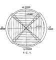
- Electrode switching allows a full 360° of inclination angle to be measured, in terms of deviation from level or plumb, (as shown in Figure 9) with the electrode configuration being chosen by the computing and control circuitry in accordance with the angle of inclination of the sensor.
- the processing circuitry When initialising an inclination measurement, the processing circuitry performs a measurement with an arbitrary pair of electrodes e.g. C,D chosen as the common pair as shown in Figures 5a,5b and 7. If the ratio R calculated by the computing circuitry is within an allowable range corresponding to ⁇ 50° (see Table 1), the measurement proceeds whereas if the measured ratio is outside the allowable range, the configuration is changed to that shown in Figure 8 and the measurement is then performed.
- a* is a function principally of any variation in initial liquid level with respect to the measuring electrodes, although other factors include the dimensions of the gap between the electrodes A and B (or C and D), and the resistance of the switches in the switch matrix; b is dependent upon manufacturing tolerance.
- ⁇ ′ is effectively zero when both sensing electrodes are equally immersed in the liquid, so that the capsule will have the greatest inherent accuracy at this position.
- the orthogonal disposition of the electrode pair A, B relative to electrode pair C, D gives the capsule two maximum accuracy positions which, in the described embodiments, are chosen to be level and plumb thus allowing measurements of maximum accuracy to be made at the most often measured angular positions, although the disposition of the electrode pairs may be chosen to give different maximum accuracy positions for specific applications.
Landscapes
- Chemical & Material Sciences (AREA)
- Organic Chemistry (AREA)
- Health & Medical Sciences (AREA)
- Engineering & Computer Science (AREA)
- Medicinal Chemistry (AREA)
- General Health & Medical Sciences (AREA)
- Life Sciences & Earth Sciences (AREA)
- Veterinary Medicine (AREA)
- Nuclear Medicine, Radiotherapy & Molecular Imaging (AREA)
- Chemical Kinetics & Catalysis (AREA)
- Pharmacology & Pharmacy (AREA)
- Animal Behavior & Ethology (AREA)
- General Chemical & Material Sciences (AREA)
- Public Health (AREA)
- Physics & Mathematics (AREA)
- Remote Sensing (AREA)
- Bioinformatics & Cheminformatics (AREA)
- Radar, Positioning & Navigation (AREA)
- General Physics & Mathematics (AREA)
- Proteomics, Peptides & Aminoacids (AREA)
- Biophysics (AREA)
- Pulmonology (AREA)
- Genetics & Genomics (AREA)
- Molecular Biology (AREA)
- Biochemistry (AREA)
- Cardiology (AREA)
- Dermatology (AREA)
- Rheumatology (AREA)
- Pain & Pain Management (AREA)
- Heart & Thoracic Surgery (AREA)
- Measurement Of Length, Angles, Or The Like Using Electric Or Magnetic Means (AREA)
- Measurement Of Levels Of Liquids Or Fluent Solid Materials (AREA)
- Investigating Or Analyzing Materials Using Thermal Means (AREA)
Abstract
Description
- This invention relates to a device and, more particularly, but not exclusively to a sensor for an electronic level or inclination gauge.
- Optical levels, more commonly called spirit levels, are well known and provide an optical indication of whether or not a surface is horizontal, based on the principle of an air bubble in a liquid-filled vial always seeking the highest point in the vial, the vial being slightly curved so that when at level, the bubble will always take up an equilibrium position. Such bubble levels, if disposed in a suitable frame, can also be used to provide an indication of whether or not a surface is vertical.
- However, such spirit levels are not capable of measuring deviations from horizontal or vertical outside a very limited range. Also, such spirit levels can be difficult to read accurately as the measurement of level or plumb depends on the ability of the user to determine the position of the bubble. Factors such as poor lighting or poor eyesight obviously affect this.
- An electronic spirit level has been proposed by Cantarella, in U.S. 4 167 818, which uses a capsule part-filled with a conductive liquid. Several electrodes are disposed within the capsule, the resistance between the electrodes being dependent on the position of the liquid within the capsule which, in turn, is dependent upon its inclination. A digital readout of angles of inclination from level and from plumb is provided. However, this level, again, is only usable over a limited range of angular deviation from horizontal or vertical.
- Capacitive devices, such as that disclosed in EP 35340 have also been proposed. The device of EP 35340 includes a capsule of generally cylindrical form part-filled with a liquid having a dielectric constant different from that of the remainder of the capsule. The capsule is provided with four electrodes, a single, primary, electrode being disposed on one end surface of the capsule and the three other, secondary, electrodes being disposed on the other end surface. Three sensing circuits including three oscillators are provided for sensing the capacitance between the first electrode and the three secondary electrodes.
- However, the three secondary electrodes each need a separate processing circuit. As each processing circuit tends to have its own individual characteristics, compensation for this is also necessary. This factor leads to additional manufacturing expense.
- US-A-4 167 818 discloses a sensor for an inclination measuring device, the sensor comprising:
a capsule (17) part-filled with a liquid (19);
first electrode means (A, B) comprising first and second electrodes (A, B) disposed within the capsule (17), the relative degree of immersion of the first and second electrodes (A, B) being variable, within a first angular range, with variation in the angle of inclination of the capsule (17) about a reference axis;
second electrode means (C, D) comprising third and fourth electrodes (C, D) disposed within the capsule (17), the relative degree of immersion of the third and fourth electrodes (C, D) being variable, within a second angular range, with variation in the angle of inclination of the capsule (17) about the reference axis;
and electrical means (20-27) electrically connected to said electrodes (A, B, C, D) to electrically sense the relative degrees of immersion of the electrodes (A, B, C, D) with the angle of inclination of the capsule (17) about the reference axis and hence to sense the inclination angle of the sensor. - US-A-4 028 815 discloses a toroidal accelerometer comprising a toroidal shaped housing having first and second oppositely disposed arcuate shaped electrodes and a third electrode which is a common electrode, all three electrodes being partially immersed in an electrolytic fluid and subject to differential wetting in accordance with the angle of tilt about a horizontal axis of rotation.
- The present invention provides a sensor as claimed in
claim 1 and an inclination measuring device as claimed in claim 5. Particular embodiments of the invention are set out in the respective dependent claims. - An embodiment of the invention will now be described, by way of example, with reference to the accompanying drawings in which:
- Figure 1 is a perspective view of a sensor capsule forming part of an embodiment of the invention;
- Figure 2 is a sectional view taken in the plane II-II′ of Figure 1;
- Figure 3 is an exploded sectional view taken through the plane III-III′ of Figure 1;
- Figures 4A-B are sectional views similar to Figure 2 of the capsule at different inclinations;
- Figures 5A and 5B show basic configurations of the sensing circuitry for the capsule shown in Figures 1 to 4;
- Figure 6 is a block diagram of the general arrangement of the sensing circuitry;
- Figure 7 shows a null measurement arrangement of the circuit shown in Figure 5;
- Figure 8 shows alternative arrangements of the sensing circuitry shown in Figures 5 to 7 for use in measuring an alternative range of angles;
- Figure 9 illustrates the angular range of the sensor referring to Figures 1 to 3, an inclination sensor, generally designated 1 is shown. The sensor comprises a
capsule 3 of generally cylindrical form. Thecapsule 3 is formed from two engageable non-conductive chemicallyinert plastics mouldings 5,7 formed preferably from thermoplastic polyester (e.g. a polybutylene terephthalate (PBT) for example VALOX) reinforced with 15-20% glass beads to provide strength and stability. - The
mouldings 5, 7 are ultra-sonically welded together to ensure a hermetic seal. The end faces 9,11 of themouldings 5,7 are formed of a thickness so as to be elastically deformable in response to pressure variations within thecapsule 3, as described hereinafter. - Within
mouldings 5,7, electrodes A,B and C,D formed from nickel are respectively disposed. Each electrode A-D is of generally semi-circular form and is formed on itsrespective moulding 5,7 preferably by vacuum deposition or hot foil blocking (although it is to be appreciated that other electrode-forming methods may be employed). The electrodes A,B (or C,D) are separated one from the other by an elongate gap 8 (or 10) so that the electrodes A,B (or C,D) are not in direct electrical contact. Thegaps - Alternatively, the capsule may be formed from two identical plastics discs, the electrodes being formed on the discs by silk screen printing, each disc then being connected to an open axial end of a hollow cylindrical plastics spacer, to form the capsule, the discs being rotated by 90° relative to one another to give the desired electrode configuration shown in figure 1.
- The electrodes A,B are rotated by 90° about a reference axis O of the capsule with respect to the electrodes C,D to allow measurement of angles through 360° as described hereinafter. A
conductive liquid 17 is disposed within thecapsule 3, preferably a mixture of distilled water and methanol and a salt, for example sodium acetate trihydrate (CH₃ COONa 3H₂O), thecapsule 3 being filled, at NTP, to half its volume. The remainder of the capsule is filled with air or an inert gas, for example argon. - The general mode of operation of the capsule is described with reference to Figures 4A and 4B for which a measurement using electrodes A,B as the sensing electrodes is illustrated. Figures 4A and 4B illustrate the
capsule 3 in a schematically shown mounting 19 having anedge 21 which is presented to a surface, the inclination of which is to be measured. One pair of electrodes in this case C,D are coupled together to form a common electrode and an alternating voltage is applied in turn to the electrodes A or B. The impedance and, more particularly, the resistance of the path between electrodes C,D and electrode A or electrode B is dependent upon the degree of immersion of electrode A or electrode B in theconductive liquid 17, the larger degree of immersion, the lower the resistance of the path. - Thus by measuring the resistances of the two paths, between electrodes C,D and electrode A and electrodes C,D and electrode B, the angle of inclination ϑ of the sensor can be calculated.
- More specifically as can be seen by comparison of Figures 4A and 4B, the total wetted area of electrodes A,B is always substantially a constant, so that, ignoring cross impedances:

- Where
ZT = The total resistance of the capsule
Z₁ = The resistance of path CD to A
Z₂ = The resistance of path CD to B
and

- So, the ratio, R, of the resistances Z1, Z2 is:


- Exemplary values of R are as follows:

- Circuitry for measuring the resistances Z₁, Z₂ will now be described with reference to Figure 5 which shows an
operational amplifier 107 in an inverting mode, with feedback resistor RF being connected between the inverting input terminal and output terminal of theamplifier 107. - Terminals C,D are commoned together and connected to
terminal 105 of OP-amp 107; in Figure 5A, terminal A is connected toA.C. source 120 while terminal B is connected to ground, with these terminals being swapped in Figure 5B. - Referring to Figure 5A, assuming VIN = 1 volt


operational amplifier 107.
combining 4 and 5:
... so that switching of terminals A,B will give a measurement of V₀₁ and V₀₂ from which R can be calculated which, byEquation 3, will give ϑ. - A circuit for generating a digital value corresponding to each of these variables is shown in Figure 6 and includes a
switch matrix 100 preferably formed as part of an Application Specific Integrated Circuit (ASIC) connected to electrodes A-D the matrix having further connections to: an input terminal having a drive input waveform applied fromsignal generator 120 viaband pass filter 130 of the form sin (2Πft) (t = time (secs) : f = frequency (Hertz)), anearth connection 103 and an output terminal connected tooperational amplifier 107. The switching functions of thematrix 100 are controlled bycontrol logic circuitry 150 via control bus 151 Electrode configuration instructions are sent to the control logic from computing circuitry (not shown) via the MODE lines. Connections equivalent to that illustrated in Figure 5b are shown in phantom lines. - Use of the switch matrix allows common excitation source and sensing circuitry to be used for all electrode configurations (which are described below), thus reducing potential excitation and sensing circuitry inaccuracies.
- The output from
operational amplifier 107 is fed to amultiplier 143. Themultiplier 143 is connected to an integrating analog to digital converter 152 which integrates the output of the multiplier and converts the integrated signal into a 14 bit digital signal, which is output to computing circuitry (not shown) for calculation of the inclination angle. - The
multiplier 143 is also supplied with reference signals from thesignal generator 120. The reference signals comprise two outputs (Phase and Quad) of the same frequency as the drive waveform and in phase quadrature with one another (sin(2Πft), cos(2Πft)). Phase and Quad need not be in phase with the drive signal. These signals are alternately supplied to themultiplier 143 through aswitch 154 controlled bycontrol logic unit 150. - The multiplier acts to multiply the waveform input from amplifier 107 (generally of the form A sin (2Πft + φ)) by the chosen reference signal so that its output is, sequentially:


- The signals represented by equations 12A and 12B are integrated over N cycles of the signal waveform (N being an integer) with respect to time by integrator 152, giving:

- The circuit provides a 14 bit output proportional to these values. As can be seen, squaring 13A and 13B and adding gives:


multiplier 143. - The multiplier may be replaced by logic, which gates the input signal from
op amp 107 with a reference signal which pulses on, then off, at half cycle intervals of the drive signal sin(2Πft). Gating the input signal in this way has the same effect as multiplying the input signal by a sinusoidal signal of the same frequency as the device signal provided that the input signal is substantially free from harmonics and D.C. terms. - Gating the input signal, alternately, with two such reference signals in phase quadrature will then provide the two outputs of equations 12a and b.
- In an alternative configuration, a single reference signal (sin 2Πft) which is in phase with the drive signal (sin 2Πft) may be applied to
multiplier 143. The resulting multiplied output will then only contain components of the waveform input fromOp Amp 107 which are independent of the arbitrary phase Φ (effectively Φ=0 for this measurement) so that, with reference to equation 13a, the integrated output will be KVocos 0 = KVo, so a quadrature measurment is unnecessary. - In order to compensate for DC offsets present in the circuitry, and coherent noise pickup, the control logic is also operable in a calibration (NULL) mode, for measuring of the offset prior to each resistance measurement. For this, the circuitry is configured as shown in Figure 7, with terminals A,B both being connected to ground or another known potential and the offset Voln (or Vo2n which is equivalent to Voln) being measured as appropriate.
- In all, the following sequence of events (initiated in response to a start signal (START) from the computing circuitry) is required for one inclination measurement to be made:
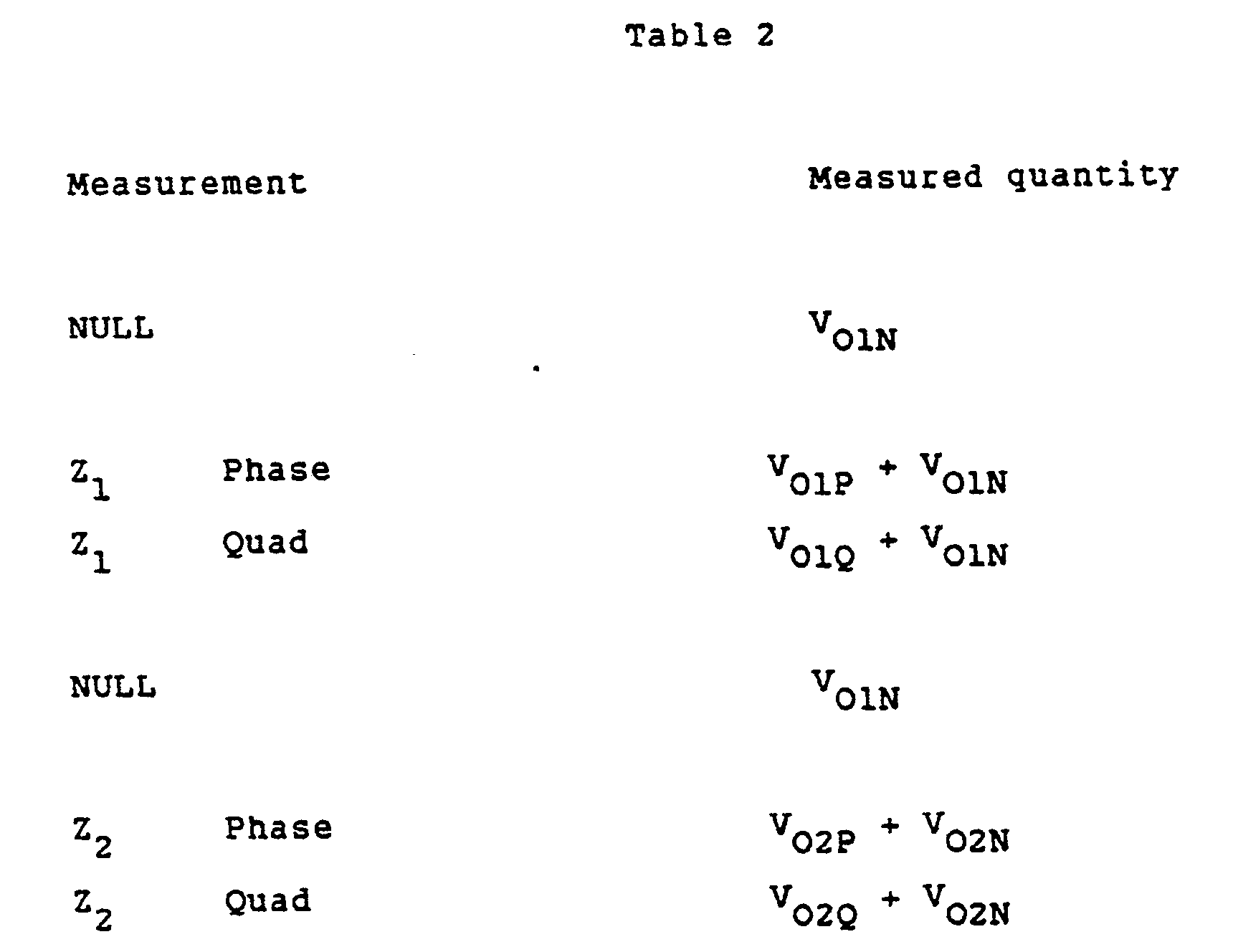
- Alternatively, if the drive and reference signals are in phase, as previously described, only the measurement of Z₁ phase and Z₂ phase a NULL are necessary.
- When a measurement is finished, the control logic sends a signal to the computing circuitry by means of the data ready (DR) line.
- Electrodes A,B are used for sensing angles up to ± 50° from the horizontal in the configuration illustrated in Figures 4A and 4B. For angles of inclination greater than these limits, the control logic reconfigures the electrodes so that the electrodes A,B become the common electrode and the orthogonally disposed electrodes C,D become the sensing electrodes, the sensor measuring angles in this configuration in the range ± 50° from vertical. The electrode configuration for these measurements, together with the offset configuration are shown in Figure 8A-C. The sequence of events for the measurement of inclination for the electrodes in this configuration is analogous to that previously described with reference to Table 2.
- Use of such electrode switching allows a full 360° of inclination angle to be measured, in terms of deviation from level or plumb, (as shown in Figure 9) with the electrode configuration being chosen by the computing and control circuitry in accordance with the angle of inclination of the sensor. When initialising an inclination measurement, the processing circuitry performs a measurement with an arbitrary pair of electrodes e.g. C,D chosen as the common pair as shown in Figures 5a,5b and 7. If the ratio R calculated by the computing circuitry is within an allowable range corresponding to ± 50° (see Table 1), the measurement proceeds whereas if the measured ratio is outside the allowable range, the configuration is changed to that shown in Figure 8 and the measurement is then performed.
- The inventors have found that the sensor described is subject to some measurement inaccuracies, which can be expressed in terms of measured angle ϑ′ and actual angle ϑ as follows:

- Where a* is a function principally of any variation in initial liquid level with respect to the measuring electrodes, although other factors include the dimensions of the gap between the electrodes A and B (or C and D), and the resistance of the switches in the switch matrix; b is dependent upon manufacturing tolerance. ϑ′ is effectively zero when both sensing electrodes are equally immersed in the liquid, so that the capsule will have the greatest inherent accuracy at this position. The orthogonal disposition of the electrode pair A, B relative to electrode pair C, D gives the capsule two maximum accuracy positions which, in the described embodiments, are chosen to be level and plumb thus allowing measurements of maximum accuracy to be made at the most often measured angular positions, although the disposition of the electrode pairs may be chosen to give different maximum accuracy positions for specific applications.
Claims (17)
a capsule (3) part-filled with a liquid (17);
first electrode means (A, B) comprising a first electrode (A) and a second electrode (B) disposed within the capsule (3), the relative degree of immersion of the first and second electrodes (A, B) being variable with variation in the angle of inclination of the capsule (3) about a reference axis (O), so that the degree of immersion of the first electrode (A) increases and that of the second electrode (B) decreases in one direction, and vice versa, within a first angular range (90° +/- 50°);
second electrode means (C, D) comprising a third electrode (C) and a fourth electrode (D) disposed within the capsule (3), the relative degree of immersion of the third and fourth electrodes (C, D) being variable with variation in the angle of inclination of the capsule (3) about the reference axis (O), so that the degree of immersion of the third electrode (C) increases and that of the fourth electrode (D) decreases in one direction, and vice versa, within a second angular range (0° +/- 50°);
and electrical means (105, 107, 120, RF) electrically connected to said electrodes (A, B, C, D) for electrically sensing the relative degrees of immersion of the electrodes (A, B, C, D) and hence for determining the inclination angle of the sensor;
characterised in that:- (a) said electrical means (105, 107, 120, RF) is adapted to be operative, when the angle of inclination of the capsule (3) about the reference axis (O) is within the first angular range (90° +/- 50°), for electrically sensing the relative degree of immersion of the first and second electrodes (A, B) and for determining, from the relative degree of immersion of the first and second electrodes (A, B), the angle of inclination of the capsule (3) about the reference axis (O) relative to a first reference angle (90°), which is the angle at which the first and second electrodes (A,B) of said first electrode means are substantially equally immersed in the liquid (17); (b) said electrical means (105, 107, 120, RF) is adapted to be operative, when the angle of inclination of the capsule (3) about the reference axis (O) is within the second angular range (0° +/- 50°), for electrically sensing the relative degree of immersion of the third and fourth electrodes (C, D) and for determining, from the relative degree of immersion of the third and fourth electrodes (C, D), the angle of inclination of the capsule (3) about the reference axis (O) relative to a second reference angle (0°), which is different from said first reference angle (90°) and which is the angle at which the third and fourth electrodes (C,D) of said second electrode means are substantially equally immersed in the liquid (17); and (c) any angle of inclination (0°-360°) of the capsule (3) about the reference axis (O) is included within at least one of said ranges (90° +/- 50°; 0° +/- 50°).
a drive source (120) for generating a drive signal to be applied to the capsule (3),
processing means (107, 143, 152) for processing an output signal from the capsule (3).
switch means (100), arranged to select any one of the electrodes (A-D) and to connect the selected electrode to the drive source (120) whereby the drive signal is applied to the capsule (3) through the selected electrode (A-D), the drive signal being modified by the impedance of the liquid (17) between the selected electrode (A-D) and a common electrode to form the output signal, the impedance being dependent upon the degree of immersion of the selected electrode in the liquid, and
control means (150), for controlling the operation of the switch means.
amplifier means (107) for amplifying the output signal, multiplier means (143), for multiplying the amplified signal, sequentially, by first and second reference signals, to generate first and second multiplied signals, the first and second reference signals including a component having the same frequency as the drive signal and the reference signals being in phase quadrature with one another: and
integrating means (152), for integrating each multiplied signal over a predetermined number of cycles of the multiplied signal to form first and second integrated signals; and
calculation means, responsive to the integrating means, for deriving the inclination angle from the integrated signals associated with the sequentially selected electrodes.
amplifier means (107), for amplifying a said modified signal,
multiplier means (143) for multiplying the amplified signal by a reference signal including a component in phase with and of the same frequency as the drive signal to form a multiplied signal; and
integrating means (152) for integrating the output of the multiplier means over a predetermined number of cycles of the signal, to form an integrated signal; and
calculation means, responsive to the integrating means, for deriving the inclination angle from the integrated signals associated with the sequentially selected electrodes.
Applications Claiming Priority (2)
| Application Number | Priority Date | Filing Date | Title |
|---|---|---|---|
| GB8601586A GB2186693B (en) | 1986-01-23 | 1986-01-23 | Inclination sensor |
| GB8601586 | 1986-01-23 |
Publications (2)
| Publication Number | Publication Date |
|---|---|
| EP0291507A1 EP0291507A1 (en) | 1988-11-23 |
| EP0291507B1 true EP0291507B1 (en) | 1991-10-23 |
Family
ID=10591808
Family Applications (2)
| Application Number | Title | Priority Date | Filing Date |
|---|---|---|---|
| EP87900859A Expired - Lifetime EP0291507B1 (en) | 1986-01-23 | 1987-01-23 | Electronic inclinometer |
| EP87900858A Expired - Lifetime EP0290452B1 (en) | 1986-01-23 | 1987-01-23 | Electronic inclinometer |
Family Applications After (1)
| Application Number | Title | Priority Date | Filing Date |
|---|---|---|---|
| EP87900858A Expired - Lifetime EP0290452B1 (en) | 1986-01-23 | 1987-01-23 | Electronic inclinometer |
Country Status (9)
| Country | Link |
|---|---|
| US (2) | US5172481A (en) |
| EP (2) | EP0291507B1 (en) |
| JP (2) | JP2785934B2 (en) |
| KR (2) | KR950014819B1 (en) |
| CN (2) | CN87100814A (en) |
| CA (3) | CA1292049C (en) |
| DE (2) | DE3774120D1 (en) |
| GB (2) | GB2186693B (en) |
| WO (2) | WO1987004514A1 (en) |
Families Citing this family (53)
| Publication number | Priority date | Publication date | Assignee | Title |
|---|---|---|---|---|
| US5335190A (en) * | 1987-06-22 | 1994-08-02 | Wedge Innovations Incorporated | Inclinometer which is rescalable through the use of multiple angles |
| IT1218980B (en) * | 1988-01-27 | 1990-04-24 | Marelli Autronica | ELECTRIC INCLINATION SENSOR AND DETECTION CIRCUIT FOR SUCH SENSOR |
| US5083383A (en) * | 1989-03-21 | 1992-01-28 | Zircon International, Inc. | Electronic capacitance level with automatic electrode selection |
| EP0464145B1 (en) * | 1989-03-21 | 1996-07-17 | Zircon International, Inc. | Electronic capacitive level with automatic electrode selection |
| EP0497791A4 (en) * | 1989-10-17 | 1992-10-07 | Wedge Innovations, Inc. | Rescaleable inclinometer |
| GB2241579B (en) * | 1990-02-20 | 1994-04-27 | Secr Defence | A roll measuring meter |
| US5390104A (en) * | 1990-04-02 | 1995-02-14 | Fulton; Francis M. | Adaptive control man-augmentation system for a suspended work station |
| US5174033A (en) * | 1990-06-18 | 1992-12-29 | The Charles Machine Works, Inc. | Angle sensor for a steerable boring tool |
| US5133417A (en) * | 1990-06-18 | 1992-07-28 | The Charles Machine Works, Inc. | Angle sensor using thermal conductivity for a steerable boring tool |
| EP0492330A1 (en) * | 1990-12-24 | 1992-07-01 | Deutsche Aerospace AG | Capacitive inclination sensor |
| US5237753A (en) * | 1992-05-18 | 1993-08-24 | Lucas Sensing Systems, Inc. | Capacitive gravity sensor and inclinometer |
| US5479716A (en) * | 1994-07-12 | 1996-01-02 | Design & Test Technology, Inc. | Capacitive based gravity sensor |
| US5612679A (en) * | 1995-03-14 | 1997-03-18 | Burgess; Lester E. | Electrolytic tilt sensor |
| US5630280A (en) * | 1995-05-01 | 1997-05-20 | The Fredericks Company | Dual axis electrolytic tilt sensor |
| US5802728A (en) * | 1995-08-17 | 1998-09-08 | Watson Industries, Inc. | Liquid level and angle detector |
| US5726359A (en) | 1995-11-29 | 1998-03-10 | Digital Control, Inc. | Orientation sensor especially suitable for use in an underground boring device |
| US5680708A (en) * | 1996-01-16 | 1997-10-28 | Precision Navigation, Inc. | Temperature compensated tilt sensor |
| US5907278A (en) * | 1996-12-17 | 1999-05-25 | Kavlico Corporation | Capacitive sensor assembly with soot build-up inhibiting coating |
| US5900810A (en) * | 1996-12-17 | 1999-05-04 | Kavlico Corporation | Capacitive sensor assembly |
| AU5722198A (en) * | 1996-12-20 | 1998-07-17 | Ep Technologies Inc | Unified switching system for electrophysiological stimulation and signal recording and analysis |
| US5992032A (en) * | 1997-02-24 | 1999-11-30 | Chung-Shan Institute Of Science & Technology | Method and apparatus for inclination measurement using piezoelectric effect |
| US5929754A (en) * | 1997-12-03 | 1999-07-27 | Kavlico Corporation | High-sensitivity capacitive oil deterioration and level sensor |
| JP4014326B2 (en) | 1999-02-18 | 2007-11-28 | 本田技研工業株式会社 | Capacitive tilt sensor |
| US6548771B1 (en) * | 1999-08-12 | 2003-04-15 | Seiko Instruments Inc. | Multipole attitude detector switch with liquid contact |
| RU2178547C2 (en) * | 1999-12-21 | 2002-01-20 | ОАО Омское специальное конструкторское бюро приборов | Inclination angle sensor |
| US20040016137A1 (en) * | 2000-04-06 | 2004-01-29 | Barsky Barry E. | Electrolytic tilt sensor having a meniscus inhibitor |
| US6249984B1 (en) | 2000-04-06 | 2001-06-26 | The Fredericks Company | Electrolytic tilt sensor having a metallic envelope |
| KR20020078425A (en) * | 2001-04-09 | 2002-10-18 | 한국표준과학연구원 | Capacitive sensor for measuring of inclination |
| AUPS263802A0 (en) * | 2002-05-30 | 2002-06-20 | Dear, Henry Charles | Adjusting the null position of levelling apparatus |
| US7360424B2 (en) * | 2002-06-20 | 2008-04-22 | Ubukata Industries, Co., Ltd. | Capacitance-type liquid sensor |
| US7055255B2 (en) * | 2003-10-29 | 2006-06-06 | Hiram Diaz | Inclination angle reader and method for using same |
| DE102005025908B3 (en) * | 2005-06-06 | 2006-11-09 | Hahn-Schickard-Gesellschaft für angewandte Forschung e.V. | Capacitative sensor to measure values, e.g. for vehicle tilts and automatic machines, has two electrode pairs with a moving component between them with measurement of difference capacities at part-capacitors formed by the electrode array |
| EP1955013B1 (en) | 2005-12-02 | 2018-10-10 | 059312 N.B. Inc. | Shape-acceleration measurement device and method |
| EP2051043A1 (en) * | 2007-10-17 | 2009-04-22 | SOLA-Messwerkzeuge GmbH | Airlessly sealed vial |
| US7886451B2 (en) * | 2008-03-05 | 2011-02-15 | The Fredericks Company | Integral electrode tilt sensor and method for making same |
| JP2009264909A (en) * | 2008-04-24 | 2009-11-12 | Nanocreate Co Ltd | Electrostatic device method for manufacturing and electrostatic device |
| WO2009136947A1 (en) * | 2008-05-09 | 2009-11-12 | Litchfield William L | Level |
| US8155812B2 (en) * | 2008-05-12 | 2012-04-10 | Smith David Q | Floating dock deflection management systems |
| USD619188S1 (en) * | 2009-04-09 | 2010-07-06 | David Omley | Archery inclinometer |
| US8800155B2 (en) * | 2011-04-22 | 2014-08-12 | Jack A. Ekchian | Displacement sensor with reduced hysteresis |
| CN103047967A (en) * | 2011-10-17 | 2013-04-17 | 天津市亚安科技股份有限公司 | Angle testing method |
| CN102519554A (en) * | 2011-11-21 | 2012-06-27 | 程有信 | Capacitor type differential operation floater liquid level sensor |
| CN102564398B (en) * | 2011-12-29 | 2013-09-18 | 东南大学 | Micro mechanical capacitor type dip sensor |
| KR200471538Y1 (en) | 2013-11-08 | 2014-02-28 | 이재석 | Dice having angle measuring function |
| CZ309210B6 (en) * | 2013-11-15 | 2022-05-25 | Linet, Spol. S R. O. | Bed with tilt indicator |
| CN103837134A (en) * | 2014-03-06 | 2014-06-04 | 湖南科技学院 | Differential capacitor type obliquity sensor |
| EP3264982A4 (en) * | 2015-03-04 | 2018-09-26 | California Institute of Technology | Position sensing and guiding system |
| US10088311B2 (en) * | 2016-09-15 | 2018-10-02 | Texas Instruments Incorporated | Analog floating-gate inclinometer |
| CN106595590B (en) * | 2016-12-13 | 2019-04-30 | 武汉理工大学 | A bidirectional inclinometer based on the principle of balance bar |
| US11170625B2 (en) | 2018-05-18 | 2021-11-09 | California Institute Of Technology | Head positioner for retinal surgery patients |
| CN110082498A (en) * | 2019-04-08 | 2019-08-02 | 三峡大学 | A kind of landslide monitoring data unmanned plane acquisition system based on wireless sensor Internet of Things |
| CN111912397B (en) * | 2020-07-31 | 2022-02-22 | 合肥工业大学 | System and method for measuring plane and line segment direction by means of cylindrical cavity liquid section |
| CN112229379B (en) * | 2020-09-25 | 2022-09-27 | 南京信息职业技术学院 | Electrolyte fan cylinder shape variable inclination angle tester |
Family Cites Families (12)
| Publication number | Priority date | Publication date | Assignee | Title |
|---|---|---|---|---|
| US2584917A (en) * | 1950-10-09 | 1952-02-05 | Edward D Powell | Level |
| US3604275A (en) * | 1968-10-23 | 1971-09-14 | Sperry Rand Corp | Toroidal electrolytic sensor |
| US3906471A (en) * | 1973-09-12 | 1975-09-16 | Sun Oil Co Pennsylvania | High side meter |
| US4028815A (en) * | 1974-11-18 | 1977-06-14 | Sperry Rand Corporation | Temperature compensated toroidal accelerometer |
| US4167818A (en) * | 1978-02-03 | 1979-09-18 | Robert Cantarella | Electronic inclination gauge |
| GB2048473B (en) * | 1979-05-01 | 1983-03-16 | Standard Telephones Cables Ltd | Thermostat capsule |
| JPS5688294A (en) * | 1979-12-21 | 1981-07-17 | Tokyo Shibaura Electric Co | Electronic range |
| GB2070774A (en) * | 1980-02-28 | 1981-09-09 | Pa Management Consult | Capactive clinometer |
| EP0117226A3 (en) * | 1983-01-28 | 1985-10-02 | Max Engler | Apparatus for measuring deviations from the vertical and its use |
| JPS6026164A (en) * | 1983-07-25 | 1985-02-09 | Hitachi Constr Mach Co Ltd | Trouble diagnoser for fuel injection pump |
| DD226068A1 (en) * | 1984-05-28 | 1985-08-14 | Suhl Feinmesszeugfab Veb | CAPACITIVE TILT AND LEVEL MEASUREMENT DEVICE |
| JPS61193015A (en) * | 1985-01-31 | 1986-08-27 | ルーカス・インダストリーズ・インコーポレイテッド | Inclinometer |
-
1986
- 1986-01-23 GB GB8601586A patent/GB2186693B/en not_active Expired - Lifetime
-
1987
- 1987-01-22 CA CA000527959A patent/CA1292049C/en not_active Expired - Fee Related
- 1987-01-22 CA CA000527960A patent/CA1320748C/en not_active Expired - Fee Related
- 1987-01-23 EP EP87900859A patent/EP0291507B1/en not_active Expired - Lifetime
- 1987-01-23 KR KR1019870700860A patent/KR950014819B1/en not_active Expired - Fee Related
- 1987-01-23 CN CN198787100814A patent/CN87100814A/en active Pending
- 1987-01-23 JP JP62500893A patent/JP2785934B2/en not_active Expired - Lifetime
- 1987-01-23 WO PCT/GB1987/000041 patent/WO1987004514A1/en not_active Ceased
- 1987-01-23 JP JP62500889A patent/JP2634832B2/en not_active Expired - Lifetime
- 1987-01-23 US US07/223,240 patent/US5172481A/en not_active Expired - Fee Related
- 1987-01-23 DE DE8787900859T patent/DE3774120D1/en not_active Expired - Fee Related
- 1987-01-23 DE DE8787900858T patent/DE3770461D1/en not_active Expired - Fee Related
- 1987-01-23 KR KR1019870700868A patent/KR960013449B1/en not_active Expired - Fee Related
- 1987-01-23 WO PCT/GB1987/000042 patent/WO1987004515A1/en not_active Ceased
- 1987-01-23 EP EP87900858A patent/EP0290452B1/en not_active Expired - Lifetime
- 1987-01-23 US US07/223,241 patent/US5170567A/en not_active Expired - Fee Related
- 1987-01-23 CN CN198787100808A patent/CN87100808A/en active Pending
-
1989
- 1989-11-10 GB GB8925486A patent/GB2222686B/en not_active Expired - Lifetime
-
1993
- 1993-04-28 CA CA000616623A patent/CA1330873C/en not_active Expired - Fee Related
Also Published As
| Publication number | Publication date |
|---|---|
| EP0290452A1 (en) | 1988-11-17 |
| GB2186693A (en) | 1987-08-19 |
| GB2186693B (en) | 1990-09-05 |
| US5172481A (en) | 1992-12-22 |
| GB8601586D0 (en) | 1986-02-26 |
| CN87100808A (en) | 1987-09-02 |
| GB2222686B (en) | 1990-08-29 |
| KR950014819B1 (en) | 1995-12-15 |
| KR960013449B1 (en) | 1996-10-05 |
| JPH01501415A (en) | 1989-05-18 |
| JP2634832B2 (en) | 1997-07-30 |
| JP2785934B2 (en) | 1998-08-13 |
| WO1987004514A1 (en) | 1987-07-30 |
| EP0290452B1 (en) | 1991-05-29 |
| CA1292049C (en) | 1991-11-12 |
| EP0291507A1 (en) | 1988-11-23 |
| DE3774120D1 (en) | 1991-11-28 |
| KR880700925A (en) | 1988-04-13 |
| US5170567A (en) | 1992-12-15 |
| WO1987004515A1 (en) | 1987-07-30 |
| KR880700924A (en) | 1988-04-13 |
| GB2222686A (en) | 1990-03-14 |
| JPH01501414A (en) | 1989-05-18 |
| GB8925486D0 (en) | 1989-12-28 |
| CN87100814A (en) | 1987-12-02 |
| DE3770461D1 (en) | 1991-07-04 |
| CA1320748C (en) | 1993-07-27 |
| CA1330873C (en) | 1994-07-26 |
Similar Documents
| Publication | Publication Date | Title |
|---|---|---|
| US5172481A (en) | Electronic inclinometer | |
| JP2934672B2 (en) | Capacitive detector | |
| US4642555A (en) | Differential capacitance detector | |
| CA1286746C (en) | Two-axis differential capacitance inclinometer | |
| RU2144680C1 (en) | Shielded variable-capacitance transducer | |
| US4937518A (en) | Electrical inclination sensor and a monitoring circuit for the sensor | |
| US4641434A (en) | Inclination measuring device | |
| US3992951A (en) | Compensated toroidal accelerometer | |
| US4628612A (en) | Tilt angle detection device | |
| JPH02504079A (en) | capacitive transducer | |
| JPH09119832A (en) | Output-signal generating circuit | |
| JPH0475446B2 (en) | ||
| US5869971A (en) | Method and apparatus for ratiometric measurement of hematocrit | |
| EP0243011B1 (en) | Electronic inclination gauge | |
| TW522221B (en) | Tilting detector | |
| US4660290A (en) | Inclination measuring instrument | |
| EP0464145B1 (en) | Electronic capacitive level with automatic electrode selection | |
| US6382025B1 (en) | Rotational rate sensor | |
| JPS6336246Y2 (en) | ||
| JP2807827B2 (en) | Capacitance type distance meter | |
| JPS59216012A (en) | Electrostatic capacity type inclination sensor | |
| RU2152044C1 (en) | Transducer of mechanical oscillation parameters | |
| JP2729321B2 (en) | Capacitance type measuring instrument | |
| SU679895A1 (en) | Device for measuring complex conductivity constituents of two-pole circuits | |
| RU1789855C (en) | Inclinometer |
Legal Events
| Date | Code | Title | Description |
|---|---|---|---|
| PUAI | Public reference made under article 153(3) epc to a published international application that has entered the european phase |
Free format text: ORIGINAL CODE: 0009012 |
|
| 17P | Request for examination filed |
Effective date: 19880721 |
|
| AK | Designated contracting states |
Kind code of ref document: A1 Designated state(s): CH DE FR IT LI NL |
|
| 17Q | First examination report despatched |
Effective date: 19900228 |
|
| RAP1 | Party data changed (applicant data changed or rights of an application transferred) |
Owner name: THE STANLEY WORKS |
|
| GRAA | (expected) grant |
Free format text: ORIGINAL CODE: 0009210 |
|
| AK | Designated contracting states |
Kind code of ref document: B1 Designated state(s): CH DE FR IT LI NL |
|
| PG25 | Lapsed in a contracting state [announced via postgrant information from national office to epo] |
Ref country code: NL Effective date: 19911023 Ref country code: LI Effective date: 19911023 Ref country code: CH Effective date: 19911023 |
|
| ITF | It: translation for a ep patent filed | ||
| REF | Corresponds to: |
Ref document number: 3774120 Country of ref document: DE Date of ref document: 19911128 |
|
| ET | Fr: translation filed | ||
| REG | Reference to a national code |
Ref country code: CH Ref legal event code: PL |
|
| NLV1 | Nl: lapsed or annulled due to failure to fulfill the requirements of art. 29p and 29m of the patents act | ||
| PLBE | No opposition filed within time limit |
Free format text: ORIGINAL CODE: 0009261 |
|
| STAA | Information on the status of an ep patent application or granted ep patent |
Free format text: STATUS: NO OPPOSITION FILED WITHIN TIME LIMIT |
|
| 26N | No opposition filed | ||
| PGFP | Annual fee paid to national office [announced via postgrant information from national office to epo] |
Ref country code: DE Payment date: 19991231 Year of fee payment: 14 |
|
| PGFP | Annual fee paid to national office [announced via postgrant information from national office to epo] |
Ref country code: FR Payment date: 20000112 Year of fee payment: 14 |
|
| PG25 | Lapsed in a contracting state [announced via postgrant information from national office to epo] |
Ref country code: FR Free format text: LAPSE BECAUSE OF NON-PAYMENT OF DUE FEES Effective date: 20010928 |
|
| PG25 | Lapsed in a contracting state [announced via postgrant information from national office to epo] |
Ref country code: DE Free format text: LAPSE BECAUSE OF NON-PAYMENT OF DUE FEES Effective date: 20011101 |
|
| REG | Reference to a national code |
Ref country code: FR Ref legal event code: ST |
|
| PG25 | Lapsed in a contracting state [announced via postgrant information from national office to epo] |
Ref country code: IT Free format text: LAPSE BECAUSE OF NON-PAYMENT OF DUE FEES;WARNING: LAPSES OF ITALIAN PATENTS WITH EFFECTIVE DATE BEFORE 2007 MAY HAVE OCCURRED AT ANY TIME BEFORE 2007. THE CORRECT EFFECTIVE DATE MAY BE DIFFERENT FROM THE ONE RECORDED. Effective date: 20050123 |