EP0290201A1 - Power transmitting system for a four-wheel drive vehicle - Google Patents
Power transmitting system for a four-wheel drive vehicle Download PDFInfo
- Publication number
- EP0290201A1 EP0290201A1 EP88303861A EP88303861A EP0290201A1 EP 0290201 A1 EP0290201 A1 EP 0290201A1 EP 88303861 A EP88303861 A EP 88303861A EP 88303861 A EP88303861 A EP 88303861A EP 0290201 A1 EP0290201 A1 EP 0290201A1
- Authority
- EP
- European Patent Office
- Prior art keywords
- drive shaft
- differential
- shaft
- housing
- viscous coupling
- Prior art date
- Legal status (The legal status is an assumption and is not a legal conclusion. Google has not performed a legal analysis and makes no representation as to the accuracy of the status listed.)
- Granted
Links
- 230000008878 coupling Effects 0.000 claims abstract description 21
- 238000010168 coupling process Methods 0.000 claims abstract description 21
- 238000005859 coupling reaction Methods 0.000 claims abstract description 21
- 230000005540 biological transmission Effects 0.000 claims abstract description 20
- 239000012530 fluid Substances 0.000 description 2
- 238000010586 diagram Methods 0.000 description 1
- 238000012986 modification Methods 0.000 description 1
- 230000004048 modification Effects 0.000 description 1
Images
Classifications
-
- B—PERFORMING OPERATIONS; TRANSPORTING
- B60—VEHICLES IN GENERAL
- B60K—ARRANGEMENT OR MOUNTING OF PROPULSION UNITS OR OF TRANSMISSIONS IN VEHICLES; ARRANGEMENT OR MOUNTING OF PLURAL DIVERSE PRIME-MOVERS IN VEHICLES; AUXILIARY DRIVES FOR VEHICLES; INSTRUMENTATION OR DASHBOARDS FOR VEHICLES; ARRANGEMENTS IN CONNECTION WITH COOLING, AIR INTAKE, GAS EXHAUST OR FUEL SUPPLY OF PROPULSION UNITS IN VEHICLES
- B60K17/00—Arrangement or mounting of transmissions in vehicles
- B60K17/34—Arrangement or mounting of transmissions in vehicles for driving both front and rear wheels, e.g. four wheel drive vehicles
- B60K17/344—Arrangement or mounting of transmissions in vehicles for driving both front and rear wheels, e.g. four wheel drive vehicles having a transfer gear
- B60K17/346—Arrangement or mounting of transmissions in vehicles for driving both front and rear wheels, e.g. four wheel drive vehicles having a transfer gear the transfer gear being a differential gear
- B60K17/3462—Arrangement or mounting of transmissions in vehicles for driving both front and rear wheels, e.g. four wheel drive vehicles having a transfer gear the transfer gear being a differential gear with means for changing distribution of torque between front and rear wheels
- B60K17/3465—Arrangement or mounting of transmissions in vehicles for driving both front and rear wheels, e.g. four wheel drive vehicles having a transfer gear the transfer gear being a differential gear with means for changing distribution of torque between front and rear wheels self-actuated means, e.g. differential locked automatically by difference of speed
-
- F—MECHANICAL ENGINEERING; LIGHTING; HEATING; WEAPONS; BLASTING
- F16—ENGINEERING ELEMENTS AND UNITS; GENERAL MEASURES FOR PRODUCING AND MAINTAINING EFFECTIVE FUNCTIONING OF MACHINES OR INSTALLATIONS; THERMAL INSULATION IN GENERAL
- F16H—GEARING
- F16H2200/00—Transmissions for multiple ratios
- F16H2200/0017—Transmissions for multiple ratios specially adapted for four-wheel-driven vehicles
-
- F—MECHANICAL ENGINEERING; LIGHTING; HEATING; WEAPONS; BLASTING
- F16—ENGINEERING ELEMENTS AND UNITS; GENERAL MEASURES FOR PRODUCING AND MAINTAINING EFFECTIVE FUNCTIONING OF MACHINES OR INSTALLATIONS; THERMAL INSULATION IN GENERAL
- F16H—GEARING
- F16H3/00—Toothed gearings for conveying rotary motion with variable gear ratio or for reversing rotary motion
- F16H3/02—Toothed gearings for conveying rotary motion with variable gear ratio or for reversing rotary motion without gears having orbital motion
- F16H3/08—Toothed gearings for conveying rotary motion with variable gear ratio or for reversing rotary motion without gears having orbital motion exclusively or essentially with continuously meshing gears, that can be disengaged from their shafts
- F16H3/087—Toothed gearings for conveying rotary motion with variable gear ratio or for reversing rotary motion without gears having orbital motion exclusively or essentially with continuously meshing gears, that can be disengaged from their shafts characterised by the disposition of the gears
- F16H3/089—Toothed gearings for conveying rotary motion with variable gear ratio or for reversing rotary motion without gears having orbital motion exclusively or essentially with continuously meshing gears, that can be disengaged from their shafts characterised by the disposition of the gears all of the meshing gears being supported by a pair of parallel shafts, one being the input shaft and the other the output shaft, there being no countershaft involved
Definitions
- the present invention relates to a system for transmitting the power of an engine to four driving wheels of a four-wheel drive vehicle.
- the central differential operates to uniformly distribute the torque of an engine to front wheels and to rear wheels.
- Japanese Patent Application Laid-Open 59-179425 discloses a system in which front wheels are connected to rear wheels by a fluid clutch or a viscous clutch. When rotational speeds of rear wheels are lower than a predetermined speed range compared with those of front wheels, the rear wheels are driven by the power for front wheel drive through a one-way clutch.
- the viscous clutch In the latter system, it is difficult to determine the capacity of the viscous clutch for setting a viscous mode and a hump mode. Further, in order to obtain an appropriate operational characteristic, the viscous clutch must have a comparatively large capacity.
- the present invention seeks to provide a power system which is compact in size and automatically operates to restrict the differential operation of the central differential in accordance with driving conditions.
- a power transmitting system for a four-wheel drive vehicle oomprising a transmission, a central differential having a casing, a pinion shaft secured to the casing, a pair of pinion gears mounted on the pinion shaft, and a pair of differential gears engaged with the pinion gears, and a viscous coupling having a housing and hub provided in the housing.
- the system of the present invention is characterized in that the viscous coupling is provided coaxially with the central differential, a first drive shaft is provided passing through axes of the central differential and the viscous coupling, the pinion shaft comprises a pair of shafts, an inner end of each of which is rotatably mounted on the first drive shaft, an output shaft of the transmission is operatively connected to the casing of the differential, one of the differential gears is secured to the first drive shaft, and the first drive shaft is operatively connected to either front or rear wheels, the other differential gear is secured to the housing of the viscous coupling, the housing is operatively connected to the other wheels, and the hub is secured to the first drive shaft.
- the output shaft is a cylindrical shaft in which a second drive shaft for the other wheels is rotatably mounted, and the housing of the viscous coupling connected to the second drive shaft.
- the housing is preferably rotatably mounted on the first drive shaft through a bearing.
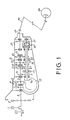
- Figure 1 shows a power transmission system for a four-wheel drive motor vehicle to which the present embodiment is applied.
- An engine 1 is longitudinally mounted on the motor vehicle at a front portion thereof, thus forming a transaxle type.
- the power transmission system housed in a transmission case comprises a clutch 2, sub transmission 4, main transmission 8 and transfer device 20.
- the sub transmission 4 connected to the clutch 2 through a drive shaft 3 has a reduction gears 6 disposed between the drive shaft 3 and an input shaft 5, and a selector mechanism 7.
- the sub transmission 4 is adapted to selectively operate to directly engage the drive shaft 3 with the input shaft 5 for providing a high speed range and to engage the drive shaft 3 with the input shaft 5 through the reduction gears 6 for providing a low speed range.
- the main transmission 8 connected to the input shaft 5 has a tubular output shaft 9 parallel with the input shaft 5, five pairs of change-speed gears 10 to 14 corresponding to first to fifth speed gears, synchronizers 15 to 17, and a reverse drive gear (not shown).
- a front drive shaft 18 is rotatably supported in the output shaft 9.
- a drive pinion 9a at the front end of the shaft 18 meshes with a crown gear of a front differential 19 so as to transmit the power to front wheels.
- the transfer device 20 is disposed behind the main transmission 8 at the rear end of the output shaft 9.
- the transfer device 20 has a drive shaft 21 disposed in alignment with the front drive shaft 18, and is connected to a rear drive shaft 23 through transfer gears 22.
- the rear drive shaft 23 is disposed in parallel with the front drive shaft 18.
- the rear drive shaft 23 is connected to rear wheels through a propeller shaft 24 and a rear differential 25. Accordingly, torque of the engine is distributed to front wheels and rear wheels, and the difference between rotational speeds of these wheels is absorbed.
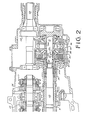
- the transfer device 20 has a front cylindrical casing 30 mounted on the output shaft 9 and a differential casing 31 connected to the front casing 30.
- a central differential 36 and a viscous coupling 40 are provided coaxially with the drive shaft 21.
- the central differential 36 comprises a pair of pinion shafts 32, each secured to the casing 31 and to a centre ring 31a which is rotatably mounted on the shaft 21, and a pair of pinion gears 33, each rotatably mounted on the pinion shaft 32.
- a differential gear 35 meshes with the pinion gears 33 and is securely mounted on the drive shaft 21, and a differential gear 34 meshes with the pinion gears 33.
- the viscous coupling 40 comprises a housing 38 having a plurality of outer disks 38a, a tubular output shaft 37b integral with the housing 38 and secured to the front drive shaft 18, a hub 39 secured to the drive shaft 21 and having a plurality of inner disks 39a, an input shaft 37a integral with the differential gear 34 and secured to the housing 38, and a high viscous fluid contained in a space defined by the hub 39, the shaft 37a and the housing 38.
- the disks are alternately arranged in the axial direction of the coupling 40.
- the viscous coupling 40 operates to generate torque in dependence on the difference.
- the torque is transmitted from a higher speed disk side to a lower speed disk side.
- a bearing 41 is disposed between the housing 38 and the drive shaft 21 for providing appropriate clearances 41a, 41b between the hub 39 and the housing 38 and between the hub 39 and the shaft 37a.
- the power of the engine 1 is transmitted to the sub transmission 4 through the clutch 2 and the drive shaft 3, and further to the main transmission 8.
- the torque of the main transmission 8 is transmitted to pinion gears 33 of the differential 36 through the output shaft 9, front casing 30, differential casing 31, and pinion shafts 32.
- the torque is transmitted to the front wheels through differential gear 34, shaft 37a, housing 38, output shaft 37b, and front drive shaft 18.
- the torque is further transmitted to the rear wheels through differential gear 35, drive shaft 21, transfer gears 22, rear drive shaft 23, propeller shaft 24 and rear differential 25.
- the present embodiment provides a system in which a viscous coupling is combined with a central differential for automatically locking the central differential.
- the viscous coupling is combined with the central differential to achieve a compact structure, so that increase of size of the transmission is prevented.
Abstract
Description
- The present invention relates to a system for transmitting the power of an engine to four driving wheels of a four-wheel drive vehicle.
- In a conventional four-wheel drive vehicle having a central differential, which is called a full time four-wheel drive vehicle, the central differential operates to uniformly distribute the torque of an engine to front wheels and to rear wheels.
- However, if one of four wheels skids, the torque is not transmitted to four wheels, so that the vehicle stops. In order to prevent such a problem, a lock mechanism for locking the central differential is provided.
- As a lock mechanism for the system, a system employing a solenoid operated dog clutch is known. Further, Japanese Patent Application Laid-Open 59-179425 discloses a system in which front wheels are connected to rear wheels by a fluid clutch or a viscous clutch. When rotational speeds of rear wheels are lower than a predetermined speed range compared with those of front wheels, the rear wheels are driven by the power for front wheel drive through a one-way clutch.
- However in the former case, since the clutch is operated by a driver in accordance with conditions of the surface of a road, it causes troublesome operations.
- In the latter system, it is difficult to determine the capacity of the viscous clutch for setting a viscous mode and a hump mode. Further, in order to obtain an appropriate operational characteristic, the viscous clutch must have a comparatively large capacity.
- The present invention seeks to provide a power system which is compact in size and automatically operates to restrict the differential operation of the central differential in accordance with driving conditions.
- According to the present invention, there is provided a power transmitting system for a four-wheel drive vehicle oomprising a transmission, a central differential having a casing, a pinion shaft secured to the casing, a pair of pinion gears mounted on the pinion shaft, and a pair of differential gears engaged with the pinion gears, and a viscous coupling having a housing and hub provided in the housing.
- The system of the present invention is characterized in that the viscous coupling is provided coaxially with the central differential, a first drive shaft is provided passing through axes of the central differential and the viscous coupling, the pinion shaft comprises a pair of shafts, an inner end of each of which is rotatably mounted on the first drive shaft, an output shaft of the transmission is operatively connected to the casing of the differential, one of the differential gears is secured to the first drive shaft, and the first drive shaft is operatively connected to either front or rear wheels, the other differential gear is secured to the housing of the viscous coupling, the housing is operatively connected to the other wheels, and the hub is secured to the first drive shaft.
- Preferably, the output shaft is a cylindrical shaft in which a second drive shaft for the other wheels is rotatably mounted, and the housing of the viscous coupling connected to the second drive shaft. The housing is preferably rotatably mounted on the first drive shaft through a bearing.
- A preferred embodiment of the invention will now be described, by way of example, with reference to the accompanying drawings, wherein:
- Figure 1 is a schematic diagram of a four-wheel drive power transmission system of the present invention;
- Figure 2 is an enlarged sectional view showing part of the system.
- Figure 1 shows a power transmission system for a four-wheel drive motor vehicle to which the present embodiment is applied. An engine 1 is longitudinally mounted on the motor vehicle at a front portion thereof, thus forming a transaxle type. The power transmission system housed in a transmission case comprises a clutch 2,
sub transmission 4, main transmission 8 andtransfer device 20. Thesub transmission 4 connected to the clutch 2 through adrive shaft 3 has a reduction gears 6 disposed between thedrive shaft 3 and an input shaft 5, and a selector mechanism 7. Thesub transmission 4 is adapted to selectively operate to directly engage thedrive shaft 3 with the input shaft 5 for providing a high speed range and to engage thedrive shaft 3 with the input shaft 5 through the reduction gears 6 for providing a low speed range. The main transmission 8 connected to the input shaft 5 has a tubular output shaft 9 parallel with the input shaft 5, five pairs of change-speed gears 10 to 14 corresponding to first to fifth speed gears,synchronizers 15 to 17, and a reverse drive gear (not shown). Afront drive shaft 18 is rotatably supported in the output shaft 9. A drive pinion 9a at the front end of theshaft 18 meshes with a crown gear of a front differential 19 so as to transmit the power to front wheels. - The
transfer device 20 is disposed behind the main transmission 8 at the rear end of the output shaft 9. Thetransfer device 20 has adrive shaft 21 disposed in alignment with thefront drive shaft 18, and is connected to arear drive shaft 23 throughtransfer gears 22. Therear drive shaft 23 is disposed in parallel with thefront drive shaft 18. Therear drive shaft 23 is connected to rear wheels through apropeller shaft 24 and arear differential 25. Accordingly, torque of the engine is distributed to front wheels and rear wheels, and the difference between rotational speeds of these wheels is absorbed. - Referring to Fig. 2, the
transfer device 20 has a frontcylindrical casing 30 mounted on the output shaft 9 and a differential casing 31 connected to thefront casing 30. In the casing 31, acentral differential 36 and a viscous coupling 40 are provided coaxially with thedrive shaft 21. - The
central differential 36 comprises a pair of pinion shafts 32, each secured to the casing 31 and to a centre ring 31a which is rotatably mounted on theshaft 21, and a pair ofpinion gears 33, each rotatably mounted on the pinion shaft 32. Adifferential gear 35 meshes with thepinion gears 33 and is securely mounted on thedrive shaft 21, and adifferential gear 34 meshes with thepinion gears 33. - The viscous coupling 40 comprises a housing 38 having a plurality of outer disks 38a, a tubular output shaft 37b integral with the housing 38 and secured to the
front drive shaft 18, ahub 39 secured to thedrive shaft 21 and having a plurality of inner disks 39a, aninput shaft 37a integral with thedifferential gear 34 and secured to the housing 38, and a high viscous fluid contained in a space defined by thehub 39, theshaft 37a and the housing 38. The disks are alternately arranged in the axial direction of the coupling 40. When there is a speed difference between the housing 38 and thehub 39, the viscous coupling 40 operates to generate torque in dependence on the difference. Thus, the torque is transmitted from a higher speed disk side to a lower speed disk side. A bearing 41 is disposed between the housing 38 and thedrive shaft 21 for providingappropriate clearances hub 39 and the housing 38 and between thehub 39 and theshaft 37a. - The power of the engine 1 is transmitted to the
sub transmission 4 through the clutch 2 and thedrive shaft 3, and further to the main transmission 8. The torque of the main transmission 8 is transmitted topinion gears 33 of thedifferential 36 through the output shaft 9,front casing 30, differential casing 31, and pinion shafts 32. At normal driving, the torque is transmitted to the front wheels throughdifferential gear 34,shaft 37a, housing 38, output shaft 37b, andfront drive shaft 18. The torque is further transmitted to the rear wheels throughdifferential gear 35,drive shaft 21,transfer gears 22,rear drive shaft 23,propeller shaft 24 andrear differential 25. - When the rear wheels skid, a speed difference between the front and rear wheels occurs. The torque of the
rear drive shaft 23 is transmitted to thedrive shaft 21. Thehub 39 secured to thedrive shaft 21 rotates faster than the housing 38. The difference of rotational speeds between outer disks 38a and inner disks 39a generates coupling torque which is transmitted to the lower speed side, namely to the outer disks 38a. Accordingly, the torque is transmitted to thedifferential gear 34, thereby preventing thepinion gears 33 from rotating. Thus, the differential operation is restricted. - This means that the
central differential 36 is automatically locked. In case of skidding of the front wheels, the central differential is locked in a similar manner to the above described operation. - From the foregoing, it will be understood that the present embodiment provides a system in which a viscous coupling is combined with a central differential for automatically locking the central differential. The viscous coupling is combined with the central differential to achieve a compact structure, so that increase of size of the transmission is prevented.
- While the presently preferred embodiment of the present invention has been shown and described, it is to be understood that this disclosure is for the purpose of illustration and that various changes and modifications may be made without departing from the scope of the invention as set forth in the appended claims.
Claims (5)
Applications Claiming Priority (2)
| Application Number | Priority Date | Filing Date | Title |
|---|---|---|---|
| JP62107268A JP2577910B2 (en) | 1987-04-30 | 1987-04-30 | Transfer device for four-wheel drive vehicles |
| JP107268/87 | 1987-04-30 |
Publications (2)
| Publication Number | Publication Date |
|---|---|
| EP0290201A1 true EP0290201A1 (en) | 1988-11-09 |
| EP0290201B1 EP0290201B1 (en) | 1991-04-17 |
Family
ID=14454749
Family Applications (1)
| Application Number | Title | Priority Date | Filing Date |
|---|---|---|---|
| EP88303861A Expired EP0290201B1 (en) | 1987-04-30 | 1988-04-28 | Power transmitting system for a four-wheel drive vehicle |
Country Status (4)
| Country | Link |
|---|---|
| US (1) | US4907472A (en) |
| EP (1) | EP0290201B1 (en) |
| JP (1) | JP2577910B2 (en) |
| DE (1) | DE3862421D1 (en) |
Families Citing this family (7)
| Publication number | Priority date | Publication date | Assignee | Title |
|---|---|---|---|---|
| US5149307A (en) * | 1991-10-15 | 1992-09-22 | General Motors Corporation | Multispeed power transmission |
| JP4104091B2 (en) * | 1996-12-13 | 2008-06-18 | 富士重工業株式会社 | Manual transmission for four-wheel drive vehicles |
| US6142905A (en) * | 1997-03-21 | 2000-11-07 | New Venture Gear, Inc. | Full-time four-wheel drive transmission with limited slip clutch |
| JP2002087091A (en) * | 2000-09-14 | 2002-03-26 | Fuji Heavy Ind Ltd | Transmission for four wheel drive vehicle |
| JP5262588B2 (en) * | 2007-12-26 | 2013-08-14 | 日産自動車株式会社 | Driving force distribution device |
| CN101925759B (en) * | 2008-01-24 | 2012-12-05 | 日产自动车株式会社 | Friction-roller type transmission mechanism |
| JP5176977B2 (en) | 2009-01-22 | 2013-04-03 | 日産自動車株式会社 | Driving force distribution device |
Citations (2)
| Publication number | Priority date | Publication date | Assignee | Title |
|---|---|---|---|---|
| GB2057987A (en) * | 1979-07-26 | 1981-04-08 | Schuler Presses Ltd | Vehicle transmission |
| US4586583A (en) * | 1983-09-19 | 1986-05-06 | Fuji Jukogyo Kabushiki Kaisha | System for controlling a power transmission of a four-wheel drive vehicle |
Family Cites Families (9)
| Publication number | Priority date | Publication date | Assignee | Title |
|---|---|---|---|---|
| US2743792A (en) * | 1951-10-11 | 1956-05-01 | Richard B Ransom | Rotary motion resisting device |
| GB1357106A (en) * | 1970-07-18 | 1974-06-19 | Ferguson Ltd Harry | Rotary couplings |
| GB1411283A (en) * | 1972-06-21 | 1975-10-22 | Gkn Transmissions Ltd | Four-wheel-drive vehicles |
| US4058027A (en) * | 1976-07-09 | 1977-11-15 | Gkn Transmissions Limited | Control couplings |
| JPS59179425A (en) * | 1983-03-28 | 1984-10-12 | Nissan Motor Co Ltd | Four-wheel-drive car |
| DE3466043D1 (en) * | 1983-06-01 | 1987-10-15 | Zahnradfabrik Friedrichshafen | Distributor gear with viscosity coupling |
| US4601359A (en) * | 1985-06-10 | 1986-07-22 | Chrysler Corporation | Part time on-demand four-wheel drive vehicle transaxle with viscous clutch |
| FR2586773B1 (en) * | 1985-09-03 | 1990-03-09 | Renault | FOUR-DRIVE TRANSMISSION DEVICE |
| FR2593754B1 (en) * | 1986-01-31 | 1990-09-07 | Renault | FOUR-DRIVE TRANSMISSION DEVICE |
-
1987
- 1987-04-30 JP JP62107268A patent/JP2577910B2/en not_active Expired - Lifetime
-
1988
- 1988-04-25 US US07/185,429 patent/US4907472A/en not_active Expired - Fee Related
- 1988-04-28 DE DE8888303861T patent/DE3862421D1/en not_active Expired - Fee Related
- 1988-04-28 EP EP88303861A patent/EP0290201B1/en not_active Expired
Patent Citations (2)
| Publication number | Priority date | Publication date | Assignee | Title |
|---|---|---|---|---|
| GB2057987A (en) * | 1979-07-26 | 1981-04-08 | Schuler Presses Ltd | Vehicle transmission |
| US4586583A (en) * | 1983-09-19 | 1986-05-06 | Fuji Jukogyo Kabushiki Kaisha | System for controlling a power transmission of a four-wheel drive vehicle |
Non-Patent Citations (1)
| Title |
|---|
| PATENT ABSTRACTS OF JAPAN, Unexamined Applications, M Field, Vol. 9, No. 38, February 19, 1985 The Patent Office Japanese Government page 70 M 358 & JP-A-59 179 425 * |
Also Published As
| Publication number | Publication date |
|---|---|
| EP0290201B1 (en) | 1991-04-17 |
| DE3862421D1 (en) | 1991-05-23 |
| JPS63270236A (en) | 1988-11-08 |
| US4907472A (en) | 1990-03-13 |
| JP2577910B2 (en) | 1997-02-05 |
Similar Documents
| Publication | Publication Date | Title |
|---|---|---|
| JP2747165B2 (en) | Differential device | |
| US4817753A (en) | Interaxle differential restriction device for vehicle four wheel drive systems | |
| US5334116A (en) | All wheel drive transfer case having two wheel overdrive | |
| US4650202A (en) | Power transmission for four-wheel drive vehicle | |
| US4982808A (en) | Viscous shear coupling | |
| JPS62137449A (en) | Transfer case | |
| EP0387053B1 (en) | Differential device for a four-wheel drive vehicle | |
| US4875978A (en) | Vehicle four wheel drive system | |
| JPS629059B2 (en) | ||
| EP0226666B1 (en) | Four-wheel vehicle drive system | |
| US4792010A (en) | Four wheel drive vehicle | |
| EP0662402A1 (en) | An electronically controlled differential with a system for controlling torque distribution | |
| GB2207983A (en) | Viscous shear coupling | |
| EP0290201B1 (en) | Power transmitting system for a four-wheel drive vehicle | |
| US5916054A (en) | Driving force distributing apparatus for four wheel drive vehicle | |
| EP0246926B1 (en) | Power transfer device for four-wheel drive | |
| EP0248577B1 (en) | Power transfer device for four-wheel drive | |
| EP0045981B1 (en) | Planetary differential | |
| US4876919A (en) | Power transfer device for four-wheel drive | |
| JPS60236839A (en) | Power transmission device for vehicle | |
| EP0274169B1 (en) | Power transmission device for a four wheel drive vehicle | |
| JP3406421B2 (en) | transmission | |
| KR100279985B1 (en) | Compound Differential Device for Four Wheel Drive Vehicle | |
| JP3075485B2 (en) | Oil pump device for vehicles | |
| EP1140544B1 (en) | Motor vehicle transmission |
Legal Events
| Date | Code | Title | Description |
|---|---|---|---|
| PUAI | Public reference made under article 153(3) epc to a published international application that has entered the european phase |
Free format text: ORIGINAL CODE: 0009012 |
|
| 17P | Request for examination filed |
Effective date: 19880506 |
|
| AK | Designated contracting states |
Kind code of ref document: A1 Designated state(s): DE GB IT SE |
|
| 17Q | First examination report despatched |
Effective date: 19900611 |
|
| GRAA | (expected) grant |
Free format text: ORIGINAL CODE: 0009210 |
|
| PGFP | Annual fee paid to national office [announced via postgrant information from national office to epo] |
Ref country code: SE Payment date: 19910408 Year of fee payment: 4 |
|
| AK | Designated contracting states |
Kind code of ref document: B1 Designated state(s): DE GB IT SE |
|
| PGFP | Annual fee paid to national office [announced via postgrant information from national office to epo] |
Ref country code: DE Payment date: 19910430 Year of fee payment: 4 |
|
| REF | Corresponds to: |
Ref document number: 3862421 Country of ref document: DE Date of ref document: 19910523 |
|
| ITF | It: translation for a ep patent filed |
Owner name: STUDIO CONS. BREVETTUALE S.R.L. |
|
| PLBE | No opposition filed within time limit |
Free format text: ORIGINAL CODE: 0009261 |
|
| STAA | Information on the status of an ep patent application or granted ep patent |
Free format text: STATUS: NO OPPOSITION FILED WITHIN TIME LIMIT |
|
| 26N | No opposition filed | ||
| PG25 | Lapsed in a contracting state [announced via postgrant information from national office to epo] |
Ref country code: GB Effective date: 19920428 |
|
| PG25 | Lapsed in a contracting state [announced via postgrant information from national office to epo] |
Ref country code: SE Effective date: 19920429 |
|
| GBPC | Gb: european patent ceased through non-payment of renewal fee | ||
| PG25 | Lapsed in a contracting state [announced via postgrant information from national office to epo] |
Ref country code: DE Effective date: 19930101 |
|
| EUG | Se: european patent has lapsed |
Ref document number: 88303861.4 Effective date: 19921108 |
|
| PG25 | Lapsed in a contracting state [announced via postgrant information from national office to epo] |
Ref country code: IT Free format text: LAPSE BECAUSE OF NON-PAYMENT OF DUE FEES;WARNING: LAPSES OF ITALIAN PATENTS WITH EFFECTIVE DATE BEFORE 2007 MAY HAVE OCCURRED AT ANY TIME BEFORE 2007. THE CORRECT EFFECTIVE DATE MAY BE DIFFERENT FROM THE ONE RECORDED. Effective date: 20050428 |