EP0289965A2 - Vorrichtung zur Änderung der Querschnittsfläche einer pneumatischen Förderleitung und Anwendung zur Einspritzung von festen Brennstoffen in einen Schachtofen - Google Patents
Vorrichtung zur Änderung der Querschnittsfläche einer pneumatischen Förderleitung und Anwendung zur Einspritzung von festen Brennstoffen in einen Schachtofen Download PDFInfo
- Publication number
- EP0289965A2 EP0289965A2 EP88106959A EP88106959A EP0289965A2 EP 0289965 A2 EP0289965 A2 EP 0289965A2 EP 88106959 A EP88106959 A EP 88106959A EP 88106959 A EP88106959 A EP 88106959A EP 0289965 A2 EP0289965 A2 EP 0289965A2
- Authority
- EP
- European Patent Office
- Prior art keywords
- section
- groove
- pipe
- cylinder
- bead
- Prior art date
- Legal status (The legal status is an assumption and is not a legal conclusion. Google has not performed a legal analysis and makes no representation as to the accuracy of the status listed.)
- Withdrawn
Links
Images


Classifications
-
- C—CHEMISTRY; METALLURGY
- C21—METALLURGY OF IRON
- C21B—MANUFACTURE OF IRON OR STEEL
- C21B5/00—Making pig-iron in the blast furnace
- C21B5/001—Injecting additional fuel or reducing agents
- C21B5/003—Injection of pulverulent coal
-
- F—MECHANICAL ENGINEERING; LIGHTING; HEATING; WEAPONS; BLASTING
- F23—COMBUSTION APPARATUS; COMBUSTION PROCESSES
- F23K—FEEDING FUEL TO COMBUSTION APPARATUS
- F23K3/00—Feeding or distributing of lump or pulverulent fuel to combustion apparatus
- F23K3/02—Pneumatic feeding arrangements, i.e. by air blast
Definitions
- the present invention relates to a device for modifying the cross section of a pneumatic transport pipe and the application of such a device to the injection of solid fuels into a tank furnace, in particular a blast furnace.
- Devices of this kind are not only used to modify the flow rate in a pneumatic conveying line, but also to provide a section with variable throttling in order to accelerate the mixture of fuels, in particular coal dust, and propulsion.
- Known devices generally comprise a slot in a mobile element which overlaps, by displacement of the latter, on a slot of a fixed element, in order to define a variable opening.
- the variation in section is very abrupt, especially in the case of small openings, which is the source of risks of obstruction and abrasion of the closed part of the passage.
- the object of the present invention is to provide a new device for modifying the cross-section of a pneumatic pulverulent material transport pipe, which allows a progressive modification, by throttling, of a section of the pipe, and in which the risk less wear and plug formation.
- the present invention provides a device for modifying the cross section of a pneumatic conveying line for pulverulent materials, which, in a first embodiment, is essentially characterized by a cylinder rotatably mounted in a block of support which is crossed tangentially with respect to the cylinder by said pipe, and in that the cylinder has, at the level of said pipe, at least a first peri-groove the depth of which varies between a minimum and a maximum which corresponds to the diameter of the pipe at the point where it is tangential to the cylinder.
- the width of the groove can be equal to the width of the pipe.
- the cylinder has a second peripheral groove which opens into the first groove and whose width is less than that of the first groove, this second groove extending from the place where the first groove reaches its depth. maximum beyond the point where this first groove ends.
- the bottom of the first and second grooves may be at a right angle or rounded, the radius of curvature then being equal to half the width of the pipe.
- the section of the pipe when passing through the block is preferably rectangular, and corresponds to the maximum section of said first groove.
- the section of the pipe is circular and the cylinder has, at this pipe, a peripheral bead whose section corresponds to half of the section of the pipe and is provided, at said bead, an elongated peripheral notch of circular section gradually increasing from a minimum to a maximum corresponding to the reverse of the section of the bead.
- the pneumatic conveying line preferably has a constriction when passing through the block.
- the device essentially comprises a cylinder 12 rotatably mounted in a support block 10, tangentially to a passage 14 connected to a pipe 16 in which is transported, pneumatically, coal into dust.
- the direction of transport is preferably from right to left.
- the section of the passage 14 is preferably smaller than that of the line 16 in order to cause, in the block 10, an acceleration of the pneumatic mixture.
- the section of the central portion of the passage 14 has a square or rectangular shape.
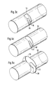
- the cylinder 12 has at least a first peripheral groove 18 which, in the position of FIG. 1, extends along a segment parallel to the vertical axis O. In a first embodiment, this groove 18 has a section such that shown in Figure 3a.
- the cylinder 12 has, in addition, a second peripheral groove 20 which extends, in the position of FIG. 1, in the third trigonometric quarter and which has the section shown in FIG. 3b, that is to say which is smaller than the groove 18.
- This groove merges, therefore, in the 180 ° position with the groove 18 and ends in the 270 ° position where the cylinder 12 is in contact with the lower wall of the passage 14. The two grooves are clearly visible in the perspective view of FIG. 3c.
- the groove 20 has a smaller section, it allows adjustment finer, i.e. for the same angle of rotation of the cylinder 12, the variation in the opening section of the passage is smaller.
- the groove 20 with a small section could constitute a handicap in the event of the formation of plugs if it is wished to clear the passage using the pressure of the propellant gas. This is the reason why the groove 18 is provided with a large section which allows rapid release by abruptly opening the passage to the maximum section.
- FIG. 4 differs from that of FIG. 3 only in that the bottom of each of the grooves 18 ′ and 20 ′ is rounded, the radius of curvature being equal to half the width of each of these grooves.
- the embodiment according to FIG. 5 is slightly different from the embodiments of Figures 3 and 4.
- the cylinder 12 is provided, on at least part of its periphery, with a bead 22 of circular section whose radius corresponds to the radius of the passage 14. This bead 22 therefore evolves in this passage 14 and obstructs it when it is there.
- the opening of the passage 14 is produced by a peripheral notch 24 (see FIG. 5) in this bead 22.
- this notch 24 relative to the outer central part of the bead 22 extends from the zero level progressively until a depth in the cylinder 12 corresponding to the thickness of the bead 22.
- the bottom of the notch 24 is circular, the radius of curvature corresponding to half its width, the opening produced by rotation of the cylinder 12 remains substantially circular, the maximum opening according to FIG. 5a having a section corresponding exactly to that of the passage 14.
Landscapes
- Engineering & Computer Science (AREA)
- Chemical & Material Sciences (AREA)
- Combustion & Propulsion (AREA)
- Mechanical Engineering (AREA)
- General Engineering & Computer Science (AREA)
- Manufacturing & Machinery (AREA)
- Materials Engineering (AREA)
- Metallurgy (AREA)
- Organic Chemistry (AREA)
- Air Transport Of Granular Materials (AREA)
- Feeding And Controlling Fuel (AREA)
- Manufacture Of Iron (AREA)
Applications Claiming Priority (2)
| Application Number | Priority Date | Filing Date | Title |
|---|---|---|---|
| LU86870 | 1987-05-07 | ||
| LU86870A LU86870A1 (fr) | 1987-05-07 | 1987-05-07 | Dispositif de modification de la section d'une conduite de transport pneumatique et application a l'injection de combustibles solides dans un four a cuve |
Publications (2)
| Publication Number | Publication Date |
|---|---|
| EP0289965A2 true EP0289965A2 (de) | 1988-11-09 |
| EP0289965A3 EP0289965A3 (de) | 1989-06-28 |
Family
ID=19730917
Family Applications (1)
| Application Number | Title | Priority Date | Filing Date |
|---|---|---|---|
| EP88106959A Withdrawn EP0289965A3 (de) | 1987-05-07 | 1988-04-30 | Vorrichtung zur Änderung der Querschnittsfläche einer pneumatischen Förderleitung und Anwendung zur Einspritzung von festen Brennstoffen in einen Schachtofen |
Country Status (6)
| Country | Link |
|---|---|
| EP (1) | EP0289965A3 (de) |
| JP (1) | JPS63311018A (de) |
| AU (1) | AU1479588A (de) |
| BR (1) | BR8802363A (de) |
| LU (1) | LU86870A1 (de) |
| ZA (1) | ZA882781B (de) |
Family Cites Families (4)
| Publication number | Priority date | Publication date | Assignee | Title |
|---|---|---|---|---|
| DE944579C (de) * | 1950-05-12 | 1956-06-21 | Steinmueller Gmbh L & C | Feuerungsanlage mit Brennstoff-Blasaufgabe |
| FR2098715A5 (de) * | 1970-07-24 | 1972-03-10 | Demurger & Cie Ets | |
| AU6073680A (en) * | 1979-08-09 | 1981-02-12 | Bougainville Copper Ltd. | Adjustable flow plug valve |
| AU557972B2 (en) * | 1982-11-10 | 1987-01-15 | Paul Wurth S.A. | Device to introduce dosed quantities of pulverulent substances into a pneumatic propulsion fluid and use to inject solid fuels into a furnace |
-
1987
- 1987-05-07 LU LU86870A patent/LU86870A1/fr unknown
-
1988
- 1988-04-20 AU AU14795/88A patent/AU1479588A/en not_active Abandoned
- 1988-04-20 ZA ZA882781A patent/ZA882781B/xx unknown
- 1988-04-30 EP EP88106959A patent/EP0289965A3/de not_active Withdrawn
- 1988-05-02 JP JP63109868A patent/JPS63311018A/ja active Pending
- 1988-05-06 BR BR8802363A patent/BR8802363A/pt unknown
Also Published As
| Publication number | Publication date |
|---|---|
| ZA882781B (en) | 1988-10-20 |
| JPS63311018A (ja) | 1988-12-19 |
| AU1479588A (en) | 1988-11-10 |
| LU86870A1 (fr) | 1989-01-19 |
| BR8802363A (pt) | 1988-12-13 |
| EP0289965A3 (de) | 1989-06-28 |
Similar Documents
| Publication | Publication Date | Title |
|---|---|---|
| FR2613448A1 (fr) | Mecanisme a engrenages a axes perpendiculaires | |
| FR2833902A1 (fr) | Phare a reflecteur mobile pour vehicule | |
| FR2677909A1 (fr) | Machine-outil, en particulier scie a moteur a chaine. | |
| FR2798452A1 (fr) | Lampe pour vehicule et dispositif de deplacement par pivotement d'un reflecteur de lampe | |
| EP0070766B1 (de) | Gelenkbolzen zur Verbindung zweier Teile | |
| FR2868738A1 (fr) | Embout pour tubulure de remplissage en carburant d'un vehicule | |
| FR2673744A1 (fr) | Dispositif de guidage de pieces de monnaie. | |
| EP0289965A2 (de) | Vorrichtung zur Änderung der Querschnittsfläche einer pneumatischen Förderleitung und Anwendung zur Einspritzung von festen Brennstoffen in einen Schachtofen | |
| FR2534345A1 (fr) | Commande de debit pour interface par clapet | |
| EP0597764B1 (de) | Fensterheber für ein Kraftfahrzeug | |
| EP0723065B1 (de) | Rolladen ausgeführt mit Kastendurchführung | |
| EP0970302A1 (de) | Steuervorrichtung zum öffnen und schliessen von mindestens einer luftzufuhrleitung eines zylinderkopfes einer brennkraftmaschine | |
| EP0451895B1 (de) | Rollenantriebsvorrichtung an einer Webmaschine | |
| FR2682164A1 (fr) | Installation de pompage de gaz avec regulation de la vitesse de pompage. | |
| FR2598127A1 (fr) | Dispositif de reglage de l'orientation du reflecteur d'un projecteur de vehicule automobile | |
| FR2831496A1 (fr) | Siege pour vehicule automobile avec tablette articulee | |
| CA1254757A (fr) | Dispositif d'accouplement a denture pour arbres oscillants | |
| FR2636106A1 (fr) | Dispositif de commande par cable en particulier pour derailleur de bicyclette | |
| FR2834529A1 (fr) | Automatisme d'ouverture et de fermeture de battant de porte, de portail ou similaire et porte, portail ou similaire equipe d'un tel automatisme | |
| FR2479112A1 (fr) | Dispositif de reglage de l'ecartement d'une zone d'un ensemble tel qu'un projecteur par rapport a une zone d'un autre ensemble tel que la carrosserie d'un vehicule | |
| FR2842463A1 (fr) | Aerateur pour vehicule automobile a debit d'air reglable et flux orientable, et vehicule equipe d'un tel aerateur | |
| FR2686835A1 (fr) | Dispositif de deroulement controle et d'enroulement automatique d'un cable ou analogue. | |
| EP0175164A1 (de) | Vorrichtung um die axiale Position eines auf einer werkzeugmaschine zu bearbeitenden Werkstückes zu messen, insbesondere auf einer Schleifmaschine für äussere zylindrische Flächen | |
| EP0524105B1 (de) | Nichtabmontierbares Zwischenstück, insbesondere zum Einstellen der Orientierung von Fahrzeugscheinwerfern | |
| EP0233624A2 (de) | Dosiereinrichtung für feinkörnige Feststoffe und Anwendung für ein dosiertes Einblasen von festen Brennstoffen in einen Schachtofen |
Legal Events
| Date | Code | Title | Description |
|---|---|---|---|
| PUAI | Public reference made under article 153(3) epc to a published international application that has entered the european phase |
Free format text: ORIGINAL CODE: 0009012 |
|
| AK | Designated contracting states |
Kind code of ref document: A2 Designated state(s): BE DE ES FR GB IT |
|
| PUAL | Search report despatched |
Free format text: ORIGINAL CODE: 0009013 |
|
| AK | Designated contracting states |
Kind code of ref document: A3 Designated state(s): BE DE ES FR GB IT |
|
| 17P | Request for examination filed |
Effective date: 19891106 |
|
| 17Q | First examination report despatched |
Effective date: 19900314 |
|
| STAA | Information on the status of an ep patent application or granted ep patent |
Free format text: STATUS: THE APPLICATION IS DEEMED TO BE WITHDRAWN |
|
| 18D | Application deemed to be withdrawn |
Effective date: 19900725 |