EP0288288A2 - I-T-H pipe cutting tool - Google Patents
I-T-H pipe cutting tool Download PDFInfo
- Publication number
- EP0288288A2 EP0288288A2 EP88303624A EP88303624A EP0288288A2 EP 0288288 A2 EP0288288 A2 EP 0288288A2 EP 88303624 A EP88303624 A EP 88303624A EP 88303624 A EP88303624 A EP 88303624A EP 0288288 A2 EP0288288 A2 EP 0288288A2
- Authority
- EP
- European Patent Office
- Prior art keywords
- rotary apparatus
- pipe
- tool according
- rotary
- tool
- Prior art date
- Legal status (The legal status is an assumption and is not a legal conclusion. Google has not performed a legal analysis and makes no representation as to the accuracy of the status listed.)
- Granted
Links
Images
Classifications
-
- B—PERFORMING OPERATIONS; TRANSPORTING
- B23—MACHINE TOOLS; METAL-WORKING NOT OTHERWISE PROVIDED FOR
- B23D—PLANING; SLOTTING; SHEARING; BROACHING; SAWING; FILING; SCRAPING; LIKE OPERATIONS FOR WORKING METAL BY REMOVING MATERIAL, NOT OTHERWISE PROVIDED FOR
- B23D45/00—Sawing machines or sawing devices with circular saw blades or with friction saw discs
- B23D45/12—Sawing machines or sawing devices with circular saw blades or with friction saw discs with a circular saw blade for cutting tubes
- B23D45/128—Sawing machines or sawing devices with circular saw blades or with friction saw discs with a circular saw blade for cutting tubes with the tool introduced into the tubes and cutting from the inside outwards
-
- E—FIXED CONSTRUCTIONS
- E21—EARTH OR ROCK DRILLING; MINING
- E21B—EARTH OR ROCK DRILLING; OBTAINING OIL, GAS, WATER, SOLUBLE OR MELTABLE MATERIALS OR A SLURRY OF MINERALS FROM WELLS
- E21B29/00—Cutting or destroying pipes, packers, plugs or wire lines, located in boreholes or wells, e.g. cutting of damaged pipes, of windows; Deforming of pipes in boreholes or wells; Reconditioning of well casings while in the ground
-
- Y—GENERAL TAGGING OF NEW TECHNOLOGICAL DEVELOPMENTS; GENERAL TAGGING OF CROSS-SECTIONAL TECHNOLOGIES SPANNING OVER SEVERAL SECTIONS OF THE IPC; TECHNICAL SUBJECTS COVERED BY FORMER USPC CROSS-REFERENCE ART COLLECTIONS [XRACs] AND DIGESTS
- Y10—TECHNICAL SUBJECTS COVERED BY FORMER USPC
- Y10T—TECHNICAL SUBJECTS COVERED BY FORMER US CLASSIFICATION
- Y10T83/00—Cutting
- Y10T83/384—By tool inside hollow work
- Y10T83/391—With means to position tool[s] for cutting
-
- Y—GENERAL TAGGING OF NEW TECHNOLOGICAL DEVELOPMENTS; GENERAL TAGGING OF CROSS-SECTIONAL TECHNOLOGIES SPANNING OVER SEVERAL SECTIONS OF THE IPC; TECHNICAL SUBJECTS COVERED BY FORMER USPC CROSS-REFERENCE ART COLLECTIONS [XRACs] AND DIGESTS
- Y10—TECHNICAL SUBJECTS COVERED BY FORMER USPC
- Y10T—TECHNICAL SUBJECTS COVERED BY FORMER US CLASSIFICATION
- Y10T83/00—Cutting
- Y10T83/384—By tool inside hollow work
- Y10T83/394—One tool having unidirectional rotary motion
-
- Y—GENERAL TAGGING OF NEW TECHNOLOGICAL DEVELOPMENTS; GENERAL TAGGING OF CROSS-SECTIONAL TECHNOLOGIES SPANNING OVER SEVERAL SECTIONS OF THE IPC; TECHNICAL SUBJECTS COVERED BY FORMER USPC CROSS-REFERENCE ART COLLECTIONS [XRACs] AND DIGESTS
- Y10—TECHNICAL SUBJECTS COVERED BY FORMER USPC
- Y10T—TECHNICAL SUBJECTS COVERED BY FORMER US CLASSIFICATION
- Y10T83/00—Cutting
- Y10T83/929—Tool or tool with support
- Y10T83/9372—Rotatable type
- Y10T83/9403—Disc type
Definitions
- the instant invention relates to drilling in general and more particularly to an apparatus adapted to retrieve valuable in-the-hole ("I-T-H") drill string components otherwise normally left abandoned in a hole.
- I-T-H in-the-hole
- I-T-H drill string components (usually pipe) are frequently damaged and, as a consequence, become stuck in the drill hole.
- considerable economic losses may be experienced when the entire drill string cannot be retrieved simply because a small portion has become stuck. It is difficult and sometimes impossible to uncouple drill pipe joints above the damaged section at any appreciable depth. Assignee looses several $100,000 a year in abandoned but otherwise good drill pipe.
- a remotely operated compact cutting tool adapted for deep insertion into I-T-H drill rod.
- the tool having a hinged rotary motor and associated cutting disc is fed into the pipe string to a predetermined depth at which point the motor is activated and pitched toward the interior surface of the pipe.
- the cutting disc proceeds to cut the pipe and permits the removal thereof.
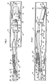
- Figure 1 depicts the tool 10 as it is being inserted into the drill string 12 whereas Figure 2 shows the tool 10 after pipe 14, comprising a portion of the drill string 12, has been cut.
- the drill string 12 includes pipes 14 and 16.
- Depression 22 represents a wrenching slot. Assume for the ensuing discussion that a portion of the drill string 12 is damaged downstream the pipe 14 and it is necessary to cut the pipe 14 in order to free the remaining upstream undamaged portions of the drill string.
- the cutter 10 is preferably pneumatically driven to take advantage of the commonly available pneumatic sources of supply that are ubiquitous in surface and underground excavations.
- the cutter 10 includes a high speed motor 24 of relatively small dimension.
- a Cleco (trademark) pencil grinder model 15GEL180WC rotates up to about 18,000 revolutions per minute, operates up to 90 pounds per square inch gauge (621 kPa), and generates about 1.0 horsepower (746 watts).
- Attached to the hub 62 of the motor 24 is a cutting disc 26, preferably made from Carborundum (trademark) abrasive or any similar material suitable for cutting metal pipe.
- the motor 24 is enclosed in an open box frame 28 formed by two parallel side brackets 30 (only one is shown).
- Reference numeral 64 represents the axis of symmetry of both the tool 10 and the drill string 12.
- the motor 24 is pivotally mounted at the distal portion of the frame 28 via collar 32.
- the collar 32 is designed to rotate through arc 34 about pivot 36.
- the proximal section of the box frame 28 is formed by second collar 38.
- a stop 58 extends from the box frame 28.
- Pneumatic power is supplied to the tool 10 from a conventional source (not shown) at dividing connection 40.
- High pressure air enters the connection 40 at entrance port 42 and is divided internally into two paths to flow out of exit ports 44 and 46.
- the exit port 46 supplies, via conduit 48, air pressure to the motor 24.
- Air exiting the exit port 44 is fed into cylinder 50 by conduit 52.
- the cylinder 50 includes a piston 54, registered to activator 56.
- the activator 56 is attached to the rear of the motor 24 and, in the embodiment shown, has a slight bend.
- the piston 54 may be canted slightly away from the axis of symmetry 64 to accommodate the bend in the activator 56.
- a frusto-conical centralizer 60 releasably affixed to the hub 62 of the motor 24, permits the tool 10 to be fished down the drill string 12 through the various unions to a predetermined depth.
- the tool 10 Upon the determination that a portion of the drill string is damaged and it is desired to remove the string components above the damaged section, the tool 10 is inserted into the string until the cutting disc 26 reaches the desired depth.
- the centralizer 60 is affixed to the hub 62 so as to allow the tool to pass through the couplings in the string.
- the frusto-conical shape of the centralizer 60 Upon hitting an obstruction, the frusto-conical shape of the centralizer 60 will cause the motor 24 to slightly pivot out of the way of the obstruction and continue to guide the tool 10 to the desired location.
- the centralizer 60 is securely, but not permanently, affixed to the hub 62 so that upon activation of the motor 24, the rotation of the hub 62 will throw off the expendable centralizer 60 into the pipe 14.
- Figure 1 shows the tool 10 essentially in a neutral or straight position for passage through the string 12 components.
- a relatively rigid air supply conduit (not shown) communicating with a pneumatic supply source such as a pump and control valve is connected to the entrance port 42.
- a pneumatic supply source such as a pump and control valve
- pressurized air is introduced into the connection 40. Air passing through the conduit 48 will activate the motor 24 causing the cutting disc 26 to rotate and the disposal of the centralizer 60. Simultaneously, the air passing into the cylinder 50 via conduit 52 will cause the piston 54 to extend thereby pushing the activator 56. By virtue of the curved geometry of the activator 56, the motor 24 is caused to rotate about the pivot 36 through the arc 34 and bring the cutting disc 26 into contact with the pipe 14. As long as the pressurized air is supplied to the tool 10, the motor 24 will assume the cutting position against the pipe 14. See Figure 2. Simultaneously, the tool 10 is slowly rotated 68 by means, not shown, about the axis of symmetry 64 to allow the cutting disc 26 to travel about the interior diameter of the pipe 14.
- initiation or deletion of the air supply to the components may be likened to a signal as well as a source of power. That is, when the air supply is turned on, the air will signal the motor 24 and piston 54 to initiate movement.
- the air pressure source is shut off. Due to weight and the mounted bias orientation of the motor 24 within the box frame 28, the motor 24 will essentially return to its neutral, straight position coincident with the axis of symmetry 64 within the pipe 14 so as to enable it to be removed without any difficulty.
- the stop 58 prevents the tool 10 from pivoting too extensively in the opposite direction.
- a spring (not shown) may be employed to bias the motor 24 in the neutral, straight position.
- pressurized air is the preferable power supply
- the tool 10 may be alternatively powered and signalled by electrical or hydraulic means.
- an electrical or hydraulic motor may be utilized.
- the air cylinder 50 may be replaced with a hydraulic cylinder or electrical servomotor and the appropriate controls.
- pneumatic power is preferred since it is relatively easy to harness and supply.
- the remainder of the drill string 12 may be removed by conventional means and methods, such as a jack, etc.
Landscapes
- Engineering & Computer Science (AREA)
- Geology (AREA)
- Life Sciences & Earth Sciences (AREA)
- Mining & Mineral Resources (AREA)
- Environmental & Geological Engineering (AREA)
- Fluid Mechanics (AREA)
- Physics & Mathematics (AREA)
- General Life Sciences & Earth Sciences (AREA)
- Geochemistry & Mineralogy (AREA)
- Mechanical Engineering (AREA)
- Earth Drilling (AREA)
- Surgical Instruments (AREA)
- Sawing (AREA)
Abstract
Description
- The instant invention relates to drilling in general and more particularly to an apparatus adapted to retrieve valuable in-the-hole ("I-T-H") drill string components otherwise normally left abandoned in a hole.
- As a result of blasting operations, I-T-H drill string components (usually pipe) are frequently damaged and, as a consequence, become stuck in the drill hole. Depending on the length of the pipe, considerable economic losses may be experienced when the entire drill string cannot be retrieved simply because a small portion has become stuck. It is difficult and sometimes impossible to uncouple drill pipe joints above the damaged section at any appreciable depth. Assignee looses several $100,000 a year in abandoned but otherwise good drill pipe.
- There have been attempts to wrestle with this problem. Pipe cutters and perforators of various descriptions have been devised. Principally, a cutter of some description is utilized. Although perhaps effective for conventional pipe cutting operations and on the surface, they are unwieldily when applied to I-T-H pipe and inapplicable at great depths.
- Representative designs may be found in U.S. Patents 514,985; 669,983; 1,088,135; 4,220,201; 4,307,512; 4,527,511; 4,574,672; German Auslegeschrift 1,136,956; German Patentschrift 342,498 and Russian 605,934.
- Clearly an apparatus especially addressed to the unique demands of the retrieval of non-damaged I-T-H pipe is desirable.
- Accordingly, there is provided a remotely operated compact cutting tool adapted for deep insertion into I-T-H drill rod. The tool having a hinged rotary motor and associated cutting disc is fed into the pipe string to a predetermined depth at which point the motor is activated and pitched toward the interior surface of the pipe. The cutting disc proceeds to cut the pipe and permits the removal thereof.
-
- Figure 1 is an elevation of an embodiment of the invention in partial cross section.
- Figure 2 is similar to the view shown in Figure 1.
- Referring to Figure 1 and Figure 2, there is shown
pipe cutting tool 10 disposed within anI-T-H drill string 12. Although the ensuing discussion relates primarily to drilling applications, it will be appreciated that the instant invention may be utilized for other tube cutting applications as well. - Figure 1 depicts the
tool 10 as it is being inserted into thedrill string 12 whereas Figure 2 shows thetool 10 afterpipe 14, comprising a portion of thedrill string 12, has been cut. - The
drill string 12, as depicted, includespipes pin end 18 threadably engagingbox end 20.Depression 22 represents a wrenching slot. Assume for the ensuing discussion that a portion of thedrill string 12 is damaged downstream thepipe 14 and it is necessary to cut thepipe 14 in order to free the remaining upstream undamaged portions of the drill string. - The
cutter 10 is preferably pneumatically driven to take advantage of the commonly available pneumatic sources of supply that are ubiquitous in surface and underground excavations. Thecutter 10 includes ahigh speed motor 24 of relatively small dimension. Favorable results have been experienced with a Cleco (trademark) pencil grinder model 15GEL180WC. It rotates up to about 18,000 revolutions per minute, operates up to 90 pounds per square inch gauge (621 kPa), and generates about 1.0 horsepower (746 watts). Attached to thehub 62 of themotor 24 is acutting disc 26, preferably made from Carborundum (trademark) abrasive or any similar material suitable for cutting metal pipe. - The
motor 24 is enclosed in anopen box frame 28 formed by two parallel side brackets 30 (only one is shown).Reference numeral 64 represents the axis of symmetry of both thetool 10 and thedrill string 12. Themotor 24 is pivotally mounted at the distal portion of theframe 28 viacollar 32. Thecollar 32 is designed to rotate througharc 34 aboutpivot 36. The proximal section of thebox frame 28 is formed bysecond collar 38. Astop 58 extends from thebox frame 28. - Pneumatic power is supplied to the
tool 10 from a conventional source (not shown) at dividingconnection 40. High pressure air enters theconnection 40 atentrance port 42 and is divided internally into two paths to flow out ofexit ports exit port 46 supplies, viaconduit 48, air pressure to themotor 24. - Air exiting the
exit port 44 is fed intocylinder 50 byconduit 52. Thecylinder 50 includes apiston 54, registered toactivator 56. Theactivator 56 is attached to the rear of themotor 24 and, in the embodiment shown, has a slight bend. Thepiston 54 may be canted slightly away from the axis ofsymmetry 64 to accommodate the bend in theactivator 56. - A frusto-
conical centralizer 60, releasably affixed to thehub 62 of themotor 24, permits thetool 10 to be fished down thedrill string 12 through the various unions to a predetermined depth. - The invention and manner of applying it may be better understood by a brief discussion of the principles underlying the invention.
- Upon the determination that a portion of the drill string is damaged and it is desired to remove the string components above the damaged section, the
tool 10 is inserted into the string until thecutting disc 26 reaches the desired depth. Initially, thecentralizer 60 is affixed to thehub 62 so as to allow the tool to pass through the couplings in the string. Upon hitting an obstruction, the frusto-conical shape of thecentralizer 60 will cause themotor 24 to slightly pivot out of the way of the obstruction and continue to guide thetool 10 to the desired location. Thecentralizer 60 is securely, but not permanently, affixed to thehub 62 so that upon activation of themotor 24, the rotation of thehub 62 will throw off theexpendable centralizer 60 into thepipe 14. - Figure 1 shows the
tool 10 essentially in a neutral or straight position for passage through thestring 12 components. A relatively rigid air supply conduit (not shown) communicating with a pneumatic supply source such as a pump and control valve is connected to theentrance port 42. The combination of the rigidity of the air supply and the centering action of thecentralizer 60 permit thetool 10 to be guided to the desired depth. - For the sake of convenience, movement to the right in the Figures indicates greater bore depth whereas movement to the left indicates closer proximity to the surface.
- Upon attainment of the desired depth, pressurized air is introduced into the
connection 40. Air passing through theconduit 48 will activate themotor 24 causing thecutting disc 26 to rotate and the disposal of thecentralizer 60. Simultaneously, the air passing into thecylinder 50 viaconduit 52 will cause thepiston 54 to extend thereby pushing theactivator 56. By virtue of the curved geometry of theactivator 56, themotor 24 is caused to rotate about thepivot 36 through thearc 34 and bring thecutting disc 26 into contact with thepipe 14. As long as the pressurized air is supplied to thetool 10, themotor 24 will assume the cutting position against thepipe 14. See Figure 2. Simultaneously, thetool 10 is slowly rotated 68 by means, not shown, about the axis ofsymmetry 64 to allow thecutting disc 26 to travel about the interior diameter of thepipe 14. - In a sense, initiation or deletion of the air supply to the components may be likened to a signal as well as a source of power. That is, when the air supply is turned on, the air will signal the
motor 24 andpiston 54 to initiate movement. - After the
pipe 14 has been cut alongline 66, the air pressure source is shut off. Due to weight and the mounted bias orientation of themotor 24 within thebox frame 28, themotor 24 will essentially return to its neutral, straight position coincident with the axis ofsymmetry 64 within thepipe 14 so as to enable it to be removed without any difficulty. Thestop 58 prevents thetool 10 from pivoting too extensively in the opposite direction. In the event that thetool 10 is utilized in a direction other than down, a spring (not shown) may be employed to bias themotor 24 in the neutral, straight position. - Although pressurized air is the preferable power supply, it shall be apparent that the
tool 10 may be alternatively powered and signalled by electrical or hydraulic means. Instead of theair motor 24, an electrical or hydraulic motor may be utilized. Similarly, theair cylinder 50 may be replaced with a hydraulic cylinder or electrical servomotor and the appropriate controls. However, for most applications and especially for I-T-H applications, pneumatic power is preferred since it is relatively easy to harness and supply. - In any event, after the
pipe 14 is cut above the damaged section, the remainder of thedrill string 12 may be removed by conventional means and methods, such as a jack, etc. - Prototype designs incorporating the instant invention have helped retrieve about $182,000 of I-T-H drill pipe annually. This represents a large cost savings and the retrieval of an otherwise wasted resource.
Claims (11)
Applications Claiming Priority (2)
| Application Number | Priority Date | Filing Date | Title |
|---|---|---|---|
| CA 535380 CA1284459C (en) | 1987-04-23 | 1987-04-23 | I-t-h pipe cutting tool |
| CA535380 | 1987-04-23 |
Publications (3)
| Publication Number | Publication Date |
|---|---|
| EP0288288A2 true EP0288288A2 (en) | 1988-10-26 |
| EP0288288A3 EP0288288A3 (en) | 1989-07-19 |
| EP0288288B1 EP0288288B1 (en) | 1992-03-04 |
Family
ID=4135483
Family Applications (1)
| Application Number | Title | Priority Date | Filing Date |
|---|---|---|---|
| EP19880303624 Expired - Lifetime EP0288288B1 (en) | 1987-04-23 | 1988-04-21 | I-t-h pipe cutting tool |
Country Status (11)
| Country | Link |
|---|---|
| US (1) | US4809775A (en) |
| EP (1) | EP0288288B1 (en) |
| JP (1) | JPS63283812A (en) |
| AU (1) | AU598661B2 (en) |
| BR (1) | BR8801873A (en) |
| CA (1) | CA1284459C (en) |
| DE (1) | DE3868675D1 (en) |
| ES (1) | ES2029882T3 (en) |
| FI (1) | FI88743C (en) |
| GR (1) | GR3004304T3 (en) |
| NZ (1) | NZ224318A (en) |
Cited By (3)
| Publication number | Priority date | Publication date | Assignee | Title |
|---|---|---|---|---|
| RU2381860C1 (en) * | 2008-09-15 | 2010-02-20 | Федеральное государственное унитарное предприятие "Российский Федеральный ядерный центр - Всероссийский научно-исследовательский институт экспериментальной физики" - ФГУП "РФЯЦ-ВНИИЭФ" | Device to cut wire bunches |
| EP2329903A1 (en) * | 2009-12-04 | 2011-06-08 | AuTech GmbH | Tube cutting method and device |
| WO2017153168A3 (en) * | 2016-03-07 | 2017-10-19 | Metpetra B.V. | Tubular cutting device |
Families Citing this family (14)
| Publication number | Priority date | Publication date | Assignee | Title |
|---|---|---|---|---|
| US5431220A (en) * | 1994-03-24 | 1995-07-11 | Smith International, Inc. | Whipstock starter mill assembly |
| USD400075S (en) | 1997-05-19 | 1998-10-27 | Grinnell Corp. | Pipe cutting tool |
| US6629565B2 (en) | 2000-07-24 | 2003-10-07 | Smith International, Inc. | Abandonment and retrieval apparatus and method |
| US6626074B1 (en) | 2002-05-14 | 2003-09-30 | Theodore D. Wheeler | Down hole pipe and casing cutter |
| GB0226725D0 (en) * | 2002-11-15 | 2002-12-24 | Bp Exploration Operating | method |
| US7644763B2 (en) * | 2007-03-26 | 2010-01-12 | Baker Hughes Incorporated | Downhole cutting tool and method |
| US7574807B1 (en) * | 2007-04-19 | 2009-08-18 | Holelocking Enterprises Llc | Internal pipe cutter |
| US7823632B2 (en) * | 2008-06-14 | 2010-11-02 | Completion Technologies, Inc. | Method and apparatus for programmable robotic rotary mill cutting of multiple nested tubulars |
| US9759030B2 (en) | 2008-06-14 | 2017-09-12 | Tetra Applied Technologies, Llc | Method and apparatus for controlled or programmable cutting of multiple nested tubulars |
| US9410390B2 (en) * | 2010-08-24 | 2016-08-09 | Stanislav Tolstihin | Device for drilling through a formation |
| US20140000428A1 (en) * | 2012-06-29 | 2014-01-02 | Baker Hughes Incorporated | Self-Lubricating Saw Blade Assembly with Debris Removal Paths |
| MY183463A (en) | 2014-07-14 | 2021-02-18 | Aarbakke Innovation A S | Wellbore intervention tool for penetrating obstructions in a wellbore |
| KR101957956B1 (en) * | 2016-05-31 | 2019-03-14 | (주)엠알이노베이션 | Injection equipment for manufacture of needleless injection syringe |
| CN106825735B (en) * | 2017-03-14 | 2019-03-19 | 湖北正浩建设集团有限公司 | A kind of cutting method of pipe laying cutting machine |
Family Cites Families (17)
| Publication number | Priority date | Publication date | Assignee | Title |
|---|---|---|---|---|
| US514985A (en) * | 1894-02-20 | Boiler-flue cutter | ||
| DE342498C (en) * | ||||
| US669983A (en) * | 1900-06-30 | 1901-03-19 | Otto H Ewest | Pipe-cutting tool. |
| US1088135A (en) * | 1911-11-13 | 1914-02-24 | Robert Thomas Fagan | Welll-saw. |
| US1392192A (en) * | 1920-06-22 | 1921-09-27 | George W Miller | Pipe-cutter |
| US2534858A (en) * | 1946-06-08 | 1950-12-19 | Guy P Ellis | Pipe cutter |
| US2942092A (en) * | 1959-02-27 | 1960-06-21 | Fred W Cammann | Internal tube cutter |
| DE1136956B (en) * | 1960-03-10 | 1962-09-27 | Rheinische Braunkohlenw Ag | Device for cutting well pipes, in particular for dewatering a coal field |
| FR1465588A (en) * | 1965-11-30 | 1967-01-13 | Commissariat Energie Atomique | Machine for machining the inner surface of a tube |
| SU605934A1 (en) * | 1973-09-26 | 1978-05-05 | Leonov Mikhail D | Device for cutting pipes in well |
| US4106561A (en) * | 1977-05-12 | 1978-08-15 | Jerome Robert J | Well casing perforator |
| US4220201A (en) * | 1979-02-21 | 1980-09-02 | Service Equipment Design Co., Inc. | Casing perforator |
| US4307512A (en) * | 1980-08-20 | 1981-12-29 | Phillips Herbert H | Rotary wand with attached circular saw blade |
| US4524511A (en) * | 1983-02-28 | 1985-06-25 | Remcut International Inc. | Adjustable interior pipe cutter |
| DE3341424C2 (en) * | 1983-11-14 | 1986-03-13 | Tremag Trennmaschinen-Gesellschaft mbH, 4100 Duisburg | Drive device |
| GB8407707D0 (en) * | 1984-03-24 | 1984-05-02 | Edgealpha Ltd | Cutters |
| US4601223A (en) * | 1984-07-16 | 1986-07-22 | Westinghouse Electric Corp. | Flail tube cutter |
-
1987
- 1987-04-23 CA CA 535380 patent/CA1284459C/en not_active Expired - Fee Related
-
1988
- 1988-04-04 US US07/177,432 patent/US4809775A/en not_active Expired - Fee Related
- 1988-04-20 BR BR8801873A patent/BR8801873A/en not_active IP Right Cessation
- 1988-04-21 NZ NZ22431888A patent/NZ224318A/en unknown
- 1988-04-21 DE DE8888303624T patent/DE3868675D1/en not_active Expired - Fee Related
- 1988-04-21 EP EP19880303624 patent/EP0288288B1/en not_active Expired - Lifetime
- 1988-04-21 ES ES88303624T patent/ES2029882T3/en not_active Expired - Lifetime
- 1988-04-21 AU AU15044/88A patent/AU598661B2/en not_active Ceased
- 1988-04-22 JP JP63100020A patent/JPS63283812A/en active Granted
- 1988-04-22 FI FI881895A patent/FI88743C/en not_active IP Right Cessation
-
1992
- 1992-04-08 GR GR920400666T patent/GR3004304T3/el unknown
Cited By (5)
| Publication number | Priority date | Publication date | Assignee | Title |
|---|---|---|---|---|
| RU2381860C1 (en) * | 2008-09-15 | 2010-02-20 | Федеральное государственное унитарное предприятие "Российский Федеральный ядерный центр - Всероссийский научно-исследовательский институт экспериментальной физики" - ФГУП "РФЯЦ-ВНИИЭФ" | Device to cut wire bunches |
| EP2329903A1 (en) * | 2009-12-04 | 2011-06-08 | AuTech GmbH | Tube cutting method and device |
| WO2017153168A3 (en) * | 2016-03-07 | 2017-10-19 | Metpetra B.V. | Tubular cutting device |
| CN109196182A (en) * | 2016-03-07 | 2019-01-11 | Yta有限责任公司 | Pipe cutting device |
| CN109196182B (en) * | 2016-03-07 | 2022-03-18 | Yta有限责任公司 | Pipe fitting cutting device |
Also Published As
| Publication number | Publication date |
|---|---|
| AU1504488A (en) | 1988-10-27 |
| FI881895L (en) | 1988-10-24 |
| AU598661B2 (en) | 1990-06-28 |
| FI881895A0 (en) | 1988-04-22 |
| DE3868675D1 (en) | 1992-04-09 |
| JPS63283812A (en) | 1988-11-21 |
| FI88743C (en) | 1993-06-28 |
| FI88743B (en) | 1993-03-15 |
| EP0288288B1 (en) | 1992-03-04 |
| ES2029882T3 (en) | 1992-10-01 |
| CA1284459C (en) | 1991-05-28 |
| JPH0478406B2 (en) | 1992-12-11 |
| NZ224318A (en) | 1990-05-28 |
| US4809775A (en) | 1989-03-07 |
| BR8801873A (en) | 1989-11-14 |
| EP0288288A3 (en) | 1989-07-19 |
| GR3004304T3 (en) | 1993-03-31 |
Similar Documents
| Publication | Publication Date | Title |
|---|---|---|
| US4809775A (en) | I-T-H pipe cutting tool | |
| EP1957751B1 (en) | Downhole hydraulic pipe cutter | |
| CA2007461C (en) | Whipstock starter mill with pressure drop tattletale | |
| JP2000505165A (en) | Directional bowling | |
| JPH0363392A (en) | Replacement of existing pipe to new one, and its apparatus | |
| CA1310457C (en) | Cutting and the like tools | |
| CA2399912A1 (en) | Extender assembly for core drill | |
| US4896733A (en) | Technique for providing an underground tunnel utilizing a powered boring device | |
| WO2002070175A2 (en) | Core drill piloting system | |
| US6283229B1 (en) | Impact device for directional boring | |
| GB2139938A (en) | Improvements in or relating to methods and apparatus for pipe replacement and boring | |
| WO1989010467A1 (en) | Method and apparatus for the production of underground pipelines | |
| EP0485052A1 (en) | Boring head and method for directional drilling in the ground | |
| WO2016093705A1 (en) | Cutting unit for internal cutting of tubing | |
| JPH01231980A (en) | Pig for working inside pipes | |
| US4248559A (en) | Controlled depth scoring system | |
| US3106257A (en) | Rock core drills | |
| EP0063940A2 (en) | Cutting method and apparatus | |
| EP0504120A1 (en) | Method and apparatus for subsoil drilling | |
| US6709315B1 (en) | Auto feed system for compressed propellant tools and pressure compensating valve therefore | |
| JPS6187020A (en) | Steel pipe sheet pile cutting equipment | |
| JPS6322208A (en) | Boring device for hot spring pipe | |
| EP0207576B1 (en) | Apparatus for determining the positioning and measuring the depth, on which a construction or object is positioned in the ground | |
| US11376641B2 (en) | Method and apparatus for seam dressing | |
| US2627654A (en) | Mining drill bit extractor |
Legal Events
| Date | Code | Title | Description |
|---|---|---|---|
| PUAI | Public reference made under article 153(3) epc to a published international application that has entered the european phase |
Free format text: ORIGINAL CODE: 0009012 |
|
| AK | Designated contracting states |
Kind code of ref document: A2 Designated state(s): CH DE ES FR GB GR IT LI SE |
|
| PUAL | Search report despatched |
Free format text: ORIGINAL CODE: 0009013 |
|
| AK | Designated contracting states |
Kind code of ref document: A3 Designated state(s): CH DE ES FR GB GR IT LI SE |
|
| 17P | Request for examination filed |
Effective date: 19900116 |
|
| 17Q | First examination report despatched |
Effective date: 19901221 |
|
| GRAA | (expected) grant |
Free format text: ORIGINAL CODE: 0009210 |
|
| AK | Designated contracting states |
Kind code of ref document: B1 Designated state(s): CH DE ES FR GB GR IT LI SE |
|
| REF | Corresponds to: |
Ref document number: 3868675 Country of ref document: DE Date of ref document: 19920409 |
|
| ET | Fr: translation filed | ||
| ITF | It: translation for a ep patent filed | ||
| REG | Reference to a national code |
Ref country code: ES Ref legal event code: FG2A Ref document number: 2029882 Country of ref document: ES Kind code of ref document: T3 |
|
| REG | Reference to a national code |
Ref country code: GR Ref legal event code: FG4A Free format text: 3004304 |
|
| PLBE | No opposition filed within time limit |
Free format text: ORIGINAL CODE: 0009261 |
|
| STAA | Information on the status of an ep patent application or granted ep patent |
Free format text: STATUS: NO OPPOSITION FILED WITHIN TIME LIMIT |
|
| 26N | No opposition filed | ||
| EAL | Se: european patent in force in sweden |
Ref document number: 88303624.6 |
|
| PGFP | Annual fee paid to national office [announced via postgrant information from national office to epo] |
Ref country code: FR Payment date: 19950309 Year of fee payment: 8 |
|
| PGFP | Annual fee paid to national office [announced via postgrant information from national office to epo] |
Ref country code: GB Payment date: 19950315 Year of fee payment: 8 |
|
| PGFP | Annual fee paid to national office [announced via postgrant information from national office to epo] |
Ref country code: DE Payment date: 19950322 Year of fee payment: 8 Ref country code: CH Payment date: 19950322 Year of fee payment: 8 |
|
| PGFP | Annual fee paid to national office [announced via postgrant information from national office to epo] |
Ref country code: GR Payment date: 19950331 Year of fee payment: 8 |
|
| PGFP | Annual fee paid to national office [announced via postgrant information from national office to epo] |
Ref country code: ES Payment date: 19950410 Year of fee payment: 8 |
|
| PG25 | Lapsed in a contracting state [announced via postgrant information from national office to epo] |
Ref country code: GB Effective date: 19960421 |
|
| PG25 | Lapsed in a contracting state [announced via postgrant information from national office to epo] |
Ref country code: ES Free format text: LAPSE BECAUSE OF NON-PAYMENT OF DUE FEES Effective date: 19960422 |
|
| PG25 | Lapsed in a contracting state [announced via postgrant information from national office to epo] |
Ref country code: LI Effective date: 19960430 Ref country code: CH Effective date: 19960430 |
|
| PG25 | Lapsed in a contracting state [announced via postgrant information from national office to epo] |
Ref country code: GR Free format text: THE PATENT HAS BEEN ANNULLED BY A DECISION OF A NATIONAL AUTHORITY Effective date: 19961031 |
|
| REG | Reference to a national code |
Ref country code: GR Ref legal event code: MM2A Free format text: 3004304 |
|
| GBPC | Gb: european patent ceased through non-payment of renewal fee |
Effective date: 19960421 |
|
| REG | Reference to a national code |
Ref country code: CH Ref legal event code: PL |
|
| PG25 | Lapsed in a contracting state [announced via postgrant information from national office to epo] |
Ref country code: FR Effective date: 19961227 |
|
| PG25 | Lapsed in a contracting state [announced via postgrant information from national office to epo] |
Ref country code: DE Effective date: 19970101 |
|
| REG | Reference to a national code |
Ref country code: FR Ref legal event code: ST |
|
| REG | Reference to a national code |
Ref country code: ES Ref legal event code: FD2A Effective date: 19990301 |
|
| PGFP | Annual fee paid to national office [announced via postgrant information from national office to epo] |
Ref country code: SE Payment date: 20010319 Year of fee payment: 14 |
|
| PG25 | Lapsed in a contracting state [announced via postgrant information from national office to epo] |
Ref country code: SE Free format text: LAPSE BECAUSE OF NON-PAYMENT OF DUE FEES Effective date: 20020422 |
|
| EUG | Se: european patent has lapsed |
Ref document number: 88303624.6 |
|
| PG25 | Lapsed in a contracting state [announced via postgrant information from national office to epo] |
Ref country code: IT Free format text: LAPSE BECAUSE OF NON-PAYMENT OF DUE FEES;WARNING: LAPSES OF ITALIAN PATENTS WITH EFFECTIVE DATE BEFORE 2007 MAY HAVE OCCURRED AT ANY TIME BEFORE 2007. THE CORRECT EFFECTIVE DATE MAY BE DIFFERENT FROM THE ONE RECORDED. Effective date: 20050421 |